Table of Contents
Advertisement
Quick Links
Smart encoders & actuators
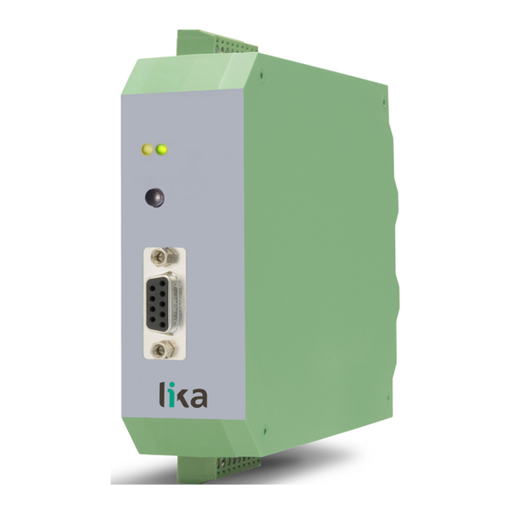
IF31
• Signal converter (1Vpp Sine/Cosine to incremental)
• Signal interpolator (multiplier / divider)
• Line Driver RS-422 / Push-Pull HTL outputs (AB0 /AB0)
• Input frequency up to 400 kHz / Output frequency up to 4 MHz
• Slim and space-saving housing for DIN rail mounting
Suitable for the following models:
IF31
•
Lika Electronic
User's guide
•
Tel. +39 0445 806600
General Contents
Preliminary information
1 - Safety summary
2 - Identification
3 - Mounting instructions
4 - Electrical connections
5 – Setting the DIL switches
6 - Miscellaneous hints
•
info@lika.biz
5
8
10
11
13
21
27
•
www.lika.biz
Advertisement
Table of Contents

Related Manuals for Lika IF31


Summary of Contents for Lika IF31
- Page 1 User's guide Smart encoders & actuators IF31 • Signal converter (1Vpp Sine/Cosine to incremental) • Signal interpolator (multiplier / divider) • Line Driver RS-422 / Push-Pull HTL outputs (AB0 /AB0) • Input frequency up to 400 kHz / Output frequency up to 4 MHz •...
- Page 2 Tous droits réservés. This document and information contained herein are the property of Lika Electronic s.r.l. and shall not be reproduced in whole or in part without prior written approval of Lika Electronic s.r.l. Translation, reproduction and total or partial modification (photostat copies, film and microfilm included and any other means) are forbidden without written authorisation of Lika Electronic s.r.l.
-
Page 3: Table Of Contents
General contents General contents..............................3 Typographic and iconographic conventions....................4 Preliminary information............................ 5 Compatibility....................................7 1 - Safety summary............................8 1.1 Safety......................................8 1.2 Electrical safety..................................8 1.3 Mechanical safety..................................8 2 - Identification.............................. 10 3 - Mounting instructions..........................11 3.1 Overall dimensions................................11 3.2 Installation notes.................................11 3.3 Cleaning, maintenance and service notes........................12 4 - Electrical connections.......................... -
Page 4: Typographic And Iconographic Conventions
Typographic and iconographic conventions In this guide, to make it easier to understand and read the text the following typographic and iconographic conventions are used: parameters and objects both of the device and the interface are coloured in GREEN; • alarms are coloured in RED;... -
Page 5: Preliminary Information
This guide is designed to provide the most complete information the operator needs to correctly and safely install and operate the IF31 converter and interpolator for 1Vpp Sine/Cosine encoders. IF31 is an encoder interface designed to convert the signals provided by 1Vpp Sine/Cosine encoders into incremental quadrature signals (AB0 /AB0 digital signals). - Page 6 All settings are made by means of two 12 pin DIL switches that are mounted on the top and on the bottom of the housing respectively. WARNING The power supply must be switched off before setting the DIL switches. Changes in the DIL switch positions will become active only after the unit is switched OFF and then ON again.
-
Page 7: Compatibility
Via external bridge Single track SINE/COSINE Currently not supported Supported signals (SIN / COS / REF) Specific features of the IF31 converter are: automatic generation of one Z pulse (REF) per each input period (selectable) • separate Z divider •... -
Page 8: Safety Summary
• failure to comply with these precautions or with specific warnings elsewhere in this manual violates safety standards of design, manufacture, and intended use of the equipment; • Lika Electronic assumes no liability for the customer's failure to comply with these requirements. 1.2 Electrical safety •... - Page 9 IF31 • do not subject the device to knocks or shocks; • respect the environmental characteristics of the device. MAN IF31 E 1.0.odt 1 - Safety summary 9 of 28...
-
Page 10: Identification
Information is listed in the delivery document too. Please always quote the order code and the serial number when reaching Lika Electronic for purchasing spare parts or needing assistance. For any information on the technical characteristics of the product, refer to the technical catalogue. -
Page 11: Mounting Instructions
Never tool the device. 3.1 Overall dimensions IF31 converter must be installed and protected inside the electric cabinet. It provides 35 mm top hat DIN rail mounting and can quickly snap onto a DIN rail with built-in DIN rail clips that require no additional brackets or supports. -
Page 12: Cleaning, Maintenance And Service Notes
(if necessary). Unauthorized opening and repair can have negative effects or failures to the measures of protection of the unit. MAN IF31 E 1.0.odt 3 - Mounting instructions 12 of 28... -
Page 13: Electrical Connections
X2 terminal blocks are available as shown in the drawing below. Terminal blocks have screw terminal connectors. Terminal block screws must be tightened using a slotted screwdriver having a 2 mm wide blade. MAN IF31 E 1.0.odt 4 - Electrical connections 13 of 28... -
Page 14: Power Supply To The Converter (X1 Terminal Block)
Encoder supply 1: +5.2 Vdc Encoder supply 2: Input voltage (V ) minus approx. 2 V Output current: max. 150 mA each Connections: X3 D-Sub 9 pin female connector MAN IF31 E 1.0.odt 4 - Electrical connections 14 of 28... -
Page 15: D-Sub 9-Pin Female Connector (X3 Connector) - Input Signals
SIN+, SIN-, COS+, COS-, REF+, and REF-. When long cables must be used, terminating resistors between the non-inverted and the inverted signal of each channel may be useful. MAN IF31 E 1.0.odt 4 - Electrical connections 15 of 28... - Page 16 The length of the cable should not exceed 5 metres. WARNING All inputs and outputs as well as the power supply refer to the same reference potential (GND)! MAN IF31 E 1.0.odt 4 - Electrical connections 16 of 28...
-
Page 17: Htl/Rs-422 Pulse Outputs (X2 Terminal Block) - Output Signals
“5.3 S1 and S2 DIL switches: frequency dividers” section on page 25. WARNING All inputs and outputs as well as the power supply refer to the same reference potential (GND)! MAN IF31 E 1.0.odt 4 - Electrical connections 17 of 28... -
Page 18: Control Inputs (X1 Terminal Block)
If the input frequencies are too high, the reset of the error may fail. The following errors are detected and signalled by the Error output signal as well as by the yellow LED. MAN IF31 E 1.0.odt 4 - Electrical connections 18 of 28... -
Page 19: S3 Error Release Push-Button
It warns about errors. For complete information refer to Yellow the “4.6 Control output (X1 terminal block) – Error out” section on page 18 No error is active ON (lit yellow) An error is active MAN IF31 E 1.0.odt 4 - Electrical connections 19 of 28... -
Page 20: Emc Guidelines
The device should be installed in a metal housing and as far away as possible from sources of interference. Run signal and control cables apart from power lines and other cables that emit electromagnetic noise. 4.10 Functional diagram MAN IF31 E 1.0.odt 4 - Electrical connections 20 of 28... -
Page 21: Setting The Dil Switches
The S2 DIL switch allows the activation of a programmable A/B divider and the selection of the test modes. WARNING Changes in the DIL switch positions will become active only after the unit is switched OFF and then ON again. MAN IF31 E 1.0.odt 5 – Setting the DIL switches 21 of 28... -
Page 22: Generic Settings Of Both S1 And S2 Dil Switches
6 and 7 of the X3 D- Sub connector are used Error is not static and is always deleted S2.09 Error is static and saved MAN IF31 E 1.0.odt 5 – Setting the DIL switches 22 of 28... -
Page 23: S1 Dil Switch: Interpolation And Filtering
However, when the glitch filter is switched ON, fast changes of speed can result in temporary proportional errors between the input frequency and the output frequency during acceleration. See the table in the following page. MAN IF31 E 1.0.odt 5 – Setting the DIL switches 23 of 28... - Page 24 156.25 kHz 3.90625 kHz 25 ns 4 MHz 80 kHz 100 ns 2.5 MHz 50 kHz 400 ns 625 kHz 12.5 kHz 1600 ns 156.25 kHz 3.125 kHz MAN IF31 E 1.0.odt 5 – Setting the DIL switches 24 of 28...
-
Page 25: S1 And S2 Dil Switches: Frequency Dividers
1 : 9 OFF OFF 1 : 10 1 : 11 1 : 12 OFF OFF 1 : 13 1 : 14 1 : 15 1 : 16 MAN IF31 E 1.0.odt 5 – Setting the DIL switches 25 of 28... -
Page 26: Dil Switches Setting Example
The delay time is constant and causes a frequency dependent phase shift between the input and the output signals. MAN IF31 E 1.0.odt 5 – Setting the DIL switches 26 of 28... -
Page 27: Miscellaneous Hints
IF31 converter does not provide potential separation, i.e. the GND of the unit is also the GND of the sensor at the same time. Therefore, it is important to ensure safe conditions of the earthing installation and to prevent earth loops and balance currents flowing through the unit. - Page 28 Document release Release date Description 17.06.2024 First issue Lika Electronic Via S. Lorenzo, 25 • 36010 Carrè (VI) • Italy Tel. +39 0445 806600 Fax +39 0445 806699 info@lika.biz • www.lika.biz...
Need help?
Do you have a question about the IF31 and is the answer not in the manual?
Questions and answers