Table of Contents
Advertisement
Quick Links
Smart encoders & actuators
LD300
LD301
LD302
LD303
LD305
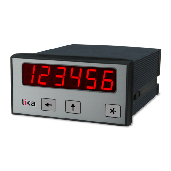
• Multifunction display for incremental encoders
• Position display, tachometer, start/stop speed display,...
• Digital, analogue, serial and relay outputs
• Multivoltage supply 24Vdc, 24/42Vac, 115/230Vac
Suitable for the following models:
LD300 display
•
LD301 display with analogue output
•
LD302 display with two presets and
•
transistor outputs
LD303 display with serial interface
•
LD305 display with two presets, relay
•
outputs and serial interface
Lika Electronic
User's guide
•
Tel. +39 0445 806600
•
info@lika.biz
9
10
12
13
18
22
24
40
44
•
www.lika.biz
Advertisement
Table of Contents

Related Manuals for Lika LD300


Summary of Contents for Lika LD300
-
Page 1: Table Of Contents
• Position display, tachometer, start/stop speed display,... • Digital, analogue, serial and relay outputs • Multivoltage supply 24Vdc, 24/42Vac, 115/230Vac Suitable for the following models: General Contents Preliminary information LD300 display • Safety summary LD301 display with analogue output • Mounting instructions LD302 display with two presets and •... - Page 2 Tous droits réservés. This document and information contained herein are the property of Lika Electronic s.r.l. and shall not be reproduced in whole or in part without prior written approval of Lika Electronic s.r.l. Translation, reproduction and total or partial modification (photostat copies, film and microfilm included and any other means) are forbidden without written authorisation of Lika Electronic s.r.l.
-
Page 3: General Contents
General contents General contents..............................3 Subject index............................... 7 Typographic and iconographic conventions....................8 Preliminary information............................ 9 1 Safety summary............................10 1.1 Safety......................................10 1.2 Electrical safety..................................10 1.3 Mechanical safety................................10 2 Identification..............................11 3 Mounting instructions..........................12 4 Electrical connections..........................13 4.1 Power supply..................................14 4.2 Aux. - Page 4 All......................................25 P_frEE....................................25 LmodE....................................25 no......................................25 1-qUA....................................25 4-qUA....................................25 7.2 Operational parameters..............................26 7.2.1 RPM, operation as tachometer or frequency counter................26 FrEqu......................................26 diSPL.......................................26 dPoint.....................................26 WAit......................................26 FiltEr.......................................26 OFF......................................26 16......................................26 7.2.2 Time, display of baking or processing time (reciprocal speed)..............27 diSfor......................................27 SEC......................................27 min......................................27 mi-SE....................................27 min.00....................................27 FrEqu......................................27 diSPL.......................................27 WAit......................................27 FiLtEr......................................27...
- Page 5 A_bdir....................................29 A u b....................................29 A - b....................................29 A_b .1....................................29 A_b .2....................................29 A_b .4....................................29 FActor.....................................29 SEt......................................29 rESEt.......................................29 no......................................29 front....................................29 E_tErn....................................29 Fr u E....................................29 dPoint.....................................29 7.2.5 Speed from differential time between a Start and a Stop input............30 timE......................................30 diSPL.......................................30 dPoint.....................................30 WAit......................................30 7.2.6 Linearisation points..............................30 7.3 Model LD301: additional settings for the analogue output................31 A-ChAr....................................31 -10_10....................................31...
- Page 6 7.5 Models LD303 & LD305: additional settings for the serial interface............35 S-Unit....................................35 S-Form....................................35 7 E 1....................................35 7 E 2....................................35 7 0 1....................................35 7 0 2....................................35 7 no 1....................................35 7 no 2....................................35 8 E 1....................................35 8 0 1....................................35 8 no 1....................................35 8 no 2....................................35 S-bAUd....................................35 9600....................................35...
- Page 7 Subject index LmodE...................25 A-ChAr..................31 AnAbEG.................32 modE..................29 AnAEnd.................32 OFFSEt...................31 bASE..................28 briGht..................24 P01_X..................30 P01_Y..................30 CHAr..................24 P16_X..................30 CHAr 1...................33 P16_Y..................30 CHAr 2...................33 PrES_1...................34 CodE..................25 PrES_2...................34 diSfor..................27 rESEt...................28p. diSPL................26p., 30 dPoint.................26, 29p. S-bAUd.................35 S-CodE..................36 FActor..................29 S-Form..................35 FiltEr..................26 S-mod...................36 FiLtEr..................27 S-tim..................36 FrEqu..................26p. S-Unit..................35 SEt...................29 StArt..................28 GAin..................31 timE..................30 HYSt 1...................33...
-
Page 8: Typographic And Iconographic Conventions
Typographic and iconographic conventions In this guide, to make it easier to understand and read the text the following typographic and iconographic conventions are used: parameters and objects both of the device and the interface are coloured in GREEN; • alarms are coloured in RED;... -
Page 9: Preliminary Information
The user's interface is a multi-function keyboard fitted with 3 keys and a 7-segment and 6- digit LED display. In the series the following models are available: LD300 is a display only version; • LD301 provides an additional analogue output;... -
Page 10: Safety Summary
• failure to comply with these precautions or with specific warnings elsewhere in this manual violates safety standards of design, manufacture, and intended use of the equipment; • Lika Electronic assumes no liability for the customer's failure to comply with these requirements. 1.2 Electrical safety •... -
Page 11: Identification
Information is listed in the delivery document too. Please always quote the order code and the serial number when reaching Lika Electronic for purchasing spare parts or needing assistance. For any information on the technical characteristics of the product, refer to the technical catalogue. -
Page 12: Mounting Instructions
LD30x 3 Mounting instructions WARNING Mount the unit with power supply disconnected. Mount the display into the provided cut-out (approx. 91 x 44 mm, 3.583 x 1.732’’) without panel clips. Install panel clips on the display housing and screw until fixed. 110,0 (4.331’’) 96,0 (3.780’’) 91,0 (3.583) -
Page 13: Electrical Connections
LD30x 4 Electrical connections WARNING Turn OFF the power supply before connecting the device. LD300 Display unit only Special versions with TTL inputs (option -M8-) provide a +5V 9 10 auxiliary output on terminal 7, instead of +24V Only when you like... -
Page 14: Power Supply
LD30x LD305 Display unit with 2 presets, 2 relay outputs and a serial RS-232/RS- 485 interface Special versions with TTL inputs (option -M8-) provide a +5V auxiliary output on terminal 7, instead of +24V LD305 has -P4- option only, it needs 17Vdc - 30Vdc power supply * Contact positions are shown in... -
Page 15: Inputs A, B And Reset
LD30x 4.3 Inputs A, B and Reset In the basic set-up menu (see the “7.1 Basic settings” section on page 24) these inputs can be configured to PNP (switch to +) or to NPN (switch to -). This configuration is valid for all three inputs at a time. The factory setting is always PNP. -
Page 16: Optocoupler / Transistor Outputs (Ld302 Model Only)
LD30x the sign in the display. The outputs provide a 14-bit resolution and the response time at each change of the measuring value is approx. 7 msec. (f > 143 Hz). The maximum current of the voltage output is 2 mA and the load on the current output can vary between 0 and max. -
Page 17: Relay Outputs (Ld305 Model Only)
LD30x WARNING 1. Never set DIL switch positions 1 and 2 or DIL switch positions 3 and 4 to ON at the same time! 2. After setting the switch, shift the print carefully back to its housing, in order to avoid damaging the front pins for connection with the front plate. -
Page 18: Operating The Front Keys
LD30x 5 Operating the front keys For set-up and other operations the unit is fitted with three front keys which will be denominated as follows in the next pages: ENTER (Input) (Setting) (Command) The functions of the keys are depending on the current operating state of the unit. -
Page 19: Selection And Setting Of Parameters
LD30x 5.2 Selection and setting of parameters 5.2.1 Selecting a parameter The ENTER key will scroll through the menu. The SET key allows to select the corresponding item and change the setting or the numeric value. After this, the selection can be saved by pressing the ENTER key again, which automatically changes over to the next menu item. -
Page 20: Parameters List
LD30x 5.3 Teach operation NOTE The time-out function remains disabled during all Teach operations. Function ENTER key will terminate or abort any Teach operation in progress SET function is fully similar to normal set-up operation CMD key will save the display value in the register and change over to the next interpolation point For further details on the Teach procedure see the “8.2 Manual input or “teaching“... -
Page 21: Code Locking Of The Keypad
LD30x 5.5 Code locking of the keypad When the code locking of the keypad has been switched on (see on page 25), any key access first results as follows: ------ To access the menu you must press the following key sequence: within 10 seconds, otherwise the unit will automatically return to the normal display mode. -
Page 22: Operator Menu
The subsequent table shows the general structure of the menu. Detailed descriptions of all parameters will follow in the “7 - Set up procedure“ section on page 24. 6.1 Overview of basic parameters LD300 LD301 LD302 LD303 LD305... -
Page 23: Operational Parameters Overview
30 Frequency Display Format Base (Resolution) Counter Mode Time Display Value Frequency Start/Stop Scaling Factor Display Value LD300 Decimal Point Display Value Auto Reset Set Value Decimal Point Wait Time Wait Time Reset/Set Latch Function Wait Time Average Filter... -
Page 24: Set Up Procedure
7 Set up procedure For better understanding the following “7.1 Basic settings” and “7.2 Operational parameters” sections explain settings related to the display only model (LD300). Model-specific settings for analogue output model (LD301), Preselections models (LD302 and LD305) and Serial Link models (LD303 and LD305) will be explained separately under sections from “7.3 Model LD301: additional settings... -
Page 25: Code
LD30x Menu Setting range Default CodE Keypad protection code Keypad enabled continuously. Keypad locked for any access. Keypad locked, except for access to preselections 1 and 2 (LD302 & LD305 models only, see the “7.4 P_frEE Models LD302 & LD305: additional settings for preselections”... -
Page 26: Operational Parameters
LD30x 7.2 Operational parameters 7.2.1 RPM, operation as tachometer or frequency counter (Input A = frequency input, Input B not in use) Menu Setting Range Default Frequency 1 Hz to FrEqu 1000 Set a typical operating frequency for your 25 000 Hz application. -
Page 27: Time, Display Of Baking Or Processing Time (Reciprocal Speed)
LD30x 7.2.2 Time, display of baking or processing time (reciprocal speed) (Input A = frequency input, Input B not in use) Menu Setting Range OS* Default diSfor Display Format Select between seconds, minutes, minutes and seconds or minutes with two decimal positions. This will also automatically set your decimal point to the proper place. -
Page 28: Timer, Stopwatch
LD30x 7.2.3 Timer, Stopwatch Please note that open NPN inputs are always “HIGH“ and open PNP inputs are always “LOW“. Menu Setting Range OS* Default bASE SEC.000 Time base / Resolution of the timer SEC.000 Milliseconds SEC.00 1/100 of a second SEC.0 1/10 of a second Integer seconds... -
Page 29: Count, Counter Mode
LD30x 7.2.4 Count, Counter mode Menu Setting Range OS* Default modE A_b .1 Counting Mode Input A counts and input B selects the counting A_bdir direction (LOW = increment, HIGH = decrement). A u b Summing counter, A + B. A - b Differential counter, A –... -
Page 30: Speed From Differential Time Between A Start And A Stop Input
LD30x 7.2.5 Speed from differential time between a Start and a Stop input Input A operates as a start input and input B operates as a Stop input. The differential time between start and stop will be converted into the speed of the passing object. -
Page 31: Model Ld301: Additional Settings For The Analogue Output
LD30x 7.3 Model LD301: additional settings for the analogue output The Basic menu provides the following additional settings: Menu Setting Range OS** Default A-ChAr Analogue characteristics 0_10 Select one of the following options: -10_10 +/-10 V (bipolar) 0_10 0-10 V (positive output only) 4_20 4-20 mA current output. -
Page 32: Anabeg
LD30x The following Operational Parameters provide scaling of the analogue output: Menu Setting Range Default AnAbEG Analogue-Begin -199999 ... 999999 Start value of the analogue output. AnAEnd Analogue-End 10000 -199999 ... 999999 End value of the analogue output. By means of these two parameters any window of the whole display range can be mapped onto the analogue output. -
Page 33: Models Ld302 & Ld305: Additional Settings For Preselections
LD30x 7.4 Models LD302 & LD305: additional settings for preselections The basic set-up menu provides the following additional parameters: Menu Range OS**** Default CHAr 1 __r GE Switching characteristics of output 1 __r GE Greater/Equal: output to switch statically ”ON” when display value ≥ preset value. __r LE Lower/Equal: output to switch statically ”ON”... -
Page 34: Pres_1
LD30x The following operational parameters provide setting of the switching points: Menu Setting Range Default PrES_1 Preselection 1 -199999 ... 10000 999999 PrES_2 Preselection 2 -199999 ... 5000 999999 The working direction of the Hysteresis depends on the setting of the switching characteristics. -
Page 35: Models Ld303 & Ld305: Additional Settings For The Serial Interface
LD30x 7.5 Models LD303 & LD305: additional settings for the serial interface The basic set-up menu contains the main parameters for configuration of the serial interface. Menu Setting Range OS* Default S-Unit Serial Unit Number You can assign any address number between 11 and 99 to your unit. -
Page 36: S-Tim
LD30x The following operational parameters provide setting of the communication profile: Menu Setting Range OS* Default S-tim Serial Timer Setting 0.000 allows manual activation of a serial data 0.000; transmission at any time. All other settings specify the 0.010 … 0.1 sec cycle time for automatic transmission (provided the S- 9.999 sec... -
Page 37: Pc-Mode
LD30x 7.5.1 PC-Mode Communication in PC mode allows free readout of all parameters and registers of the unit. The example below shows the details of communication for serial readout of the current display value. This is the general format of a serial request string: EOT = Control character (Hex 04) AD1 = Unit address, High Byte... - Page 38 LD30x Units with serial link also allow setting or resetting the counter by serial command (similar to the external input or front key function). To activate the Reset command, please write “1” in register code “60”. To release the Reset command again, write “0”...
-
Page 39: Printer-Mode
LD30x 7.5.2 Printer-Mode The Printer mode allows cyclic or manual activation of transmissions of the specified register data. The corresponding register can be specified by means of parameter S-CodE. Another parameter called S-mod allows the selection between two different string types: “S-mod“... -
Page 40: Special Functions
LD30x 8 Special functions 8.1 Linearisation This function allows a non-linear input signal to be converted into a linear representation or vice versa. 16 interpolation points are available, they can be freely arranged over the whole measuring range at any distance. Between two points the unit will interpolate automatically straight lines. - Page 41 LD30x EXAMPLE The picture below shows a sluiceway where the gate is controlled by means of an incremental encoder. We would like to display the clearance of the gate "d", the existing encoder information is proportional to the angular information φ. Display value φ...
-
Page 42: Manual Input Or "Teaching" Of The Interpolation Points
LD30x 8.2 Manual input or “teaching“ of the interpolation points Interpolation points to form the linearisation curve can be entered one after each other, using the same procedure as for all other numeric parameters. This means you will have to enter all parameters P01_x to P16_x and P01_y to P16_y manually using the keypad. - Page 43 LD30x Once we have reached and stored the last interpolation points • P16_x/y, the routine will restart with P01_x again. You are free to double-check your settings once more or to make corrections. To finish the Teach procedure, keep ENTER key down for about 2 •...
-
Page 44: Parameters List
LD30x 9 Parameters list 9.1 General Min. Max. Default Serial Description Text Positions Characters value value value code See the “7.1 Basic settings” section on page 24 Unit Type tYPE Characteristic CHAr briGht Brightness CodE Code See the “7.2.1 RPM, operation as tachometer or frequency counter” section on page 26 Frequency (Hz) FrEqu 25000... -
Page 45: Linearisation
LD30x 9.2 Linearisation See the “7.2.6 Linearisation points” section on page 30 Min. Max. Default Serial Description Text Positions Characters value value value code L_Mode LmodE P1(x) P01_H -199999 999999 999999 P01_ P1(y) -199999 999999 999999 P02_H -199999 999999 P2(x) 999999 P02_ P2(y) -
Page 46: Analogue Output (Model Ld301)
LD30x 9.3 Analogue output (model LD301) See the “7.3 Model LD301: additional settings for the analogue output” section on page 31 Min. Max. Default Serial Description Text Positions Characters value value value code Analogue Start AnAbEG -199999 999999 Analogue End AnAEnd -199999 999999 10000... - Page 47 This page intentionally left blank...
- Page 48 “WAit“ & “LmodE” parameters description updated, “Loo_Hi” parameter added, “4.4 03.08.2015 Adjustable analogue output (LD301 model only)” section updated, OS range numbers added, revised edition 08.08.2017 General review, LD305 model added Lika Electronic Via S. Lorenzo, 25 • 36010 Carrè (VI) • Italy Tel.
Need help?
Do you have a question about the LD300 and is the answer not in the manual?
Questions and answers