Table of Contents
Advertisement
Quick Links
IF50
User's manual
IF50
Description
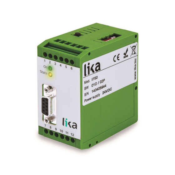
IF50 is the small, low-cost yet high-performing converter for industrial
applications suitable for use in installations where incremental counting of
positions or events must be converted to either analogue format or serial data.
The unit has been designed as a compact module with 12 screw terminals and a
9-position SUB-D connector (female). The housing is suitable for standard DIN
rail mounting.
Table of contents
MAN IF50 I_E 1.0.odt
41 / 80
Advertisement
Table of Contents

Related Manuals for Lika IF50


Summary of Contents for Lika IF50
-
Page 1: Table Of Contents
User's manual IF50 Description IF50 is the small, low-cost yet high-performing converter for industrial applications suitable for use in installations where incremental counting of positions or events must be converted to either analogue format or serial data. The unit has been designed as a compact module with 12 screw terminals and a 9-position SUB-D connector (female). -
Page 2: Safety Summary
• elsewhere in this manual violates safety standards of design, manufacture, and intended use of the equipment; Lika Electronic s.r.l. assumes no liability for the customer's failure to • comply with these requirements. 1.2 Electrical safety Turn OFF power supply before connecting the device;... -
Page 3: Identification
Information is listed in the delivery document too. Please always quote the ordering code and the serial number when reaching Lika Electronic s.r.l. for purchasing spare parts or needing assistance. For any information on the technical characteristics of the product, refer to the technical catalogue. - Page 4 In general, HTL encoders will be supplied from the same source as the converter. The unit provides an auxiliary 5.5 volts output (stabilized, max. 250 mA) to supply TTL encoders. MAN IF50 I_E 1.0.odt 3 - Introduction 44 / 80...
-
Page 5: Mounting Instructions
WARNING Mount the unit with power supply disconnected. IF50 converter must be installed and protected inside the electric panel. It provides DIN rail mounting and can quickly snap onto a DIN rail with built-in DIN rail clips that require no additional brackets or supports. -
Page 6: Electrical Connections
70 mA (see the datasheet). 5.1 Incremental encoders TTL / RS-422 If applicable, the encoder can be supplied by the IF50 converter. If the encoder is already supplied by a remote source, we recommend fully differential operation, with no GND connection between encoder and converter (see Figure below). - Page 7 2 mA, the current output accepts loads between 0 and 270 . The analogue ground uses a separate terminal, which however is internally connected to the GND potential of the power supply. MAN IF50 I_E 1.0.odt 5 - Electrical connections 47 / 80...
- Page 8 The unit provides a RS-232 interface and a RS-485 interface, however only one can be used at a time. Serial communication allows to read out the counting result and to set parameters and variables via PC, according to need. MAN IF50 I_E 1.0.odt 5 - Electrical connections 48 / 80...
-
Page 9: Dil Switch Settings
Set value B Position 4 ON: Power-down memory ON. Upon power up the counter re-loads the value stored previously before power down. Power Up Mode. 2 See parameter MAN IF50 I_E 1.0.odt 6 - DIL switch settings 49 / 80... - Page 10 Symmetric TTL signals or RS-422 signals (A, Standard TTL encoders 0 0 0 0 /A), (B, /B) (differential, including inverted providing A, /A, B, /B signal) output channels MAN IF50 I_E 1.0.odt 6 - DIL switch settings 50 / 80...
- Page 11 “1”, the format will be “0 … +10 1 0 Current 4 – 20 mA V” output under default conditions. 1 1 Current 0 – 20 mA MAN IF50 I_E 1.0.odt 6 - DIL switch settings 51 / 80...
- Page 12 After successful commissioning, please make sure positions 6 and 8 are both set to “ON”. Otherwise, each power supply or even just unintentional touch of the button will cause your parameter settings to be overwritten! MAN IF50 I_E 1.0.odt 6 - DIL switch settings 52 / 80...
-
Page 13: Set Up Procedure
LED will switch off. After you complete the TEACH procedure, your analogue output is set to 0–10 volts swing between the minimum and the maximum counter state. MAN IF50 I_E 1.0.odt 7 – Set up procedure 53 / 80... - Page 14 (with direction signal)”, yet the minimum and maximum counter states already refer to the sum or the difference of the count A/B Mode on both inputs (see parameter on page 59). MAN IF50 I_E 1.0.odt 7 – Set up procedure 54 / 80...
-
Page 15: Actual Counter State Readout Via Serial Port
Actual output voltage of the analogue output, scaling 0 – 10 000 mV *) Under consideration of the scaling operands as shown in the section “11.1 Register < :8 > settings“ on page 58. MAN IF50 I_E 1.0.odt 8 - Actual counter state readout via serial port 55 / 80... -
Page 16: Pc Set-Up Using The Os3.2 Operator Software
If the serial settings of the unit should be unknown, you can run the • SCAN function from the TOOLS menu to find out them. MAN IF50 I_E 1.0.odt 9 - PC set-up using the OS3.2 operator software 56 / 80... -
Page 17: Main Window And Soft Keys
The colour bar graph in the bottom centre displays the actual output state in the range -/+100 % of full scale. Keys in the CONTROL pane are are designed to activate readout, transmission and storage of parameters. MAN IF50 I_E 1.0.odt 10 – Main window and soft keys 57 / 80... -
Page 18: Parameter Settings
0 the whole conversion will be skipped, resulting in lower calculation time and the shortest possible conversion time. Multiplier Divisor The calculation resulting from [ ] must not exceed 15 000! MAN IF50 I_E 1.0.odt 11 - Parameter settings 58 / 80... - Page 19 (x1) or full quadrature count (x4), by accepting either rising edges from input A only, or all rising and falling edges from inputs A and B. simple count (x1) quadrature count (x4) MAN IF50 I_E 1.0.odt 11 - Parameter settings 59 / 80...
- Page 20 2 = unit sets the counter to the value set in the registers Set value A value B, see the register Set value A Input on page 61 and the register function on page 66. MAN IF50 I_E 1.0.odt 11 - Parameter settings 60 / 80...
- Page 21 000). The analogue output complies with the new counter state according to Input function the set output scaling. See the register on page 66. Multiplier A Multiplier for multiple count of one input impulse on input A (001 – 999). MAN IF50 I_E 1.0.odt 11 - Parameter settings 61 / 80...
- Page 22 000). The analogue output complies with the new counter state according to Input function the set output scaling. See the register on page 66. Multiplier B Multiplier for multiple count of one input impulse on input B (001 – 999). MAN IF50 I_E 1.0.odt 11 - Parameter settings 62 / 80...
- Page 23 (either -9999 mV ... 0 ... +9999 mV or -19998 µA ... 0 ... +19998 µA). Analogue Gain This register sets the maximum output swing of the analogue output. Setting 1000 will result in an output swing of either 10 volts or 20 milliamps. MAN IF50 I_E 1.0.odt 11 - Parameter settings 63 / 80...
- Page 24 Setting Baud 0 (factory default) 9600 4800 2400 1200 19200 38400 Serial Format Setting Data bits Parity Stop bits 0 (factory default) even even none none even none none MAN IF50 I_E 1.0.odt 11 - Parameter settings 64 / 80...
- Page 25 Details about this protocol can be found in the file Serial Protocol x.pdf which is available for download from Lika Electronic website. When Printer Mode is enabled, the unit sends data without any request and...
- Page 26 Set value B it inhibits the counter A (count disabled) it inhibits the counter B (count disabled) it inhibits both counters A and B it activates a serial data transmission cycle MAN IF50 I_E 1.0.odt 11 - Parameter settings 66 / 80...
- Page 27 Since the counters use impulse scaling factors, there may be remainders which need to be considered later in order to go on with error-free counting. These Backup Rest A Backup Rest B remainders are stored in the corresponding registers. MAN IF50 I_E 1.0.odt 11 - Parameter settings 67 / 80...
- Page 28 P1(y) … P16(y) Registers to set the substitute values of the interpolation points for linearisation. Further information are available in the section “12.2 Free programmable linearisation“ on page 69. MAN IF50 I_E 1.0.odt 11 - Parameter settings 68 / 80...
-
Page 29: Scaling And Linearisation Functions
P1(x) With register • P16(x) to –100% and register to +100% . This enables the user to set curves which are not symmetric to the zero position. MAN IF50 I_E 1.0.odt 12 – Scaling and linearisation functions 69 / 80... - Page 30 When you use the OSCILLOSCOPE function of the operator software, you must set the serial code < :1 > to record the analogue output. MAN IF50 I_E 1.0.odt 12 – Scaling and linearisation functions 70 / 80...
-
Page 31: Monitor Function
DEFINITIONS window. You will find a list of all accessible parameters and actual values; however some items are not available to user. Using IF50 converter, the following registers may be useful: C2 Description Actual conversion result in percentage of the „full scale“, format xxx.xxx % *) - Page 32 STORE TO FILE button first and then set the corresponding check box. After starting the monitor you will see the following window, where all values are updated continuously. MAN IF50 I_E 1.0.odt 13 - Monitor function 72 / 80...
-
Page 33: Data Readout Via Serial Interface
14 – Data readout via serial interface All register codes described in the previous section “13 - Monitor function” are also available for serial readout via PC or PLC. IF50 converter uses the DRIVECOM communication standard according to ISO 1745. Details about this protocol can be found in the file Serial Protocol x.pdf which is available for... -
Page 34: Testing Functions
When you select the TEST command in the TOOLS menu, you are able to verify the following data, by clicking on the corresponding field: actual counter values; • DIL switch settings; • internal supply voltages; • analogue output state. • MAN IF50 I_E 1.0.odt 15 - Testing functions 74 / 80... -
Page 35: Parameters List
100000 +/- 6 P1(y) P2(x) -100000 100000 100000 +/- 6 P2(y) -100000 100000 100000 +/- 6 A3…(A9)…(C9) P16(x) -100000 100000 100000 +/- 6 P16(y) -100000 100000 100000 +/- 6 MAN IF50 I_E 1.0.odt 16 - Parameters list 75 / 80... - Page 36 This page intentionally left blank...
- Page 37 This page intentionally left blank...
- Page 38 This page intentionally left blank...
- Page 39 This page intentionally left blank...
- Page 40 Document release Description 1st issue Lika Electronic Via S. Lorenzo, 25 - 36010 Carrè (VI) - Italy Tel. +39 0445 806600 Fax +39 0445 806699 Italy: eMail info@lika.it - www.lika.it World: eMail info@lika.biz - www.lika.biz...
Need help?
Do you have a question about the IF50 and is the answer not in the manual?
Questions and answers