Table of Contents
Advertisement
Quick Links
Smart encoders & actuators
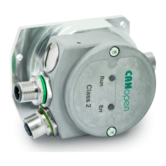
IF55 ROT CB
• SSI to CANopen converter
• Suitable for SSI rotary encoders
• Accepts MSB & LSB Aligned protocols up to 30 bits
• Cable and M12 connector outputs
• CANopen in compliance with DS 301 and DS 406 profiles
Suitable for the following models:
IF55 ROT CB
•
IF55 ROT CB-C
•
Lika Electronic
User's guide
•
Tel. +39 0445 806600
DS406 encoder profile
General Contents
1 - Safety summary
2 - Identification
3 - Mounting instructions
4 - Electrical connections
5 - Getting started
6 - CANopen® interface (DS 406)
7 - Setting-up
8 - Default parameters list
•
info@lika.biz
19
21
22
25
34
40
81
85
•
www.lika.biz
Advertisement
Table of Contents

Related Manuals for Lika IF55 ROT CB


Summary of Contents for Lika IF55 ROT CB
-
Page 1: User's Guide
User's guide Smart encoders & actuators IF55 ROT CB DS406 encoder profile • SSI to CANopen converter • Suitable for SSI rotary encoders • Accepts MSB & LSB Aligned protocols up to 30 bits • Cable and M12 connector outputs •... - Page 2 Tous droits réservés. This document and information contained herein are the property of Lika Electronic s.r.l. and shall not be reproduced in whole or in part without prior written approval of Lika Electronic s.r.l. Translation, reproduction and total or partial modification (photostat copies, film and microfilm included and any other means) are forbidden without written authorisation of Lika Electronic s.r.l.
-
Page 3: Table Of Contents
General contents User's guide......................................1 General contents.....................................3 Subject index.....................................6 Typographic and iconographic conventions........................7 Preliminary information................................8 Glossary of CANopen terms..............................9 1 - Safety summary..................................19 1.1 Safety......................................19 1.2 Electrical safety..................................19 1.3 Mechanical safety................................20 2 - Identification..................................21 3 - Mounting instructions..............................22 3.1 Overall dimensions................................22 3.2 Installation on panel (Figure 2).............................23 3.3 Installation with DIN rail clip (Figure 3)........................23 4 - Electrical connections...............................25... - Page 4 6.8.1 Communication Profile Area objects (DS 301)....................47 1000-00 Device type..............................47 1001-00 Error register..............................47 1003 Pre-defined error field...........................47 1005-00 COB_ID SYNC message..........................48 1008-00 Manufacturer device name.........................48 1009-00 Manufacturer hardware version......................48 100A-00 Manufacturer software version.......................48 100C-00 Guard time..............................48 100D-00 Life time factor............................48 1010-01 Store parameters............................49 1011-01 Restore default...
- Page 5 Current operating state............................71 6501-00 Singleturn resolution..........................72 6502-00 Number of distinguishable revolutions..................72 6504-00 Supported alarms............................73 6506-00 Supported warnings..........................73 6507-00 Profile and software version......................74 6508-00 Operating time............................74 6509-00 Offset value..............................74 650A-01 Module identification..........................74 650B-00 Serial number..............................74 6.9 SDO abort codes..................................76 6.10 Emergency (EMCY) objects............................77 6.11 Node guarding protocol..............................78 7 - Setting-up....................................81 7.1 Setting the Operational, Pre-operational state......................81...
-
Page 6: Subject Index
Subject index 6502-00 Number of distinguishable revolutions .....................72 1000-00 Device type............47 6504-00 Supported alarms.........73 1001-00 Error register...........47 6506-00 Supported warnings........73 1003 Pre-defined error field........47 6507-00 Profile and software version....74 1005-00 COB_ID SYNC message.......48 6508-00 Operating time..........74 1008-00 Manufacturer device name......48 6509-00 Offset value.............74 1009-00 Manufacturer hardware version....48 650A-01 Module identification.........74... -
Page 7: Typographic And Iconographic Conventions
Typographic and iconographic conventions In this guide, to make it easier to understand and read the text the following typographic and iconographic conventions are used: parameters and objects both of the device and the interface are coloured in GREEN; • alarms are coloured in RED;... -
Page 8: Preliminary Information
The present manual is specifically designed to describe the SSI to CANopen IF55 model for rotary encoders (order code IF55 ROT CB). For information on the SSI to CANopen IF55 model for linear encoders (order code IF55 LIN CB) refer to the specific documentation. -
Page 9: Glossary Of Canopen Terms
Glossary of CANopen terms CANopen, like many other networking systems, has a set of unique terminology. Table below contains a few of the technical terms used in this guide to describe the CANopen interface. They are listed in alphabetical order. The Glossary is owned and copyrighted by the CAN in Automation international users' and manufacturers' group. - Page 10 device recovers from bus off state, it has to transmit the boot- up message and it is recommended to send an Emergency message with the appropriate error code. Controller Area Network (CAN) is a serial bus system originally developed by the Robert Bosch GmbH. It is internationally standardized by ISO 11898-1.
- Page 11 loop controllers supports also multi-channel devices. CiA DS 406 The CANopen device profile for encoders defines the communication of rotating as well as linear sensors. The draft standard proposal for programmable CANopen CiA DSP 302 devices includes CANopen manager functions, dynamic SDO connections, standardized boot-up procedure for NMT Slaves as well as program download.
- Page 12 the interface for feeder sub-systems. CiA DSP 415 The CANopen application profile for asphalt pavers specifies interfaces to different devices used in road construction machinery. CiA DSP 416 The CANopen application profile for building doors specifies interfaces for locks, sensors, and other devices used in electronically controlled building doors.
- Page 13 Conformance test plan Definitions of test cases that have to be passed successfully in order to achieve conformance to a communication standard. The conformance test plan for CAN is standardized by ISO 16845. Conformance test tool A conformance test tool is the implementation of a conformance test plan.
- Page 14 Error control message The CANopen error control messages are mapped to a single 1-byte CAN data frame assigned with a fixed identifier that is derived from the device's Node ID. It is transmitted as boot-up Pre-operational message before entering state after initialization, and it is transmitted if remotely requested by the NMT Master (node guarding) or periodically by the device (heart-beat).
- Page 15 Index 16-bit address to access the CANopen dictionary; for array and records the address is extended by an 8-bit Subindex. Inhibit timer Object in CANopen for PDOs and Emergency messages that forbids for the specified time (inhibit time) a transmission of this communication object.
- Page 16 NMT state machine The NMT state machines support different states and the highest prior CAN message transmitted controls the transition to the states by the NMT Master. Node guarding Mechanism used in CANopen and CAL to detect bus off or disconnected devices.
- Page 17 the corresponding data frame identified by the very same identifier. The remote frame's DLC has the value of the corresponding data frame DLC. The data field of the remote frame has a length of 0 byte. Remote transmission Bit in the arbitration field indicating if the frame is a remote frame (recessive value) or a data frame (dominant value).
- Page 18 sample the inputs mapped into synchronous TPDOs. Receiving this message causes the node to set the outputs to values received in the previous synchronous RPDO. Termination resistor In CAN high-speed networks with bus topology, both ends are terminated with resistors in order to suppress reflections. TIME message Standardized message in CANopen containing the time as a 6- byte value given as ms after midnight and days after 1st...
-
Page 19: Safety Summary
failure to comply with these precautions or with specific warnings elsewhere in this manual violates safety standards of design, manufacture, and intended use of the equipment; Lika Electronic assumes no liability for the customer's failure to comply with these requirements. 1.2 Electrical safety ... -
Page 20: Mechanical Safety
delicate electronic equipment: handle with care; do not subject the device and the shaft to knocks or shocks; respect the environmental characteristics declared by manufacturer. MAN IF55 ROT CB E 1.2.odt 1 - Safety summary 20 of 88... -
Page 21: Identification
Information is listed in the delivery document too. Please always quote the order code and the serial number when reaching Lika Electronic for purchasing spare parts or needing assistance. For any information on the technical characteristics of the product refer to the technical catalogue. -
Page 22: Mounting Instructions
Installation and maintenance operations have to be carried out by qualified personnel only, with power supply disconnected and mechanical parts compulsorily in stop. 3.1 Overall dimensions (values are expressed in mm) Figure 1 MAN IF55 ROT CB E 1.2.odt 3 - Mounting instructions 22 of 88... -
Page 23: Installation On Panel (Figure 2)
2. Delicate electronic circuits and wirings are located inside the cap 5. Thus this operation has to be accomplished by skilled personnel only. Please pay careful attention and observe great precaution when carrying out this operation. MAN IF55 ROT CB E 1.2.odt 3 - Mounting instructions 23 of 88... - Page 24 M4 x 8 screw 4; it has to be screwed on the inner side of the flange 2; replace the cap 5 and fix it by means of the screws 6. • MAN IF55 ROT CB E 1.2.odt 3 - Mounting instructions 24 of 88...
-
Page 25: Electrical Connections
Be careful not to damage the internal components when you perform this operation. To remove the connection cap loosen the two screws 1 (Figure 5). Please be careful with the internal connector. MAN IF55 ROT CB E 1.2.odt 4 - Electrical connections 25 of 88... -
Page 26: Ssi Connection (Figure 4)
* The power supply voltage level must be set through the POWER SUPPLY DIP switch located inside the enclosure of the converter, see the “4.7 POWER SUPPLY DIP switch (Figure 8)” section on page 29. MAN IF55 ROT CB E 1.2.odt 4 - Electrical connections 26 of 88... -
Page 27: Canopen Converter With Pgs: Cb Version (Figure 4 And Figure 6)
CAN Shield CAN GND is the 0V reference of CAN signals, it is not connected to 0Vdc supply voltage. Connect the cable shield to the cable gland. MAN IF55 ROT CB E 1.2.odt 4 - Electrical connections 27 of 88... -
Page 28: Canopen Converter With M12 Connectors: Cb-C Version (Figure 4 And Figure 7)
We suggest using the ground point provided in the connection cap (see the Figure 4, use one TCEI M3 x 6 cylindrical head screw with two tooth lock washers). MAN IF55 ROT CB E 1.2.odt 4 - Electrical connections 28 of 88... -
Page 29: Shield Connection
(default setting); set the POWER SUPPLY DIP switch to DOWN position to provide +5Vdc ±5% power supply voltage level to the encoder. MAN IF55 ROT CB E 1.2.odt 4 - Electrical connections 29 of 88... -
Page 30: Baud Rate: Dip A (Figure 6 And Figure 7)
DIP A: Switch off the device and set the binary value of the transmission rate considering that: ON = 1, OFF = 0. 1 LSB 3 MSB MAN IF55 ROT CB E 1.2.odt 4 - Electrical connections 30 of 88... -
Page 31: Node Number: Dip B (Figure 6 And Figure 7)
The node number must be set via hardware by using the DIP B dip switch. Allowed node addresses range between 1 and 127. The default value is 1. DIP B: MAN IF55 ROT CB E 1.2.odt 4 - Electrical connections 31 of 88... -
Page 32: Rt Bus Termination (Figure 6 And Figure 7)
Deactivated: if the device is neither the first nor 1 = 2 = OFF the last device in the transmission line MAN IF55 ROT CB E 1.2.odt 4 - Electrical connections 32 of 88... -
Page 33: Diagnostic Leds (Figure 4)
Generic error or Blinking page 77 ff No error During initialization, the device carries out a hardware test to check LEDs operation. Both LEDs light up. MAN IF55 ROT CB E 1.2.odt 4 - Electrical connections 33 of 88... -
Page 34: Getting Started
= 1; see on page 62) and then set the resolution you need for 6001-00 Programmable pulse per your application next to the revolution 6002-00 Programmable total measuring range objects (see on page 63); MAN IF55 ROT CB E 1.2.odt 5 - Getting started 34 of 88... - Page 35 6502-00 Number of distinguishable revolutions objects are automatically set accordingly and used to arrange the position information Total Physical Resolution = 6501-00 Singleturn resolution 6502-00 Number of distinguishable revolutions MAN IF55 ROT CB E 1.2.odt 5 - Getting started 35 of 88...
- Page 36 6000-00 Operating parameters object 6001-00 Now set the resolution you need for your application next to the Programmable pulse per revolution 6002-00 Programmable total measuring range objects MAN IF55 ROT CB E 1.2.odt 5 - Getting started 36 of 88...
- Page 37 Multiturn Resolution: 14 bits = 16,384 rev. (“16384”, see the order code in the product datasheet). Output code: Gray code (“GA”, see the order code in the product datasheet). SSI protocol: 32-bit “LSB Right Aligned” protocol (see the User's manual). MAN IF55 ROT CB E 1.2.odt 5 - Getting started 37 of 88...
-
Page 38: Quick Reference
read the current position (in a cyclic mode and/or in a synchronous mode). The default Baud rate and Node-ID are: Baud rate = 500 Kbit/s Node-ID = 1 MAN IF55 ROT CB E 1.2.odt 5 - Getting started 38 of 88... - Page 39 COB-ID Byte 0 Byte 1 Byte 2 Byte 3 … … High NOTE For further examples please refer to the “7 - Setting-up” section on page 81. MAN IF55 ROT CB E 1.2.odt 5 - Getting started 39 of 88...
-
Page 40: Canopen® Interface (Ds 406)
Lika_IF55_ROT_DS406_Vx.eds, see at www.lika.biz > DISPLAYS & INTERFACES > SIGNAL CONVERTERS & INTERFACES (POSICONTROL). EDS file is available in both English (Lika_IF55_ROT_DS406_Vx_en.eds) and Italian (Lika_IF55_ROT_DS406_Vx_it.eds) versions. Vx is intended to indicate the file version. EDS file has to be installed in the CANopen® Master device. -
Page 41: Initialization State
Operational state the Master must send the specific commands Enter pre-operational or Start remote node using an NMT message (see on page 81). MAN IF55 ROT CB E 1.2.odt 6 - CANopen® interface (DS 406) 41 of 88... -
Page 42: Communication Objects
(binary) 0000 SYNC 0001 peer-to-peer transmission EMERGENCY 0001 081 - 0FF PDO 1 (tx) 0011 181 - 1FF PDO 2 (tx) 0101 281 - 2FF MAN IF55 ROT CB E 1.2.odt 6 - CANopen® interface (DS 406) 42 of 88... -
Page 43: Nmt Objects
Reset node Pre-operational 81 hex Reset communication Pre-operational 82 hex 6.5 Boot-up objects Structure of the Boot-up message: COB-ID(hex) 1 CAN Data Byte 700+Node ID MAN IF55 ROT CB E 1.2.odt 6 - CANopen® interface (DS 406) 43 of 88... -
Page 44: Pdo Objects
(MSB) of COB-IB used by PDO 1802 PDO3 parameters, sub1 objects). NOTE More than one transmission mode can be active at the same time. MAN IF55 ROT CB E 1.2.odt 6 - CANopen® interface (DS 406) 44 of 88... -
Page 45: Sdo Objects
S M reply 2 bytes S M reply 1 byte S M reply segmented SDO Warning S M reply 4 bytes MAN IF55 ROT CB E 1.2.odt 6 - CANopen® interface (DS 406) 45 of 88... -
Page 46: Object Dictionary
Index and subindex are expressed in hexadecimal notation. Attribute: ro = read only access rw = read and write access Unsigned/Signed8 data type: Process data bytes byte 4 MSbit LSbit MAN IF55 ROT CB E 1.2.odt 6 - CANopen® interface (DS 406) 46 of 88... -
Page 47: Communication Profile Area Objects (Ds 301)
00 Number of occurred errors [Unsigned8, rw] (write 00h to delete the error list) 01 Last error occurred [Unsigned32, ro] 02-05 Previous errors occurred [Unsigned32, ro] MAN IF55 ROT CB E 1.2.odt 6 - CANopen® interface (DS 406) 47 of 88... -
Page 48: 1005-00 Cob_Id Sync
“Node guarding protocol” controlled by the Master. For more details see the “6.11 Node guarding protocol” section on page 78. Default = 00h MAN IF55 ROT CB E 1.2.odt 6 - CANopen® interface (DS 406) 48 of 88... -
Page 49: 1010-01 Store Parameters
[Unsigned32, rw] This object allows the operator to restore all parameters to default values (default values are set at the factory by Lika Electronic engineers to allow the operator to run the device for standard operation in a safe mode). -
Page 50: 1014-00 Cob-Id Emcy
28 … 11 if bit 29 = 1: bits 28-11 of 29-bit-COB-ID bits 10-0 of COB-ID 10 … 0 (LSB) Default = 4000 0180h+Node-ID (no RTR, COB-ID) MAN IF55 ROT CB E 1.2.odt 6 - CANopen® interface (DS 406) 50 of 88... - Page 51 NOTE Refer to the “7 - Setting-up” section on page 81 for an example of how the 1800 PDO1 parameters object is to be set. MAN IF55 ROT CB E 1.2.odt 6 - CANopen® interface (DS 406) 51 of 88...
-
Page 52: 1801 Pdo2 Parameters
Default = 01h (synchronous transmission at each SYNC command) The position value is transmitted after the set number of SYNC commands. MAN IF55 ROT CB E 1.2.odt 6 - CANopen® interface (DS 406) 52 of 88... -
Page 53: 1802 Pdo3 Parameters
It is mandatory to set the bit 30 of COB-ID to 1 (value 0 is not allowed). This means that “No RTR is allowed on the PDO”. At power on, this object is forced to the default value. MAN IF55 ROT CB E 1.2.odt 6 - CANopen® interface (DS 406) 53 of 88... - Page 54 2 object. If you need the position value to be transmitted every “n” SYNC commands, you must set the “n” value next to the 180xh sub 2 object: MAN IF55 ROT CB E 1.2.odt 6 - CANopen® interface (DS 406) 54 of 88...
-
Page 55: 1A00-01 Tpdo1 Mapping Parameter
[Unsigned32, rw] 1A00-01 TPDO1 mapping parameter See the object. 6008-00 High precision position value Default = 6008 0040h = object, the length is 64 bits. MAN IF55 ROT CB E 1.2.odt 6 - CANopen® interface (DS 406) 55 of 88... -
Page 56: Manufacturer Specific Profile Area Objects
Thus you have to set the value 01h here. For further information refer to the “User's manual” of the connected encoder. MAN IF55 ROT CB E 1.2.odt 6 - CANopen® interface (DS 406) 56 of 88... -
Page 57: 2200-02 Ssi Protocol
(the length of the word is 31 bits). Thus you have to set 31 in this entry. For further information refer to the encoder's “User's manual” of the connected encoder. MAN IF55 ROT CB E 1.2.odt 6 - CANopen® interface (DS 406) 57 of 88... -
Page 58: 2200-04 Physical Singleturn Resolution [Bits]
As you can see in the product datasheet, “12” in the order code means a physical singleturn resolution of 12 bits (4,096 cpr). Thus you have to set the MAN IF55 ROT CB E 1.2.odt 6 - CANopen® interface (DS 406) -
Page 59: 2200-05 Physical Multiturn Resolution [Bits]
We need to connect the following rotary encoder: MM36 12/8192. In the order code, the hardware multiturn resolution is usually expressed in number of revolutions. To translate the number of revolutions into bits, you MAN IF55 ROT CB E 1.2.odt 6 - CANopen® interface (DS 406) 59 of 88... -
Page 60: 2200-06 Bypass
The node number has to be set via hardware using the DIP B DIP switch. For any information refer to the “4.9 Node number: DIP B (Figure 6 and Figure 7)” section on page 31. Default = 01h MAN IF55 ROT CB E 1.2.odt 6 - CANopen® interface (DS 406) 60 of 88... -
Page 61: Device Profile Area Objects (Ds 406)
Please consider that if the object (see on page 60) is set to “1” = enabled, the counting direction function -if set differently from default- is ignored. MAN IF55 ROT CB E 1.2.odt 6 - CANopen® interface (DS 406) 61 of 88... -
Page 62: Scaling Function Control
Please consider that if the object (see on page 60) is set to “1” = enabled, the scaling function -if set differently from default- is ignored. MAN IF55 ROT CB E 1.2.odt 6 - CANopen® interface (DS 406) 62 of 88... -
Page 63: Limit Switch Min
6001-00 Programmable pulse per revolution =0001 0000h) Master Encoder (Set request) COB-ID Index Process data 600+ID Encoder Master (Set confirmation) COB-ID Index Process data 580+ID MAN IF55 ROT CB E 1.2.odt 6 - CANopen® interface (DS 406) 63 of 88... - Page 64 Please refer to the “7 - Setting-up” section on page 81 for an example of how 6001-00 Programmable pulse per revolution is to be set. MAN IF55 ROT CB E 1.2.odt 6 - CANopen® interface (DS 406) 64 of 88...
-
Page 65: 6002-00 Programmable Total Measuring Range
= 360. 6002-00 Programmable total measuring range As the must be greater than 6001-00 Programmable pulse per revolution, the above or equal to the MAN IF55 ROT CB E 1.2.odt 6 - CANopen® interface (DS 406) 65 of 88... - Page 66 Programmable total measuring range objects to avoid counting errors. 6001-00 Programmable pulse per revolution 6002-00 and/or Programmable total measuring range 6003-00 Preset values change, the MAN IF55 ROT CB E 1.2.odt 6 - CANopen® interface (DS 406) 66 of 88...
-
Page 67: 6003-00 Preset Value
Let's take a look at the following example to better understand the preset 6003- function and the meaning and use of the related objects and commands: 00 Preset value 6509-00 Offset value. MAN IF55 ROT CB E 1.2.odt 6 - CANopen® interface (DS 406) 67 of 88... - Page 68 “Total hardware resolution” - 1, i.e. (6501-00 Singleturn resolution 6502-00 Number of distinguishable revolutions) - 1. MAN IF55 ROT CB E 1.2.odt 6 - CANopen® interface (DS 406) 68 of 88...
-
Page 69: 6004-00 Position Value
1800 PDO1 parameters 1802 PDO3 parameters 6004-00 objects (see on page 50 ff). See also the Position value object. MAN IF55 ROT CB E 1.2.odt 6 - CANopen® interface (DS 406) 69 of 88... -
Page 70: 6200-00 Cyclic Timer
Limit switch min. 2105-00 2105-00 position < position > Limit switch max. Limit switch max. Limit switch max. not used Current Stopped Operational operating state Pre-operational MAN IF55 ROT CB E 1.2.odt 6 - CANopen® interface (DS 406) 70 of 88... -
Page 71: Code Sequence
It shows the current operating state of the unit. For further information on the available states see the “6.2 State machine” section on page 40. MAN IF55 ROT CB E 1.2.odt 6 - CANopen® interface (DS 406) 71 of 88... -
Page 72: 6501-00 Singleturn Resolution
This object is active only if the bit 2 Scaling function control in the 6000-00 Operating parameters object is set to “=0”; otherwise it is ignored and the MAN IF55 ROT CB E 1.2.odt 6 - CANopen® interface (DS 406) 72 of 88... -
Page 73: 6504-00 Supported Alarms
This object contains the information on the warnings supported by the encoder. No warnings are supported in this encoder. Default = 0000h (Warnings not supported). MAN IF55 ROT CB E 1.2.odt 6 - CANopen® interface (DS 406) 73 of 88... -
Page 74: 6507-00 Profile And Software Version
[Unsigned32, ro] This object contains the serial number of the converter. This object is currently not used in this converter. Default = FFFF FFFFh (not used) MAN IF55 ROT CB E 1.2.odt 6 - CANopen® interface (DS 406) 74 of 88... - Page 75 Store parameters object). If the power is turned off or in case of Reset node and Restore node commands, the parameters not saved are lost. MAN IF55 ROT CB E 1.2.odt 6 - CANopen® interface (DS 406) 75 of 88...
-
Page 76: Sdo Abort Codes
Object dictionary dynamic generation fails or no object dictionary is 0800 0023h present (e.g. object dictionary is generated from file and generation fails MAN IF55 ROT CB E 1.2.odt 6 - CANopen® interface (DS 406) 76 of 88... -
Page 77: Emergency (Emcy) Objects
Flash memory error 6000h CANopen device software – generic error 6100h Internal software – generic 6200h User software – generic 6300h Data set – generic MAN IF55 ROT CB E 1.2.odt 6 - CANopen® interface (DS 406) 77 of 88... -
Page 78: Node Guarding Protocol
This protocol is used to detect remote error in the network. Each NMT Slave uses one remote COB for the Node Guarding protocol. This protocol implements the provided initiated Error Control services. S: the state of the NMT Slave MAN IF55 ROT CB E 1.2.odt 6 - CANopen® interface (DS 406) 78 of 88... - Page 79 Slave request response Guard time NodeGuard. request Node life time Node guarding event Life guarding event time 100C-00 Guard time: interval between two RTR messages. MAN IF55 ROT CB E 1.2.odt 6 - CANopen® interface (DS 406) 79 of 88...
- Page 80 Node guarding error, 1003 Pre-defined error field objects are updated and an error message is sent. To reset the error send a Reset node command. MAN IF55 ROT CB E 1.2.odt 6 - CANopen® interface (DS 406) 80 of 88...
-
Page 81: Setting-Up
6502-00 Number of distinguishable revolutions Master Encoder COB-ID Index Process data Encoder Master COB-ID Index Process data N. rev. =( (B3<<24) | (B2<<16) | (B1<<8) | B0 ) MAN IF55 ROT CB E 1.2.odt 7 - Setting-up 81 of 88... -
Page 82: Setting The Resolution Per Revolution
6003-00 Preset value (preset = 1000 = 0000 03E8h) Master Slave (Set request) COB-ID Index Process data 600+ID Slave Master (Set confirmation) COB-ID Index Process data 580+ID MAN IF55 ROT CB E 1.2.odt 7 - Setting-up 82 of 88... -
Page 83: Setting The Sync Counter
6200-00 Cyclic timer Set cyclic time (100 ms = 64h) Master Slave (Set request) COB-ID Index Process data 600+ID Slave Master (Set confirmation) COB-ID Index Process data 580+ID MAN IF55 ROT CB E 1.2.odt 7 - Setting-up 83 of 88... - Page 84 Save the new values using the store parameters function (see the Store parameters object). If the power is turned off or in case of Reset node and Restore node commands, the parameters not saved are lost. MAN IF55 ROT CB E 1.2.odt 7 - Setting-up 84 of 88...
-
Page 85: Default Parameters List
Scaling function control Limit switch min. Limit switch max. 6001-00 Programmable pulse per 0001 0000 revolution 6002-00 Programmable total 4000 0000 measuring range 6003-00 Preset value 0000 0000 MAN IF55 ROT CB E 1.2.odt 8 - Default parameters list 85 of 88... - Page 86 0301 0101 version 6508-00 Operating time FFFF FFFF 6509-00 Offset value 0000 0000 650A-01 Module identification 0000 0000 650B-00 Serial number FFFF FFFF * Text string MAN IF55 ROT CB E 1.2.odt 8 - Default parameters list 86 of 88...
- Page 87 This page intentionally left blank...
- Page 88 General review New firmware, new EDS files, bypass function added and related parameters updated, setting 01.10.2019 range updated in some parameters, new POWER SUPPLY DIP switch Lika Electronic Via S. Lorenzo, 25 • 36010 Carrè (VI) • Italy Tel. +39 0445 806600 Fax +39 0445 806699 info@lika.biz...
Need help?
Do you have a question about the IF55 ROT CB and is the answer not in the manual?
Questions and answers