Table of Contents
Advertisement
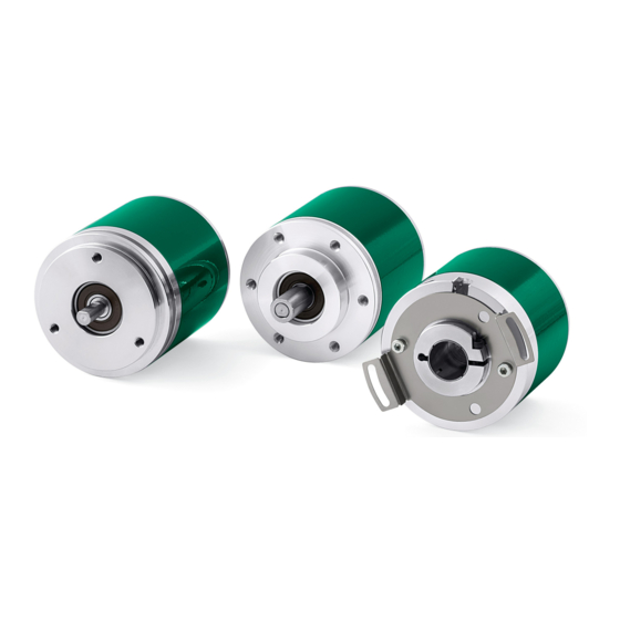
Smart encoders & actuators
ES58, ES58S
EM58, EM58S
ESC58/59/60
EMC58/59/60
• Singleturn and multiturn absolute rotary encoder
• MODBUS RTU interface (RS-485) with programming software
• Resolution 4,096 cpr (ES58), 4,096 cpr x 16,384 revolutions (EM58)
• Diagnostic LEDs
• IP67 protection rate
Suitable for the following models:
• ES5812/MB-..., ES58S12/MB-...
• ESC5812/MB-..., ESC5912/MB-...,
ESC6012/MB-...
• EM5812/16384MB-..., EM58S12/16384MB-...
• EMC5812/16384MB-...,
EMC5912/16384MB-...,
EMC6012/16384MB-...
Lika Electronic
User's guide
•
Tel. +39 0445 806600
Version RS-485
Table of Contents
•
info@lika.biz
12
14
15
20
30
50
65
85
•
www.lika.biz
Advertisement
Table of Contents

Related Manuals for Lika ES58 Series


Summary of Contents for Lika ES58 Series
-
Page 1: Table Of Contents
Safety summary • ES5812/MB-..., ES58S12/MB-... Identification • ESC5812/MB-..., ESC5912/MB-..., Mechanical installation ESC6012/MB-... Electrical connections • EM5812/16384MB-..., EM58S12/16384MB-... Quick reference • EMC5812/16384MB-..., MODBUS® interface EMC5912/16384MB-..., Programming parameters EMC6012/16384MB-... Programming examples Lika Electronic • Tel. +39 0445 806600 • info@lika.biz • www.lika.biz... - Page 2 Tous droits réservés. This document and information contained herein are the property of Lika Electronic s.r.l. and shall not be reproduced in whole or in part without prior written approval of Lika Electronic s.r.l. Translation, reproduction and total or partial modification (photostat copies, film and microfilm included and any other means) are forbidden without written authorisation of Lika Electronic s.r.l.
-
Page 3: General Contents
4.5.3 Termination resistor (Figure 3).........................29 5 Quick reference........................... 30 5.1 Getting started................................30 5.2 Configuring the encoder using the software tool by Lika Electronic..........31 5.3 Main page of the interface...........................32 5.3.1 Configuring the serial port – Connection to the encoder............33 Read Params...............................35 Write Holding..............................35... - Page 4 SW version................................38 HW version................................38 Status word.................................38 Alarm register..............................38 Machine data not valid..........................38 5.3.3 Reading the exception responses – Exception error..............39 Exception error..............................39 5.3.4 Reading / writing the Holding Registers.....................40 Counts per rev..............................41 Total resolution..............................41 Preset value.................................41 Offset value.................................41 Node address..............................41 Baud rate................................42 Operating parameters...........................42 Enable scaling function..........................42...
- Page 5 Watchdog enable............................74 Save parameters...............................74 Load default parameters..........................74 Perform counting preset..........................74 7.1.2 Input Register parameters.........................76 Alarms register [0000 hex]..........................76 Machine data not valid..........................76 Flash memory error............................76 Watchdog................................76 Current position [0001-0002 hex]......................77 Register 4 [0003 hex]............................77 Wrong parameters list [0004-0005 hex]....................77 DIP switch baud rate [0006 hex]......................78 DIP switch node ID [0007 hex]........................79...
-
Page 6: Subject Index
Subject Index Address dip switch............38 Load default parameters..........74 Alarm..................81 Alarm register..............38 Machine data not valid..........38, 76 Alarms register [0000 hex]...........76 Angle..................37 Node address..............41 Auto save................44 Offset value.................41 Baud rate................42 Offset value [0006-0007 hex]........71 Baud rate dip switch............37 Operating parameters............42 Operating parameters [0008 hex]......72 Change counting dir............42 Code sequence..............73 Perform counting preset..........74... -
Page 7: Typographic And Iconographic Conventions
In this guide, to make it easier to understand and read the text the following typographic and iconographic conventions are used: parameters and objects both of Lika device and interface are coloured in GREEN; • alarms are coloured in RED;... -
Page 8: Es5812/Mb
MODBUS interface. In this section the interface features and the registers implemented in the unit are fully described. In the “Quick reference” section on page 30 the software tool designed by Lika Electronic to easily configure the encoder via RS-485 serial port is fully described. -
Page 9: Glossary Of Modbus Terms
Glossary of MODBUS terms MODBUS, like many other networking systems, has a set of unique terminology. Table below contains a few of the technical terms used in this guide to describe the MODBUS interface. They are listed in alphabetical order. Address field It contains the Slave address. - Page 10 The function code field of a MODBUS data unit is coded in one byte. Valid codes are in the range of 1 ... 255 decimal (the range 128 – 255 is reserved and used for exception responses). Function code "0" is not valid. Lika devices only implement public function codes. Holding register In the MODBUS data model, a Holding register is the output data.
- Page 11 The Protocol Data Unit (PDU) is the MODBUS function code and data field. It is packed together with the Address Field and the CRC (or LRC) to form the Modbus Serial Line PDU. The MODBUS protocol defines three PDUs. They are: MODBUS Request PDU, mb_req_pdu •...
-
Page 12: Safety Summary
• elsewhere in this manual violates safety standards of design, manufacture, and intended use of the equipment; Lika Electronic assumes no liability for the customer's failure to comply • with these requirements. 1.2 Electrical safety Turn OFF the power supply before connecting the device;... -
Page 13: Mechanical Safety
ES58 • EM58 MODBUS® - minimize noise by connecting the shield and/or the connector housing and/or the frame to ground. Make sure that ground is not affected by noise. The connection point to ground can be situated both on the device side and on user’s side. -
Page 14: Identification
Information is listed in the delivery document too. Please always quote the order code and the serial number when reaching Lika Electronic for purchasing spare parts or needing assistance. For any information on the technical characteristics of the product refer to the technical catalogue. -
Page 15: Mechanical Installation
ES58 • EM58 MODBUS® Mechanical installation WARNING Installation and maintenance operations must be carried out by qualified personnel only, with power supply disconnected. Shaft and mechanical components must be in stop. For any information on the mechanical data and the electrical characteristics of the encoder please refer to the technical catalogue. -
Page 16: Installation Using Fixing Clamps (Code Lkm-386)
ES58 • EM58 MODBUS® 3.1.2 Installation using fixing clamps (code LKM-386) a [mm] b [mm] c [mm] d [mm] ES58, EM58 50 F7 ES58S, EM58S 36 H7 3.1.3 Installation using a mounting bell (code PF4256) ES58S, EM58S NOTE In order to guarantee reliability over time of the encoder mechanical parts, we recommend a flexible coupling to be installed between the encoder and the motor shaft. -
Page 17: Hollow Shaft Encoders (Esc58, Emc58, Esc59, Emc59, Esc60, Emc60)
• insert the anti-rotation pin 1 into the slot on the flange of the encoder; this secures it in place by grub screw 2, preset at Lika; • fix the collar 3 to the encoder shaft (apply threadlocker to screw 3). -
Page 18: Esc59, Emc59
ES58 • EM58 MODBUS® 3.2.2 ESC59, EMC59 • Mount the encoder on the motor shaft using the reducing sleeve 8 (if supplied). Avoid forcing the encoder shaft; • fasten the fixing plate 4 to the rear of the motor using two M3 cylindrical head screws 5;... -
Page 19: Esc60, Emc60
ES58 • EM58 MODBUS® 3.2.3 ESC60, EMC60 • Fix the tempered pin 6 to the rear of the motor; • mount the encoder on the motor shaft using the reducing sleeve 8 (if supplied). Avoid forcing the encoder shaft; • make sure the anti-rotation pin 6 is inserted properly into the fixing plate 7; •... -
Page 20: Electrical Connections
Modbus A (RS-485) Blue Modbus B (RS-485) 1 0Vdc of the RS-485 serial connection too. 4.1.1 CB cable specifications Model : LIKA CB type cable Wires : 2 x 0.24 mm (24/19AWG) + 2 x 0.35 mm (22/19AWG) pair cable Jacket... -
Page 21: M12 5-Pin Connector
Lika's E- connectors have a plastic gland, thus grounding is not possible. In the specific case pin 1 of M12 connector is specifically intended to allow the connection of the shield to ground. -
Page 22: Diagnostic Leds (Figure 1)
ES58 • EM58 MODBUS® 4.4 Diagnostic LEDs (Figure 1) Figure 1: Diagnostic LEDs Two bicoloured LEDs located in the rear side of the encoder (see the Figure here above) are meant to show visually the operating or fault status of the MODBUS MAN ESx58x_EMx58x MB E 1.2 Electrical connections 22 of 92... - Page 23 Please turn the device off and then on again. If the error is still on, please contact Lika Electronic After Sales Service. While performing the firmware upgrade operation (bootloading, refer to the “5.4 Update FW page - Firmware upgrade”...
- Page 24 ES58 • EM58 MODBUS® ACTIVITY STATUS/ERROR Description While downloading data to the flash memory for upgrading the firmware of the unit (see the “5.4 Update FW page - Firmware upgrade” section on page 45), if an error occurs which stops the upgrading process Blinking Blinking (for instance: a voltage drop and/or the...
-
Page 25: Dip Switches (Figure 2 And Figure 3)
ES58 • EM58 MODBUS® 4.5 DIP switches (Figure 2 and Figure 3) WARNING Power supply must be turned off before performing this operation! NOTE When performing this operation be careful not to damage the internal components and the connection wires. To access the DIP switches loosen and remove the M12 metal screw plug in the rear of the encoder. -
Page 26: Setting Data Transmission Rate: Baud Rate And Parity Bit (Figure 3)
ES58 • EM58 MODBUS® The DIP switches are located just beneath. Figure 3: DIP switches 4.5.1 Setting data transmission rate: Baud rate and Parity bit (Figure 3) WARNING Power supply must be turned off before performing this operation! Use the DIP switch A to set the data transmission rate (baud rate and parity bit). Set the binary value of the baud rate and the parity bit according to the following table, considering that: ON = 1;... -
Page 27: Setting The Node Address (Figure 3)
ES58 • EM58 MODBUS® EXAMPLE Set the baud rate to 9600 bits per second and Odd parity bit: Switches Position Value Set the baud rate to 115200 bits per second and Even parity bit: Switches Position Value The data transmission rate which is currently set in the unit can be read next to DIP switch baud rate [0006 hex] register, see on page 78. - Page 28 ES58 • EM58 MODBUS® The range of node addresses is between 1 and 247. The default address is 1. EXAMPLE Set the node address to 25: = 0001 1001 (binary value) Switches 1 Position ON OFF OFF ON ON OFF OFF OFF Value Set the node address to 55: = 0011 0111...
-
Page 29: Termination Resistor (Figure 3)
ES58 • EM58 MODBUS® 4.5.3 Termination resistor (Figure 3) WARNING Power supply must be turned off before performing this operation! Use the RT DIP switch to activate or deactivate the bus termination. The bus termination resistor must be activated as line termination in the first or the last device of the transmission line (both at the beginning and the end of the communication bus). -
Page 30: Quick Reference
• Setting data transmission rate: Baud rate and Parity bit (Figure 3)” section on page 26); the default value set by Lika Electronic at factory set-up is “baud rate = 19200 bit/s, parity = Even”; set the node address (node ID; see the “4.5.2 Setting the node address •... -
Page 31: Configuring The Encoder Using The Software Tool By Lika Electronic
ES58 • EM58 MODBUS® 5.2 Configuring the encoder using the software tool by Lika Electronic ES58 / EM58 series rotary encoders with MODBUS interface are supplied with a software expressly developed by Lika Electronic in order to easily programme and configure the devices. It allows the operator to set the working parameters of the device and monitor whether the devices are running properly. -
Page 32: Main Page Of The Interface
ES58 • EM58 MODBUS® 5.3 Main page of the interface To launch the program and configure the MODBUS encoder double-click the MODBUS-RTU.EXE executable file. The interface consists of a main page and two subpages. When the program starts, the main page will appear on the screen. The main page of the interface can be divided into seven parts. -
Page 33: Configuring The Serial Port - Connection To The Encoder
ES58 • EM58 MODBUS® 6. In the EXCEPTION ERROR group box just beneath, the exception response messages are shown, the Server transmits exception responses to the Client when an error occurs because the Server is not able to handle the request from the Client. For more information on the exception responses and the MODBUS exception codes please refer to the “7.2 Exception response and codes“... - Page 34 In the Address item of the DEVICE group box the MODBUS address of the connected device must be entered. By default the address of all Lika devices is “1”. If you do not know the MODBUS address of the networked device select the All addresses check box.
-
Page 35: Read Params
ES58 • EM58 MODBUS® If the connection succeeds, the Device connected message as well as the model of the connected device are displayed in the group box between the DEVICE and the FUNCTIONS group boxes. Actually the software is able to recognize automatically the model of the connected device and changes the lay-out of the software tool's pages consequently. -
Page 36: Reading The Input Registers
ES58 • EM58 MODBUS® register where the cursor is placed. After having set a new value next to any Holding Register, press the Write Holding button to transmit to the encoder all Holding Registers data; or just press the ENTER key to send only the datum of the Holding Register where the cursor is placed. -
Page 37: Continuous Reading
ES58 • EM58 MODBUS® In this group box the items listed hereafter are available. Continuous reading When you press the Continuous reading button you enable the transmission of continuous commands to read the Input Registers uninterruptedly. After pressing the button, its background is coloured orange and a green progress bar appears beneath the field to indicate that a reading operation is being executing. -
Page 38: Address Dip Switch
ES58 • EM58 MODBUS® Address dip switch It shows the node address that is currently set through the DIP switch B (it is expressed both in decimal notation -1 in the Figure- and by means of a picture). DIP switch node ID [0007 hex] See the register on page 79. -
Page 39: Reading The Exception Responses - Exception Error
ES58 • EM58 MODBUS® The input field of the specific wrong parameter in the HOLDING REGISTERS group box of the interface is highlighted in red. 5.3.3 Reading the exception responses – Exception error In the EXCEPTION ERROR group box just beneath the INPUT REGISTERS group box, the exception response messages that the Server transmits to the Client when an error occurs are shown. -
Page 40: Reading / Writing The Holding Registers
ES58 • EM58 MODBUS® 5.3.4 Reading / writing the Holding Registers In the largest group box on the right of the programming interface, the Holding Registers are available. The items in this group box allow to read in or write into the working parameters of the device, by pressing the Read Params and Write Holding buttons respectively, they are available in the DEVICE group box. -
Page 41: Counts Per Rev
ES58 • EM58 MODBUS® If the Auto save check box is not selected instead, you must press the Save parameters button to store the parameters permanently on the EEPROM after setting (see on page 44). In this section the items listed hereafter are available. Counts per rev It allows both to set a custom singleturn resolution of the device and to show Custom... -
Page 42: Baud Rate
ES58 • EM58 MODBUS® Baud rate As the data transmission rate can be set only via hardware (by means of the DIP switch), this parameter is not used. Operating parameters Operating parameters [0008 hex] It groups the functions available in the register (see on page 72) and shows their current enabling 1/disabling 0 state. -
Page 43: Execute Preset
ES58 • EM58 MODBUS® register will appear in the field on the left side. When the function is enabled, the text of the label is coloured yellow. For more information refer to the Watchdog enable parameter on page 74. Execute preset This button allows to activate the preset function in order to set the output value to the value entered next to the Preset value parameter (see on page 41). -
Page 44: Auto Save
ES58 • EM58 MODBUS® Auto save It enables / disables the autosave function. If the Auto save check box is selected, all the parameters of the Holding registers are stored automatically and instantaneously as soon as they are set: check box settings are saved as soon as the check box is selected / deselected; the write registers are saved as soon as you press the ENTER key in the keyboard or place the cursor anywhere outside the field after setting the value. -
Page 45: Update Fw Page - Firmware Upgrade
“user program”, is stored in the flash memory integrated inside the unit. These encoders are designed so that the firmware can be easily updated by the user himself. This allows Lika MAN ESx58x_EMx58x MB E 1.2... -
Page 46: Preliminary Operations And Connections
2. press the SELECT FILE button; once you press the button the Open dialogue box appears on the screen: open the folder where the firmware upgrading .BIN file released by Lika Electronic is located, select the file, and confirm by pressing the OPEN button;... - Page 47 ES58 • EM58 MODBUS® the encoder's enclosure start blinking red at 5 Hz with duty cycle = 50%; the encoder is now ready and waits for the firmware upgrade operation to start; WARNING As long as the encoder is in the boot mode and the firmware upgrading process has not started, you can restore the normal communication mode simply by switching the device off and then on again.
-
Page 48: Manual Frame Page - Transmitting Pdus Manually
ES58 • EM58 MODBUS® 5.5 Manual frame page – Transmitting PDUs manually When you press the Manual frame button in the FUNCTIONS group box on the top right of the main page of the interface, you enter the page that allows to enter and transmit Request PDUs manually. - Page 49 ES58 • EM58 MODBUS® When an error occurs because the Server is not able to handle the request from the Client (for example, if you confirm values that are not allowed or because of a request to read a non-existent output or register), the exception response messages that the Server transmits to the Client will be displayed next to the Exception error field at the bottom of the page.
-
Page 50: Modbus® Interface
ES58 • EM58 MODBUS® MODBUS® interface Lika ES58 / EM58 MODBUS series encoders are Slave devices and implement the MODBUS application protocol (level 7 of OSI model) and the “Modbus over Serial Line” protocol (levels 1 & 2 of OSI model). -
Page 51: Modbus Frame Description
ES58 • EM58 MODBUS® 6.2 MODBUS frame description The Modbus application protocol defines a simple Protocol Data Unit (PDU) independent of the underlying communication layers: Function code Data MODBUS PDU The mapping of Modbus protocol on a specific bus or network introduces some additional fields on the Protocol Data Unit. -
Page 52: Transmission Modes
The transmission mode and the serial port parameters must be the same for all devices on a Modbus Serial Line. All devices must implement the RTU mode, while the ASCII mode is an option. Lika devices only implement RTU transmission mode, as described in the following section. -
Page 53: Rtu Transmission Mode
ES58 • EM58 MODBUS® 6.3.1 RTU transmission mode When devices communicate on a Modbus serial line using the RTU (Remote Terminal Unit) mode, each 8-bit byte in a message contains two 4-bit hexadecimal characters. Each message must be transmitted in a continuous stream of characters. - Page 54 ES58 • EM58 MODBUS® The following drawing provides a description of the RTU transmission mode state diagram. Both “Master” and “Slave” points of view are expressed in the same drawing. Initial State Idle Transition from state needs an interval of at least •...
-
Page 55: Function Codes
Reserved function codes are not available for public use. 6.4.1 Implemented function codes Lika ES58 / EM58 Modbus series encoders only implement public function codes, they are described hereafter. 03 Read Holding Registers FC = 03 (03 hex) ro This function code is used to READ the contents of a contiguous block of holding registers in a remote device;... - Page 56 ES58 • EM58 MODBUS® Response PDU Function code 1 byte 03 hex Byte count 1 byte 2 x N* Register value N* x 2 bytes *N = Quantity of registers Exception Response PDU Error code 1 byte 83 hex (=03 hex + 80 hex) Exception code 1 byte 01 or 02 or 03 or 04...
-
Page 57: Read Input Register
ES58 • EM58 MODBUS® Preset value [0004-0005 The full frame needed for the request to read the hex] parameter (registers 5 and 6) to the Slave having the node address 1 is as follows: Request PDU (in hexadecimal format) [01][03][00][04][00][02][85][CA] where: [01] = Slave address [03] = 03 Read Holding Registers function code... - Page 58 ES58 • EM58 MODBUS® Request PDU Function code 1 byte 04 hex Starting address 2 bytes 0000 hex to FFFF hex Quantity of Input Registers 2 bytes 0000 hex to 007D hex Response PDU Function code 1 byte 04 hex Byte count 1 byte 2 x N*...
-
Page 59: Write Single Register
ES58 • EM58 MODBUS® Current position [0001- The full frame needed for the request to read the 0002 hex] parameter (input registers 2 and 3) to the Slave having the node address 1 is as follows: Request PDU (in hexadecimal format) [01][04][00][01][00][02][20][0B] where: [01] = Slave address... - Page 60 ES58 • EM58 MODBUS® Request PDU Function code 1 byte 06 hex Register address 2 bytes 0000 hex to FFFF hex Register value 2 bytes 0000 hex to FFFF hex Response PDU Function code 1 byte 06 hex Register address 2 bytes 0000 hex to FFFF hex Register value...
-
Page 61: Write Multiple Registers
ES58 • EM58 MODBUS® 9): bit 0 Scaling function = 1; bit 1 Code sequence = 0; the remaining bits are not used, therefore their value is 0. The full frame needed for the request to write the value 00 01 hex in the Operating parameters [0008 hex] item (register 9) to the Slave having the node address 1 is as follows:... - Page 62 ES58 • EM58 MODBUS® For the complete list of registers accessible using 16 Write Multiple Registers function code please refer to the “7.1.1 Machine data parameters (Holding registers)” section on page 65. Request PDU Function code 1 byte 10 hex Starting address 2 bytes 0000 hex to FFFF hex...
- Page 63 ES58 • EM58 MODBUS® Starting address Hi Starting address Hi Starting address Lo Starting address Lo Quantity of registers Hi Quantity of registers Hi Quantity of registers Lo Quantity of registers Lo Byte count Register 1 value Hi Register 1 value Lo Register 2 value Hi Register 2 value Lo Register 3 value Hi...
- Page 64 ES58 • EM58 MODBUS® [00][04] = number of requested registers [08] = number of bytes (2 bytes for each register) [00][00] = value to be set in the register 1 [08][00] = value to be set in the register 2, 00 00 08 00 hex = 2048 dec [00][80] = value to be set in the register 3 [00][00] = value to be set in the register 4, 00 80 00 00 hex = 8 388 608 dec [B6][DA] = CRC...
-
Page 65: Programming Parameters
ES58 • EM58 MODBUS® Programming parameters 7.1 Parameters available Hereafter the parameters available for the MODBUS encoders are listed and described as follows: Parameter name [Register address] [Register number, data types, attribute] The register address is expressed in hexadecimal notation. ... - Page 66 ES58 • EM58 MODBUS® These registers set the custom number of distinguishable steps per revolution that are output for the absolute position value (singleturn resolution). You are allowed to set whatever integer value lower than or equal to the maximum number of physical steps per revolution (4096 cpr). If you enter an out-of-range value (i.e.
-
Page 67: Custom Total Resolution [0002-0003 Hex]
ES58 • EM58 MODBUS® Custom total resolution [0002-0003 hex] If we do not change the value at the same time, we will get the following result: (Custom total resolution [0002- 67,108,864 0003 hex]) Number of revolutions = = 32,768 (Custom counts per revolution [0000- 2,048 0001 hex]) - Page 68 ES58 • EM58 MODBUS® The custom number of revolutions results from the following calculation: Custom total resolution [0002-0003 hex] Custom counts per revolution [0000-0001 hex] You are allowed to set whatever integer value lower than or equal to the overall hardware resolution (ES58: 4,096 counts = 12 bits;...
- Page 69 ES58 • EM58 MODBUS® Custom total resolution [0002-0003 hex] would be lower than the Custom counts per revolution [0000-0001 hex], however the above setting is accepted. WARNING Custom total If you have set the preset, when you change the value next to the resolution [0002-0003 hex] parameter, then you must check the value in the Preset value [0004-0005 hex]...
-
Page 70: Preset Value [0004-0005 Hex]
ES58 • EM58 MODBUS® Preset value [0004-0005 hex] [Registers 5-6, Unsigned32, rw] This register is intended to set the Preset value. The Preset function is meant to assign a desired value to a physical position of the encoder shaft. The chosen physical position will get the value set next to this item and all the previous and following positions will get a value according to it. -
Page 71: Offset Value [0006-0007 Hex]
ES58 • EM58 MODBUS® And so on. NOTE If the Scaling function is disabled (bit 0 in the Operating parameters [0008 hex] register= 0), Preset value [0004-0005 hex] must be lower than or equal to the total hardware resolution (i.e. hardware counts per revolution ... -
Page 72: Operating Parameters [0008 Hex]
ES58 • EM58 MODBUS® Operating parameters [0008 hex] [Register 9, Unsigned16, rw] Operating parameters [0008 hex] Byte structure of the register: byte … … Byte 0 Scaling function bit 0 This bit is meant to enable / disable the scaling parameters Custom counts per revolution [0000-0001 hex] Custom total resolution [0002-0003 hex]. -
Page 73: Code Sequence
ES58 • EM58 MODBUS® Code sequence The Code sequence command is intended to set whether bit 1 the encoder position value increases (count up information) when the shaft is rotating clockwise (CW) or when the shaft is rotating counter-clockwise (CCW). CW and CCW rotations are viewed from the shaft end. -
Page 74: Watchdog Enable
(“1”). Load default parameters bit 10 Default parameters (they are set at the factory by Lika Electronic engineers to allow the operator to run the device for standard operation in a safe mode) are restored at each rising edge of the bit; in other words, the default parameters uploading operation is performed each time this bit is switched from logic level low (“0”) to logic level high... - Page 75 ES58 • EM58 MODBUS® sent, the current encoder position is temporarily saved in Offset value [0006-0007 hex] register. For any further information on the preset function and the meaning Preset and use of the related registers and commands value [0004-0005 hex], Offset value [0006-0007 hex] and Perform counting preset refer to page 70.
-
Page 76: Input Register Parameters
ES58 • EM58 MODBUS® 7.1.2 Input Register parameters Input Register parameters are accessible for reading only; to read the value set in an input register parameter use the 04 Read Input Register function code (reading of multiple input registers); for any further information on the implemented function codes refer to the “6.4.1 Implemented function codes“... -
Page 77: Current Position [0001-0002 Hex]
ES58 • EM58 MODBUS® second, the system forces an alarm condition (the Watchdog alarm bit is activated). The alarm is invoked to appear as soon as the Modbus network communication is restored. The Watchdog function is a safety timer that uses a time-out to detect loop or deadlock conditions. -
Page 78: Dip Switch Baud Rate [0006 Hex]
ES58 • EM58 MODBUS® Parameter Not used Custom counts per revolution [0000-0001 hex] Custom total resolution [0002-0003 hex] Preset value [0004-0005 hex] Offset value [0006-0007 hex] Operating parameters [0008 hex] DIP switch node ID [0007 hex] DIP switch baud rate [0006 hex] 8 …... -
Page 79: Dip Switch Node Id [0007 Hex]
ES58 • EM58 MODBUS® DIP switch node ID [0007 hex] [Register 8, Unsigned16, ro] This is meant to show the node address set in the unit; node address has to be set through the provided DIP switch. For any further information on setting the node ID refer to the “4.5.2 Setting the node address (Figure 3)”... -
Page 80: Status Word [000A Hex]
ES58 • EM58 MODBUS® Status word [000A hex] [Register 11, Unsigned16, ro] This register contains information about the current state of the device. The eight bits of Byte 0 (LSB) are meant to show the values that are currently set in Operating parameters [0008 hex] register Byte 0 (LSB);... -
Page 81: Alarm
ES58 • EM58 MODBUS® Alarm bit 8 If the value is “=1” there is an active alarm, see details Alarms register [0000 hex] in the variable on page bits 9 … 15 Not used. MAN ESx58x_EMx58x MB E 1.2 Programming parameters 81 of 92... -
Page 82: Exception Response And Codes
ES58 • EM58 MODBUS® 7.2 Exception response and codes When a Client device sends a request to a Server device it expects a normal response. One of four possible events can occur from the Master's query. If the Server device receives the request without a communication error •... - Page 83 ES58 • EM58 MODBUS® NOTE Please note that here follows the list of the exception codes indicated by MODBUS but not necessarily supported by the manufacturer. MODBUS Exception codes Code Name Meaning ILLEGAL FUNCTION The function code received in the query is not an allowable action for the server.
- Page 84 ES58 • EM58 MODBUS® ACKNOWLEDGE Specialized use in conjunction with programming commands. The server has accepted the request and is processing it, but a long duration of time will be required to do so. This response is returned to prevent a timeout error from occurring in the client.
-
Page 85: Programming Examples
ES58 • EM58 MODBUS® Programming examples Hereafter are some examples of both reading and writing parameters. All values are expressed in hexadecimal notation. 8.1 Using the 03 Read Holding Registers function code EXAMPLE 1 Preset value [0004-0005 hex] Request to read the parameter (registers 5 and 6) to the Slave having the node address 1. -
Page 86: Using The 04 Read Input Register Function Code
ES58 • EM58 MODBUS® 8.2 Using the 04 Read Input Register function code EXAMPLE 1 Current position [0001-0002 hex] Request to read the parameter (registers 2 and 3) to the Slave having the node address 1. Request PDU (in hexadecimal notation) [01][04][00][01][00][02][20][0B] where: [01] = Slave address... -
Page 87: Using The 06 Write Single Register Function Code
ES58 • EM58 MODBUS® 8.3 Using the 06 Write Single Register function code EXAMPLE 1 Operating parameters [0008 hex] Request to write in the register (register 9) to the Slave having the node address 1: we need to set the scaling function (Scaling function = 1) and the count up information with clockwise rotation of the encoder shaft (Code sequence = 0). -
Page 88: Using The 16 Write Multiple Registers Function Code
ES58 • EM58 MODBUS® 8.4 Using the 16 Write Multiple Registers function code EXAMPLE 1 Custom Request to write the value 00 00 08 00 hex (=2,048 dec) next to the counts per revolution [0000-0001 hex] parameter (registers 1 and 2) and the Custom total resolution value 00 80 00 00 hex (= 8,388,608 dec) next to the [0002-0003 hex]... -
Page 89: Default Parameters List
ES58 • EM58 MODBUS® Default parameters list 9.1 List of the Holding Registers with default value Registers list and address Default value Custom counts per revolution 4,096 [0000-0001 hex] Custom total resolution 67,108,864 [0002-0003 hex] Preset value [0004-0005 hex] Offset value [0006-0007 hex] Scaling function in Operating parameters [0008 hex]... - Page 90 This page intentionally left blank...
- Page 91 This page intentionally left blank...
- Page 92 Ce dispositif doit être alimenté par un circuit de Classe 2 ou à très basse tension ou bien en appliquant une tension maxi de 30Vcc. Voir le code de commande pour la tension d'alimentation. Lika Electronic Via S. Lorenzo, 25 • 36010 Carrè (VI) •...
Need help?
Do you have a question about the ES58 Series and is the answer not in the manual?
Questions and answers