Table of Contents
Advertisement
Quick Links
Smart encoders & actuators
IP58
IQ58
IQ36
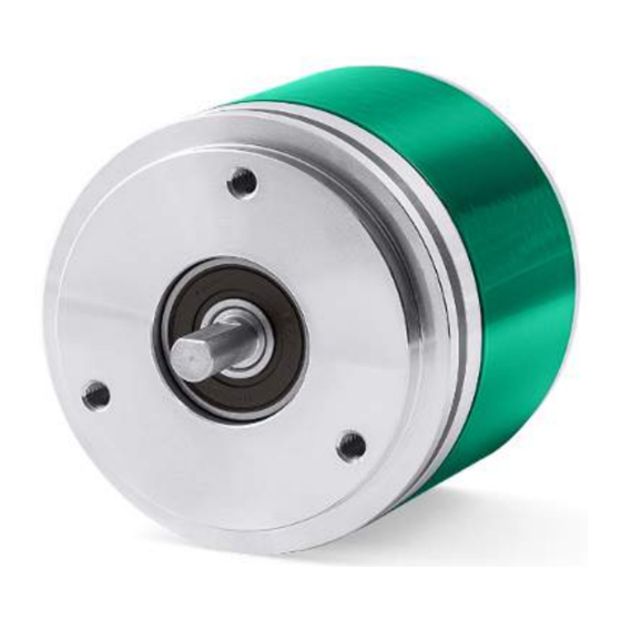
• Programmable incremental encoder
• IP58 high resolution encoder for demanding applications
• IQ58 general purpose encoder for standard applications
• IQ36 compact encoder for critical applications
• Resolution from 1 to 65,536 PPR
• Output voltage +5Vdc or +10Vdc + 30Vdc (selectable)
• USB connection kit available for configuration
Suitable for the following models:
•
•
•
•
•
•
Lika Electronic
User's guide
•
Tel. +39 0445 806600
Table of Contents
•
info@lika.biz
10
11
18
28
40
•
www.lika.biz
7
8
Advertisement
Table of Contents

Related Manuals for Lika IP58


Summary of Contents for Lika IP58
-
Page 1: Table Of Contents
IP58 IQ58 IQ36 • Programmable incremental encoder • IP58 high resolution encoder for demanding applications • IQ58 general purpose encoder for standard applications • IQ36 compact encoder for critical applications • Resolution from 1 to 65,536 PPR • Output voltage +5Vdc or +10Vdc + 30Vdc (selectable) •... - Page 2 Tous droits réservés. This document and information contained herein are the property of Lika Electronic s.r.l. and shall not be reproduced in whole or in part without prior written approval of Lika Electronic s.r.l. Translation, reproduction and total or partial modification (photostat copies, film and microfilm included and any other means) are forbidden without written authorisation of Lika Electronic s.r.l.
-
Page 3: General Contents
1.3 Mechanical safety..............................9 2 Identification............................10 3 Mechanical installation........................11 3.1 Encoder with solid shaft IP58, IP58S / IQ58, IQ58S................11 3.1.1 Customary installation..........................11 3.1.2 Installation using fixing clamps (optional kit code LKM-386)...........12 3.1.3 Installation using a mounting bell (optional kit code PF4256)..........12 3.2 Encoder with solid shaft IQ36..........................13... - Page 4 rpm...................................37 Encoder status..............................38 5.5 Diagnostics page..............................39 6 Default parameters list........................40...
-
Page 5: Subject Index
Subject Index Encoder status..............38 180° el (gated A)...............35 Index length...............35 Index position..............35 2250..................37 INTERFACE TYPE..............30 Internal pos. register............31 4500..................37 Max rpm................37 5-30V (PP/LD universal)..........36 5V (line driver/TTL)............36 NO ERROR................38 90° el (gated A, B)............35 Output circuit..............36 9000..................37 READ.................38 e seg. ADVANCED DIAGNOSTICS..........38 Resolution................31 BACK TO MAIN PAGE............39... -
Page 6: Typographic And Iconographic Conventions
In this guide, to make it easier to understand and read the text the following typographic and iconographic conventions are used: parameters and objects both of Lika device and interface are coloured in GREEN; • alarms are coloured in RED;... -
Page 7: Ip58, Ip58S
0 signal is output, but also choose for instance the voltage level of A, B and 0 output channels. IP58 / IQ58 / IQ36 programmable encoders are available in both solid (IP58, IP58S, IQ58, IQ58S, IQ36) and hollow (CKP58; CKP59; CKP60, CKQ58, CKQ59, CKQ60, CKQ36) shaft versions. -
Page 8: Safety Summary
• elsewhere in this manual violates safety standards of design, manufacture, and intended use of the equipment; Lika Electronic assumes no liability for the customer's failure to comply • with these requirements. 1.2 Electrical safety Turn OFF power supply before connecting the device;... -
Page 9: Mechanical Safety
IP58, IQ58, IQ36 - minimize noise by connecting the shield and/or the connector housing and/or the frame to ground. Make sure that ground is not affected by noise. The connection point to ground can be situated both on the device side and on user’s side. -
Page 10: Identification
Information is listed in the delivery document too. Please always quote the order code and the serial number when reaching Lika Electronic for purchasing spare parts or needing assistance. For any information on the technical characteristics of the product refer to the technical catalogue. -
Page 11: Mechanical Installation
3.1 Encoder with solid shaft IP58, IP58S / IQ58, IQ58S • Mount the flexible coupling 1 on the encoder shaft; • fix the encoder to the flange 2 (or to the mounting bell) by means of the screws 3;... -
Page 12: Installation Using Fixing Clamps (Optional Kit Code Lkm-386)
IP58, IQ58, IQ36 3.1.2 Installation using fixing clamps (optional kit code LKM-386) [mm] [mm] [mm] [mm] IP58, IQ58 50 F7 IP58S, IQ58S 36 H7 3.1.3 Installation using a mounting bell (optional kit code PF4256) MAN IP58_IQ58_IQ36 E 1.6 Mechanical installation... -
Page 13: Encoder With Solid Shaft Iq36
IP58, IQ58, IQ36 3.2 Encoder with solid shaft IQ36 • Mount the flexible coupling 1 on the encoder shaft; • fix the encoder to the flange 2 by means of the screws 3; • mount the flexible coupling 1 on the motor shaft, then secure the flange 2 either to the motor or to the mounting support;... -
Page 14: Encoder With Hollow Shaft Ckp58 / Ckq58
Avoid forcing the encoder shaft; • insert the anti-rotation pin 1 into the slot on the flange of the encoder; this secures it in place by grub screw 2, preset at Lika; • fix the collar 3 to the encoder shaft. -
Page 15: Ckp59, Ckq59 Installation Using The Fixing Plate
IP58, IQ58, IQ36 3.3.2 CKP59, CKQ59 installation using the fixing plate • Remove the antirotation pin 1 (see the Figure in the previous page); • mount the encoder on the motor shaft using the reducing sleeve 8 (if supplied). Avoid forcing the encoder shaft;... -
Page 16: Ckp60, Ckq60 Installation Using The Antirotation Pin And The Fixing Plate
IP58, IQ58, IQ36 3.3.3 CKP60, CKQ60 installation using the antirotation pin and the fixing plate • Remove the antirotation pin 1 (see the Figure on page 14); • fix the tempered pin 6 to the rear of the motor; • mount the encoder on the motor shaft using the reducing sleeve 8 (if supplied). -
Page 17: Encoder With Hollow Shaft Ckq36
IP58, IQ58, IQ36 3.4 Encoder with hollow shaft CKQ36 • Mount the encoder on the motor shaft. Avoid forcing the encoder shaft; • fasten the fixing plate 4 to the rear of the motor using two M3 x 8 cylindrical head screws 5;... -
Page 18: Electrical Connection
Counting direction Blue Black Shield Shield Case Case Only available on IP58 and IQ58 series Only available on IP- and CKP- models 4.2 T12 cable specifications Model : LIKA T12 cable Cross section : 4 x 0.25 mm + 4 x 2 x 0.14 mm... -
Page 19: M23 12-Pin Connector Specifications
IP58, IQ58, IQ36 4.3 M23 12-pin connector specifications M23 12-pin connector Male Clockwise Only available on IP58 and IQ58 series 4.4 M12 12-pin connector specifications Male Frontal side A coding MAN IP58_IQ58_IQ36 E 1.6 Electrical connection 19 / 44... -
Page 20: Connection Of The Shield
IP58, IQ58, IQ36 4.5 Connection of the shield For signals transmission always use shielded cables. The cable shielding must be connected properly to the metal ring nut 3 of the connector in order to ensure a good earthing through the frame of the device. To do this disentangle and shorten the shielding 1 and then bend it over the part 2;... -
Page 21: Index Pulse Setting Input (Ip-, Ckp- Models Only)
IP58, IQ58, IQ36 4.8 Index pulse setting input (IP-, CKP- models only) NOTE The Index pulse setting input is only available on IP-, CKP- models. This encoder provides the zero signal (Index pulse) once per revolution as relative positioning reference (home position, see the Figure here above). In this way a unique position can be identified at a well-known point in the 360°... -
Page 22: Counting Direction Input (Ip-, Ckp- Models Only)
IP58, IQ58, IQ36 4.9 Counting direction input (IP-, CKP- models only) NOTE The Counting direction input is only available on IP-, CKP- models. By default the phase relationship between A and B channels is so that the rising edge of A channel leads the rising edge of B channel when the encoder is rotating in a clockwise direction (see the “4.7 AB0, /AB0 output channels”... -
Page 23: Diagnostic Leds (Figure 1) (Ip-, Ckp- Models Only)
IP58, IQ58, IQ36 4.10 Diagnostic LEDs (Figure 1) (IP-, CKP- models only) NOTE The Diagnostic LEDs are only available on IP-, CKP- models. Two LEDs located in the rear side of the encoder enclosure are intended to show visually the work status of the device as explained in the following table. - Page 24 IP58, IQ58, IQ36 the encoder enclosure allows to set the point in the revolution at which the 0 pulse will be output. This function is useful, for example, when you want the zero position of the encoder and the zero mechanical position of the axis to match.
-
Page 25: I2C (Inter Integrated Circuit) Serial Connection
KIT IP/IQ58. ZCZ connection devices need the kit to be matched with a cable - M23 12-pin female connector cordset, EC-IP/IQ-M23 order code (only available for IP58 and IQ58 series); ZCM connection devices need the kit to be matched with a cable - M12 12-pin female connector cordset, EC-IP/IQ-M12 order code. -
Page 26: Installing The Kit Ip/Iq58 Usb Drivers
IP58, IQ58, IQ36 WARNING Please make sure that only one encoder is connected to the KIT IP/IQ58 when you activate the USB connection ! NOTE Before configuring the encoder by means of the programming interface, you must connect it to the personal computer through the KIT IP/IQ58 connection cable. - Page 27 IP58, IQ58, IQ36 2. connect the cable fitted with the USB connector to a USB socket of your PC; after a few seconds a message will appear in the notification area of the Windows taskbar and the USB Serial Converter drivers installation wizard will start.
-
Page 28: Programming Interface
From v2.5 up to … The new programming interface (from v2.0 release on) allows the connection to both the IP58 series and the IQ58 series using either the KIT IP58 (if you already have one) or the KIT IP/IQ58. The programming interface (from v2.5 release on) allows also the connection to the IQ36 series using either the KIT IP58 (if you already have one) or the KIT IP/IQ58. -
Page 29: Starting The Program
(Inter Integrated Circuit) serial interface. To communicate with the encoder, you must connect the device to the personal computer through a USB port using the specific connection kit order code KIT IP/IQ58 supplied by Lika Electronic. For any further information please refer to the “4.12 I2C (Inter Integrated Circuit) serial connection”... -
Page 30: Connection With The Encoder
5.3 Connection with the encoder When you start the program, the system automatically recognizes the type of interface you plugged into (INTERFACE TYPE: “KIT IP58” or “KIT IP/IQ58”). No action is required. You must select the series of the encoder you need to connect to instead. To do this open the ENCODER drop-down box and select from the options in the list: “IP58, IP58S, CKP58”... -
Page 31: Setting The Parameters
(x 1, x 2 or x 4) of the subsequent electronics before entering a new resolution value. Default = 1024 (min. value = 1; max. value = 65536) - IP58 series Default = 1024 (min. value = 1; max. value = 16384) - IQ58 and IQ36 series MAN IP58_IQ58_IQ36 E 1.6... - Page 32 IP58, IQ58, IQ36 EXAMPLES Here are some examples useful for better understanding the application field of the programmable resolution. We assume that the pulse multiplication factor in the following electronics is x 1. Example 1 Let's assume that the encoder is mounted on the driven draw roller of a slitter and the circumference of the roller is 753 mm.
-
Page 33: Counting Direction
IP58, IQ58, IQ36 As we know the reduction ratio of the reduction gearbox, we can set a suitable resolution in order to control the motion of the motor precisely and calculate the input speed starting from the known output speed. - Page 34 IP58, IQ58, IQ36 counter-clockwise direction (otherwise the count down when the encoder is Counting direction = CW to have the rotating in a clockwise direction). Set Counting direction increasing count when the shaft is turning clockwise; set CCW to have the increasing count when the shaft is turning counter-clockwise.
-
Page 35: Index Length
IP58, IQ58, IQ36 Index length This parameter allows to set the width of the Index pulse (0 pulse) expressed in electrical degrees. Two options are available and selectable in the drop-down box: 90° el (gated A, B) and 180° el (gated A). Please note that the 0 pulse... -
Page 36: Output Circuit
IP58, IQ58, IQ36 WARNING Please check the position of the 0 pulse and set it if necessary whenever you set Resolution a new resolution next to the parameter or reverse the counting direction. NOTE Index length The width of the 0 pulse can be set next to the parameter. -
Page 37: Max Rpm
IP58 encoder; or the rotational speed and the edge distance in the case of the IQ58/IQ36 encoders), depending on the maximum speed the application is able to reach. -
Page 38: Encoder Status
IP58, IQ58, IQ36 If you reverse the formula you can easily calculate the maximum number of revolutions starting from the value of the counting frequency (as allowed by the encoder, permitted by the subsequent electronics and accepted by the cable run) -
Page 39: Diagnostics Page
If an error occurs and the system is not able to solve it by pressing the CLEAR ERROR button, please take note of the error code that appears in the window and reach Lika Electronic's After Sales and Technical Service. Press the BACK TO MAIN PAGE button to display back the main page. -
Page 40: Default Parameters List
- IQ36 * 1024 PPR is the default resolution of the PROG order code version only, for instance: IP58-H-PROGZCZ48RL2. Versions with factory preset resolution may provide different PPR information, see your specific order code in the label applied to the encoder enclosure, for instance: CKP58-H-1000ZCM415RL2 (in this case: preset resolution = 1000 PPR). - Page 41 This page intentionally left blank...
- Page 42 This page intentionally left blank...
- Page 43 This page intentionally left blank...
- Page 44 Ce dispositif doit être alimenté par un circuit de Classe 2 ou à très basse tension ou bien en appliquant une tension maxi de 30Vcc. Voir le code de commande pour la tension d'alimentation. Lika Electronic Via S. Lorenzo, 25 •...
Need help?
Do you have a question about the IP58 and is the answer not in the manual?
Questions and answers