Table of Contents
Advertisement
Available languages
Available languages
Quick Links
IF51
Manuale d'uso
IF51
Descrizione
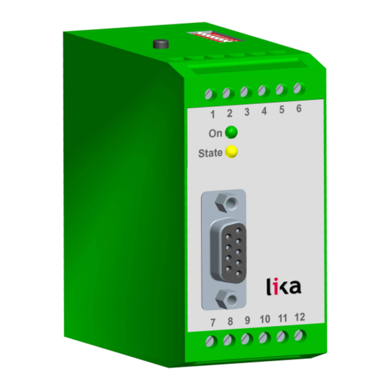
IF51 è un convertitore compatto ed economico e tuttavia estremamente
performante adatto per tutte le applicazioni industriali in cui l'informazione
trasmessa da un sensore o un encoder con interfaccia SSI debba essere
convertita in un segnale analogico oppure in una stringa dati in formato seriale
RS-232/RS-485.
L'unità è stata progettata per ospitare in un alloggiamento di dimensioni
contenute una morsettiera a 12 poli e un connettore SUB-D 9 poli femmina. La
custodia si presta all'installazione con sistema di fissaggio secondo le norme
DIN.
Elenco sezioni
1 - Norme di sicurezza
2 - Identificazione
3 - Introduzione
4 - Istruzioni di montaggio
5 - Connessioni elettriche
6 - Impostazione degli switch DIL
7 - Messa in servizio
8 - Lettura della posizione encoder mediante interfaccia seriale
9 - Configurazione da PC mediante il software operatore OS3.2
10 - Parametri di impostazione
11 - Programmazione libera della linearizzazione
12 - Funzioni di test
13 - Lista parametri
MAN IF51 I_E 1.1.odt
Manuale d'uso
1 / 56
Advertisement
Table of Contents

Related Manuals for Lika IF51


Summary of Contents for Lika IF51
- Page 1 Manuale d'uso IF51 Descrizione IF51 è un convertitore compatto ed economico e tuttavia estremamente performante adatto per tutte le applicazioni industriali in cui l'informazione trasmessa da un sensore o un encoder con interfaccia SSI debba essere convertita in un segnale analogico oppure in una stringa dati in formato seriale RS-232/RS-485.
- Page 2 è considerato una violazione delle norme di sicurezza standard previste dal costruttore o richieste dall'uso per cui lo strumento è destinato; • Lika Electronic s.r.l. non si assume alcuna responsabilità per eventuali danni o lesioni derivanti dall'inosservanza delle norme di sicurezza da parte dell'utilizzatore.
- Page 3 Citare sempre il codice di ordinazione e il numero di serie quando si contatta Lika Electronic s.rl. per l'acquisto di un ricambio o nella necessità di assistenza tecnica. Per ogni informazione sulle caratteristiche tecniche del dispositivo fare riferimento al catalogo del prodotto.
- Page 4 ATTENZIONE Effettuare il montaggio meccanico esclusivamente in assenza di tensione. Il convertitore IF51 deve essere installato e protetto all'interno di un quadro elettrico. Dispone di sistema di fissaggio secondo le norme DIN e può perciò essere agevolmente montato su guide DIN mediante le clip predisposte nella parte posteriore che non richiedono ulteriori supporti.
- Page 5 200 mA. 5.1 Collegamento dell'encoder in modalità Master Raccomandiamo di collegare la calza del cavo dell'encoder al polo negativo dell'alimentazione dell'encoder su entrambi i lati. MAN IF51 I_E 1.1.odt 5 - Connessioni elettriche 5 / 56...
- Page 6 IF51 5.2 Collegamento dell'encoder in modalità Slave In questa modalità il convertitore IF51 funziona in parallelo a un'altra apparecchiatura, ponendosi, per così dire, “in ascolto” della comunicazione dati esistente. In base alle necessità, il potenziale di riferimento del Master può essere collegato al morsetto 12 (GND) oppure rimanere non collegato, utilizzando così...
- Page 7 485; tuttavia è possibile utilizzarne una sola per volta. La comunicazione seriale permette la lettura della posizione dell'encoder e l'impostazione dei parametri e delle variabili da PC, secondo la necessità. MAN IF51 I_E 1.1.odt 5 - Connessioni elettriche 7 / 56...
- Page 8 IF51 MAN IF51 I_E 1.1.odt 5 - Connessioni elettriche 8 / 56...
- Page 9 Al termine dell'operazione di configurazione, avere cura di ripristinare lo switch DIL 6 TEST SSI nella posizione ON. Se impostato a OFF, anche un tocco involontario del pulsante TEACH porterebbe alla cancellazione delle precedenti impostazioni! MAN IF51 I_E 1.1.odt 6 - Impostazione degli switch DIL 9 / 56...
- Page 10 Tuttavia, in modalità Master, il test non è in grado di indicare i segnali di clock difettosi né l'errato cablaggio degli ingressi clock. MAN IF51 I_E 1.1.odt 7 - Messa in servizio 10 / 56...
- Page 11 BASSO. Questa funzione può rivelarsi estremamente utile per ogni necessità di test e di messa in funzione. L'ingresso SET utilizza stadi PNP / HTL (BASSO = aperto o 0–3V, ALTO = 10–30V). MAN IF51 I_E 1.1.odt 7 - Messa in servizio 11 / 56...
- Page 12 1a.pdf che può essere scaricato dal sito web di Lika Electronic. Il codice di accesso seriale per la lettura della posizione encoder è „ :8 “ . (caratteri ASCII per i due punti e 8) MAN IF51 I_E 1.1.odt8 - Lettura della posizione encoder mediante interfaccia seriale 12 / 56...
- Page 13 / Bit di stop 1 Se si ignorassero le impostazioni della seriale dell'unità, è possibile • avviare la funzione SCAN nel menu TOOLS per rilevarle. MAN IF51 I_E 1.1.odt9 - Configurazione da PC mediante il software operatore OS3.2 13 / 56...
- Page 14 I dati acquisiti mediante la procedura Teach premere il tasto READ. Tutti i valori saranno poi memorizzati nell'unità mediante la pressione del tasto STORE EEPROM. MAN IF51 I_E 1.1.odt 10 - Parametri di impostazione 14 / 56...
- Page 15 All'interno di questa nuova definizione del range round loop, si ha la libertà di impostare nuovamente la soglia iniziale zero e il valore full scale (cioè finale) Teach Minimum Teach Maximum. dell'uscita analogica mediante i parametri MAN IF51 I_E 1.1.odt 10 - Parametri di impostazione 15 / 56...
- Page 16 Round Loop nella Figura in basso, è necessario impostare il registro alla risoluzione completa dell'encoder e quindi spostare la transizione zero SSI Offset impostando il parametro di conseguenza. MAN IF51 I_E 1.1.odt 10 - Parametri di impostazione 16 / 56...
- Page 17 Teach Maximum dell'encoder (valore sempre positivo); nel parametro (Output Mode risoluzione massima dell'encoder. In tutti gli altri casi = 1, 2 o 3) MAN IF51 I_E 1.1.odt 10 - Parametri di impostazione 17 / 56...
- Page 18 (bit blanking function). Si veda il paragrafo “Considerazioni sull'uso della funzione di soppressione dei bit (bit blanking function)” alla pagina seguente. Deve essere impostato a “01” perché siano considerati tutti i bit encoder. MAN IF51 I_E 1.1.odt 10 - Parametri di impostazione 18 / 56...
- Page 19 0 a 180º; e di nuovo lo stesso numero di informazioni 0 – 4095 nella successiva seconda parte di rotazione da 180º a 360º. La risoluzione rimane invariata per quanto concerne il numero di informazioni per giro. MAN IF51 I_E 1.1.odt 10 - Parametri di impostazione 19 / 56...
- Page 20 Soprattutto nel caso di applicazioni con cicli di controllo ad anello chiuso, potrebbe risultare molto vantaggioso avere degli aggiornamenti dell'uscita analogica con ciclo fisso (switch DIL 7 0-20mA / 4-20mA out = OFF). Questo è MAN IF51 I_E 1.1.odt 10 - Parametri di impostazione 20 / 56...
- Page 21 Questa funzione permette di eseguire test e prove parametro simulate durante la messa in servizio dell'unità utilizzando valori fissi per l'uscita analogica. Si veda il paragrafo “7.4 Ingresso SET” a pagina 11. MAN IF51 I_E 1.1.odt 10 - Parametri di impostazione 21 / 56...
- Page 22 +/- 100mV oppure +/- 200 µA rispettivamente. Analogue Gain Questo parametro imposta il livello d'uscita massimo dell'uscita analogica. Impostando 1000 si ha un livello di uscita di 10 V o 20 mA rispettivamente. MAN IF51 I_E 1.1.odt 10 - Parametri di impostazione 22 / 56...
- Page 23 9600 4800 2400 1200 19200 38400 Serial Format Impostazione Bit di dati Parità Bit di stop 0 (default) pari pari dispari dispari nessuna nessuna pari dispari nessuna nessuna MAN IF51 I_E 1.1.odt 10 - Parametri di impostazione 23 / 56...
- Page 24 P16(x) impostare il parametro a –100% e il parametro a +100% . Questo permette all'utilizzatore di definire anche curve non simmetriche nei piani cartesiani rispetto all'asse zero. MAN IF51 I_E 1.1.odt 11 - Programmazione libera della linearizzazione 24 / 56...
- Page 25 Quando si utilizza la funzione OSCILLOSCOPE del software operatore, è necessario impostare il codice seriale „ :1 “ per registrare il valore d'uscita analogico. MAN IF51 I_E 1.1.odt 11 - Programmazione libera della linearizzazione 25 / 56...
- Page 26 • impostazione degli switch DIL; • tensioni di alimentazione interne; • stato uscita analogica. • Inoltre si possono registrare i seguenti registri utilizzando la funzione MONITOR: MAN IF51 I_E 1.1.odt 12 - Funzioni di test 26 / 56...
-
Page 27: Table Of Contents
+/- 6 P16(x) -100.000 +100.000 100000 +/- 6 P16(y) -100.000 +100.000 100000 +/- 6 Direction Analogue Offset +/-2 Analogue Gain 10000 1000 Unit Number Serial Baud Rate Serial Format MAN IF51 I_E 1.1.odt 13 - Lista parametri 27 / 56... - Page 28 Teach Minimum, Teach Maximum, Output Mode e esempi di impostazione Lika Electronic Via S. Lorenzo, 25 - 36010 Carrè (VI) - Italy Tel. +39 0445 806600 Fax +39 0445 806699 Italy: eMail info@lika.it - www.lika.it World: eMail info@lika.biz - www.lika.biz...
- Page 29 User's manual IF51 Description IF51 is the small, low-cost yet high-performing converter for industrial applications suitable for use in installations where the information delivered by a sensor or encoder fitted with SSI interface needs to be converted into an analogue signal or into a serial RS-232/RS-485 data format.
-
Page 30: Safety Summary
• elsewhere in this manual violates safety standards of design, manufacture, and intended use of the equipment; Lika Electronic s.r.l. assumes no liability for the customer's failure to • comply with these requirements. 1.2 Electrical safety Turn OFF power supply before connecting the device;... -
Page 31: Identification
SSI interface (6 to 25 bits of resolution with binary or Gray code) can be connected to IF51. The unit can operate in either Master mode (clock signal is generated by IF51 unit) or in Slave mode (clock signal is generated by a remote device). -
Page 32: Mounting Instructions
WARNING Mount the unit with power supply disconnected. IF51 converter must be installed and protected inside the electric panel. It provides DIN rail mounting and can quickly snap onto a DIN rail with built-in DIN rail clips that require no additional brackets or supports. -
Page 33: Electrical Connections
200 mA. 5.1 Encoder connections with Master operation We recommend the shield to be connected to the Minus wire of the encoder supply voltage on both sides. MAN IF51 I_E 1.1.odt 5 - Electrical connections 33 / 56... - Page 34 IF51 5.2 Encoder connections with Slave operation In this mode IF51 converter operates in parallel to another unit, acting as a „listener“ to the existing data communication. Quite according to need, the common potential of the master can be connected to terminal 12 (GND) or remain open for fully differential operation.
- Page 35 IF51 MAN IF51 I_E 1.1.odt 5 - Electrical connections 35 / 56...
-
Page 36: Dil Switch Settings
After set-up and commissioning, please set DIL switch 6 SSI-TEST to ON. If set to OFF, any even just unintentional touch of the TEACH button will cause your previous scaling input to be overwritten! MAN IF51 I_E 1.1.odt 6 - DIL switch settings 36 / 56... -
Page 37: Commissioning
Master mode, the result is only intended to show that the internal generation of the clock works properly. However, with Master mode, this test cannot indicate faulty clock drivers or bad wiring of the clock lines. MAN IF51 I_E 1.1.odt 7 - Commissioning 37 / 56... - Page 38 This function can be very useful for testing and commissioning purposes. The SET input uses PNP / HTL characteristics (LOW = open or 0 – 3 V, HIGH = 10 – 30 V). MAN IF51 I_E 1.1.odt 7 - Commissioning 38 / 56...
-
Page 39: Serial Readout Of The Actual Encoder Position
Lika Electronic website. The serial access code for the actual encoder position is „ :8 “ . (ASCII characters, colon and 8) MAN IF51 I_E 1.1.odt 8 - Serial readout of the actual encoder position 39 / 56... -
Page 40: Pc Set-Up Using Os3.2 Operator Software
Using a PC and our operator software OS3.2 the full set of functions for setting up the unit is available. You can download this software and full instructions, free of charge, from Lika Electronic website at the address www.lika.biz. Connect your PC to the converter using a serial RS-232 cable having the •... -
Page 41: Operand / Operand
To activate your Teach results press the ACTIVATE DATA key; to read out and see your Teach results on the screen press the READ key. All settings will be finally stored to the unit after clicking the STORE EEPROM key. MAN IF51 I_E 1.1.odt 10 - Parameter settings 41 / 56... - Page 42 Within this new definition of a round loop range, you are free to set the zero Teach and full scale thresholds of your analogue output again by means of Minimum Teach Maximum parameters. MAN IF51 I_E 1.1.odt 10 - Parameter settings 42 / 56...
- Page 43 As shown in the subsequent Figure, you Round Loop need to set the register to the full encoder resolution and then SSI Offset shift the zero transition by setting the correspondingly. MAN IF51 I_E 1.1.odt 10 - Parameter settings 43 / 56...
- Page 44 Teach Maximum parameter. In all other cases (Output Mode = 1, 2 or 3) set 0 MAN IF51 I_E 1.1.odt 10 - Parameter settings 44 / 56...
-
Page 45: Linearisation Mode
See “Hint for the use of the bit blanking function” below in this page. It must be set to “01” for evaluation of the full encoder range. MAN IF51 I_E 1.1.odt 10 - Parameter settings 45 / 56... -
Page 46: Ssi High Bit
0 - 360º, we receive the encoder information 0 – 4095 one time only, thus the total number of steps per revolution is down by half. MAN IF51 I_E 1.1.odt 10 - Parameter settings 46 / 56... -
Page 47: Ssi Baud Rate 100 1000000 100000
7 0-20mA / 4-20mA out = OFF). This is possible in Master mode only, and the SSI Wait Time setting (it must be > 0) directly corresponds to the time pattern of updates. MAN IF51 I_E 1.1.odt 10 - Parameter settings 47 / 56... -
Page 48: Ssi Offset 99999999
SSI position value by the SSI Set value entered here. This function allows easy testing and simulation of fixed analogue output values while commissioning. See paragraph “7.4 SET input” on page 38. MAN IF51 I_E 1.1.odt 10 - Parameter settings 48 / 56... -
Page 49: Ssi Error Bit
ROUND LOOP mode. See item on page 42. Round Loop Direction Any changes of the registers require a new TEACH procedure. See section “7 - Commissioning” on page 37. MAN IF51 I_E 1.1.odt 10 - Parameter settings 49 / 56... -
Page 50: Unit Number
Setting Baud 0 (factory default) 9600 4800 2400 1200 19200 38400 Serial Format Setting Data bits Parity Stop bits 0 (factory default) even even none none even none none MAN IF51 I_E 1.1.odt 10 - Parameter settings 50 / 56... -
Page 51: Free Programmable Linearisation
You can display your curve on the PC screen or by means of an external oscilloscope. For this, select TOOLS in the menu bar of the OS3.2 PC operator software, then press TEST command and finally ANALOGUE VOLTAGE FUNCTION MAN IF51 I_E 1.1.odt 11 - Free programmable linearisation 51 / 56... - Page 52 When you use the OSCILLOSCOPE function of the operator software, you must set the serial code „ :1 “ to record the analogue output. MAN IF51 I_E 1.1.odt 11 - Free programmable linearisation 52 / 56...
-
Page 53: Testing Functions
• DIL switch settings; • internal supply voltages; • analogue output state. • Furthermore, the following registers can be recorded by using the MONITOR function: MAN IF51 I_E 1.1.odt 12 - Testing functions 53 / 56... -
Page 54: Parameters List
+/- 6 P16(x) -100.000 +100.000 100000 +/- 6 P16(y) -100.000 +100.000 100000 +/- 6 Direction Analogue Offset +/-2 Analogue Gain 10000 1000 Unit Number Serial Baud Rate Serial Format MAN IF51 I_E 1.1.odt 13 - Parameters list 54 / 56... - Page 55 This page intentionally left blank...
- Page 56 Teach Maximum, Output Mode parameters updated with examples of setting Lika Electronic Via S. Lorenzo, 25 - 36010 Carrè (VI) - Italy Tel. +39 0445 806600 Fax +39 0445 806699 Italy: eMail info@lika.it - www.lika.it World: eMail info@lika.biz - www.lika.biz...
Need help?
Do you have a question about the IF51 and is the answer not in the manual?
Questions and answers