Table of Contents
Advertisement
Quick Links
Smart encoders & actuators
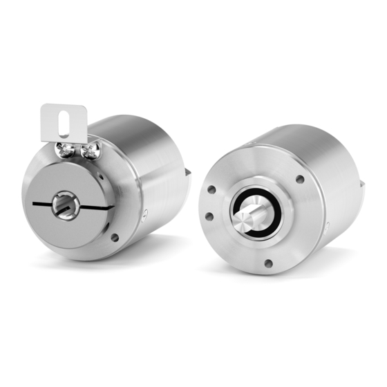
AM36
AMC36
• Miniature multiturn rotary encoder with optical scanning
• Resolution up to 19 x 12 bits
• Accuracy up to ± 0.01° (± 36 arc seconds) at 16-bit resolution
• SSI and BiSS C-mode interfaces
• High protection rate, IP67
• Ideal for robots, motors, electro-medical instruments, replacement
of resolvers
Suitable for the following models:
AM36xx/xxxxBG...
•
AM36xx/xxxxSC...
•
AMC36xx/xxxxBG...
•
AMC36xx/xxxxSC...
•
Lika Electronic
User's guide
•
Tel. +39 0445 806600
Table of Contents
•
info@lika.biz
10
11
14
18
21
35
•
www.lika.biz
8
Advertisement
Table of Contents

Related Manuals for Lika AM36 Series


Summary of Contents for Lika AM36 Series
-
Page 1: Table Of Contents
2 - Identification AM36xx/xxxxSC... • 3 - Mounting instructions AMC36xx/xxxxBG... • 4 - Electrical connections AMC36xx/xxxxSC... • 5 - SSI interface 6 - BiSS C-mode interface 7 - Default parameters list Lika Electronic • Tel. +39 0445 806600 • info@lika.biz • www.lika.biz... - Page 2 Tous droits réservés. This document and information contained herein are the property of Lika Electronic s.r.l. and shall not be reproduced in whole or in part without prior written approval of Lika Electronic s.r.l. Translation, reproduction and total or partial modification (photostat copies, film and microfilm included and any other means) are forbidden without written authorisation of Lika Electronic s.r.l.
-
Page 3: General Contents
General contents User's guide................................. 1 General contents..............................3 Subject Index............................... 5 Typographic and iconographic conventions....................6 Preliminary information............................ 7 1 - Safety summary............................8 1.1 Safety......................................8 1.2 Electrical safety..................................8 1.3 Mechanical safety..................................9 2 - Identification............................10 3 - Mounting instructions......................... 11 3.1 AM36 encumbrance sizes..............................11 3.2 AMC36 encumbrance sizes.............................11 3.3 Solid shaft encoders AM36 model..........................12... - Page 4 Save parameters and activate Preset......................25 Load and save default parameters........................25 Configuration................................26 Enable preset................................26 Output code................................27 Counting direction..............................27 Information per revolution..........................29 Number of revolutions............................29 Preset....................................30 Device type..................................32 N° of bits used for singleturn resolution....................32 N° of bits used for multiturn resolution....................32 Device ID..................................33 Manufacturer...
-
Page 5: Subject Index
Subject Index N° of bits used for singleturn resolution....32 Normal operational state..........25 Command................25 Number of revolutions..........29 Configuration..............26 Counting direction............27 CRC..................23p. Output code...............27 DATA..................23 Position.................22 Device ID................33 Preset..................30 Device type.................32 Profile ID................25 Enable preset..............26 Register address..............23 Error..................22 RW..................23 Information per revolution..........29 Save parameters and activate Preset......25 Save parameters on EEPROM........25 Serial number..............25... -
Page 6: Typographic And Iconographic Conventions
In this guide, to make it easier to understand and read the text the following typographic and iconographic conventions are used: parameters and objects both of Lika device and interface are coloured in GREEN; • alarms are coloured in RED;... -
Page 7: Preliminary Information
AMx36 is the smallest encoder with true geared multiturn and non contact optical scanning ever developed by Lika Electronic. So it does not require batteries. The core of the unit is the advanced optical sensing technology safely housed inside the industrial 36- mm case. -
Page 8: Safety Summary
• failure to comply with these precautions or with specific warnings elsewhere in this manual violates safety standards of design, manufacture, and intended use of the equipment; • Lika Electronic assumes no liability for the customer's failure to comply with these requirements. 1.2 Electrical safety •... -
Page 9: Mechanical Safety
AMx36 • SSI & BiSS C-mode on user’s side. The best solution to minimize the interference must be carried out by the user. 1.3 Mechanical safety • Install the device following strictly the information in the “3 - Mounting instructions” section on page 11; •... -
Page 10: Identification
Information is listed in the delivery document too. Please always quote the order code and the serial number when reaching Lika Electronic. For any information on the technical characteristics of the product refer to the technical catalogue. -
Page 11: Mounting Instructions
AMx36 • SSI & BiSS C-mode 3 - Mounting instructions WARNING Installation has to be carried out by qualified personnel only, with power supply disconnected and mechanical parts compulsorily in stop. 3.1 AM36 encumbrance sizes 3.2 AMC36 encumbrance sizes MAN AMx36 SSI_BiSS E 1.1.odt 3 - Mounting instructions 11 of 36... -
Page 12: Solid Shaft Encoders Am36 Model
AMx36 • SSI & BiSS C-mode 3.3 Solid shaft encoders AM36 model Mount the flexible coupling 1 on the encoder shaft; fix the encoder to the flange 2 by means of three M3 screws 3; secure the flange 2 either to the motor or to the mounting support; ... -
Page 13: Hollow Shaft Encoder Amc36 Model
AMx36 • SSI & BiSS C-mode 3.4 Hollow shaft encoder AMC36 model Mount the encoder on the motor shaft. Avoid forcing the encoder shaft; fasten the fixing plate 4 to the rear of the motor using an M3 cylindrical head screw 5;... -
Page 14: Electrical Connections
AMx36 • SSI & BiSS C-mode 4 - Electrical connections WARNING Power supply must be turned off before performing any electrical connection! If wires of unused signals come in contact, irreparable damage could be caused to the device. Thus they must be cut at different lengths and insulated singularly. -
Page 15: M8 Cable Specifications
AMx36 • SSI & BiSS C-mode 4.2 M8 cable specifications Model : LIKA HI-FLEX sensor cable type M8 Cross section : 2 x 0.22 mm + 6 x 0.14 mm (24/26 AWG) Jacket : Matt Polyurethane (TPU) halogen free, oil, hydrolysis,... -
Page 16: Counting Direction Input
AMx36 • SSI & BiSS C-mode 4.5 Counting direction input The Counting direction input allows to set whether the position value output by the encoder increases when the encoder shaft rotates clockwise (CW) or counterclockwise (CCW). The clockwise rotation is intended as shown in the Figure (CW and CCW rotations are viewed from shaft end). - Page 17 AMx36 • SSI & BiSS C-mode WARNING After having changed the counting direction you are required to set a new zero/Preset. MAN AMx36 SSI_BiSS E 1.1.odt 4 - Electrical connections 17 of 36...
-
Page 18: Ssi Interface
AMx36 • SSI & BiSS C-mode 5 - SSI interface Order codes: AMx36xx/4096BGx-... AMx36xx/4096GGx-... 5.1 SSI (Synchronous Serial Interface) Synchronous Serial SSI (the acronym for Interface) is a synchronous point-to-point serial interface engineered unidirectional data transmission between one Master and one Slave. Developed in the first eighties of the last century, it is based on the RS-422 serial standard. -
Page 19: Msb Left Aligned" Protocol
AMx36 • SSI & BiSS C-mode At each change of the clock signal and at each subsequent rising edge (2) one bit is clocked out at a time, up to LSB, so completing the data word transmission. The cycle ends at the last rising edge of the clock signal (3). This means that up to n + 1 rising edges of the clock signals are required for each data word transmission (where n is the bit resolution);... -
Page 20: Recommended Transmission Rates
AMx36 • SSI & BiSS C-mode Structure of the position information AMx3616/4096BGx... … AMx3616/4096GGx... AMx3619/4096BGx... … AMx3619/4096GGx... value … 5.3 Recommended transmission rates The SSI interface has a frequency of data transmission ranging between 100 kHz and 3 MHz. The CLOCK signal and the DATA signal comply with the “EIA standard RS-422”. The SSI clock frequency (baud rate) depends on the length of the cable and must comply with the technical information reported in the following table: Cable length... -
Page 21: Biss C-Mode Interface
6.1 XML file BiSS C-mode encoders are supplied with an XML file idbiss4C69.xml, it must be installed in your BiSS Master device. Download the XML file from Lika's web site. 6.2 Communication The BiSS C-mode protocol uses two types of data transmission protocols: Single Cycle Data (SCD): it is the main data transmission protocol. -
Page 22: Single Cycle Data Scd
AMx36 • SSI & BiSS C-mode 6.3 Single Cycle Data SCD SCD structure is different according to the resolution of the AMx36 model encoders. 6.3.1 SCD structure SCD data has a variable length according to the resolution of the encoder. It is nbitres+7 bit long where “nbitres”... -
Page 23: Crc
AMx36 • SSI & BiSS C-mode (6 bits) Correct transmission control (inverted output). Cyclic Redundancy Check is an error checking which is the result of a “Redundancy Checking” calculation performed on the message contents. This is intended to check whether transmission has been performed properly. -
Page 24: Crc
AMx36 • SSI & BiSS C-mode Data bit structure: … … … … Correct transmission control (inverted output). Cyclic Redundancy Check is an error checking which is the result of a “Redundancy Checking” calculation performed on the message contents. This is intended to check whether transmission has been performed properly. -
Page 25: Profile Id
AMx36 • SSI & BiSS C-mode - Address: the register address is expressed in hexadecimal notation. - Attribute: ro = read only rw = read and write wo = write only - Default parameter value is written in bold. Profile ID [42 - 43, ro] These registers contain the identification code of the used profile. -
Page 26: Configuration
Load and save default parameters: default parameters are set at the factory by Lika Electronic engineers to allow the operator to run the device for standard operation in a safe mode. As soon as the command is sent the default parameters are uploaded and activated. -
Page 27: Output Code
AMx36 • SSI & BiSS C-mode command (set “02” in the register 48 Command) to confirm the changes and activate the preset. Preset For detailed information refer to the parameter on page 30. Default = 0 (Enable) NOTE You can set the preset also by means of a signal from a PLC or a controller through the Zero setting/Preset input, see the “4.4 Zero setting/Preset input”... - Page 28 AMx36 • SSI & BiSS C-mode For any information on the electrical connection of the Counting direction input refer to the “4.5 Counting direction input“ section on page 16. WARNING After having set the new counting direction it is necessary to set also a new preset.
-
Page 29: Information Per Revolution
AMx36 • SSI & BiSS C-mode Information per revolution [4B … 4D, rw] These registers allow to set a custom number of information per revolution (singleturn resolution). You are allowed to enter any integer value which is a power of 2 (1, 2, 4, …, 2,048, 4,096, …) and is less than or equal to the number of physical information per revolution (= default value). -
Page 30: Preset
AMx36 • SSI & BiSS C-mode … 07 D0h = 2,000 revolutions … 08 00h = 2,048 revolutions … FF FFh = 65,535 revolutions WARNING Number of revolutions After having entered a new value next to the registers, the system zero sets the preset, thus you need to set it again, if required. WARNING If the number of revolutions you set is greater than 4,096 (10 00h), when the encoder is turned off you are forbidden from turning the shaft more than 2,047... - Page 31 AMx36 • SSI & BiSS C-mode The Preset value you are allowed to enter depends on the overall set resolution and must be less than or equal to (Information per revolution * Number of revolutions) - 1. Default = 00 00 00 00 00h Min.
-
Page 32: Device Type
AMx36 • SSI & BiSS C-mode Save parameters on EEPROM function in Command register Save parameters and activate Preset function in the Command register WARNING After having set the new counting direction or changed either the number of information per revolution or the number of revolutions it is necessary to set also a new preset. -
Page 33: Device Id
If the value in the register 7D is “31” hex, then the software version is “1”. Manufacturer ID [7E-7F, ro] These registers contain the Manufacturer ID. Identification name is expressed in hexadecimal ASCII code. Register ASCII Li = Lika Electronic 6.6 Application notes Data transmission: Parameter Value Clock Frequency Min 200 kHz, max 10 MHz... -
Page 34: Recommended Biss Input Circuit
AMx36 • SSI & BiSS C-mode 6.7 Recommended BiSS input circuit MAN AMx36 SSI_BiSS E 1.1.odt 6 - BiSS C-mode interface 34 of 36... -
Page 35: Default Parameters List
AMx36 • SSI & BiSS C-mode 7 - Default parameters list BiSS C-mode interface Parameters list Default value * Command Configuration Bit 0 not used Bit 1 not used Bit 2 Enable preset 0 = Enable Bit 3 not used Bit 4 not used Bit 5 Output code 1 = Binary... - Page 36 Ce dispositif doit être alimenté par un circuit de Classe 2 ou à très basse tension ou bien en appliquant une tension maxi de 30Vcc. Voir le code de commande pour la tension d'alimentation. Lika Electronic Via S. Lorenzo, 25 •...
Need help?
Do you have a question about the AM36 Series and is the answer not in the manual?
Questions and answers