Table of Contents
Advertisement
Quick Links
Smart encoders & actuators
SMS12
• Incremental linear encoder for 1-mm pole pitch tape
• Resolution 1 mm / 0.039"
• Measuring length up to 100 m / 328 ft
• IP67 protection rate
• 1Vpp sinusoidal outputs
• With external limit switches to mark off the travel
Suitable for the following models:
SMS12
•
Lika Electronic
User's guide
•
Tel. +39 0445 806600
Table of Contents
•
info@lika.biz
18
28
•
www.lika.biz
6
8
9
Advertisement
Table of Contents

Related Manuals for Lika SMS12


Summary of Contents for Lika SMS12
-
Page 1: Table Of Contents
User's guide Smart encoders & actuators SMS12 • Incremental linear encoder for 1-mm pole pitch tape • Resolution 1 mm / 0.039” • Measuring length up to 100 m / 328 ft • IP67 protection rate • 1Vpp sinusoidal outputs •... - Page 2 Tous droits réservés. This document and information contained herein are the property of Lika Electronic s.r.l. and shall not be reproduced in whole or in part without prior written approval of Lika Electronic s.r.l. Translation, reproduction and total or partial modification (photostat copies, film and microfilm included and any other means) are forbidden without written authorisation of Lika Electronic s.r.l.
-
Page 3: General Contents
General contents User's guide......................................1 General contents.....................................3 Typographic and iconographic conventions........................4 Preliminary information................................5 1 Safety summary............................. 6 1.1 Safety.....................................6 1.2 Electrical safety.................................6 1.3 Mechanical safety..............................7 2 Identification............................8 3 Mechanical installation........................9 3.1 Overall dimensions..............................9 3.2 Sensor and scale / ring combination......................10 3.3 Magnetic tape.................................10 3.4 Magnetic rings................................10 3.5 Mounting the sensor with magnetic tape....................11... -
Page 4: Typographic And Iconographic Conventions
Typographic and iconographic conventions In this guide, to make it easier to understand and read the text the following typographic and iconographic conventions are used: parameters are coloured in GREEN; • alarms are coloured in RED; • states are coloured in FUCSIA. •... -
Page 5: Preliminary Information
SMS12 incremental linear encoder. SMS12 linear encoder is designed to measure linear or angular displacements on industrial machines and automation systems. The measurement system includes a magnetic tape / magnetic ring and a magnetic sensor. -
Page 6: Safety Summary
• elsewhere in this manual violates safety standards of design, manufacture, and intended use of the equipment; Lika Electronic assumes no liability for the customer's failure to comply • with these requirements. 1.2 Electrical safety Turn OFF the power supply before connecting the device;... -
Page 7: Mechanical Safety
(as for instance brushes, scrapers, jets of compressed air, etc.) are in place in order to prevent the sensor and the magnetic tape from jamming. MAN SMS12 E 1.1 Safety summary 7 of 32... -
Page 8: Identification
Information is listed in the delivery document too. Please always quote the order code and the serial number when reaching Lika Electronic for purchasing spare parts or needing assistance. For any information on the technical characteristics of the product refer to the technical catalogue. -
Page 9: Mechanical Installation
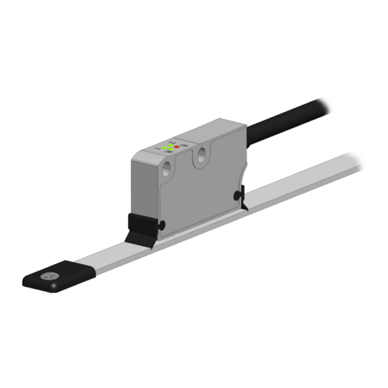
3.1 Overall dimensions (values are expressed in mm) Reference sensor “R” / “T” (page D Optional cleaning wipers (page 17) Limit switch sensors “LS” (page E Diagnostic LEDs (page 25) C Incremental sensor MAN SMS12 E 1.1 Mechanical installation 9 of 32... -
Page 10: Sensor And Scale / Ring Combination
Furthermore it can be installed also on round surfaces and magnetic rings. As stated, the sensor model must be compulsorily paired with its specific type of magnetic ring (see the “3.2 Sensor and scale / ring combination” section). MAN SMS12 E 1.1 Mechanical installation 10 of 32... -
Page 11: Mounting The Sensor With Magnetic Tape
Distance D between Distance D between Sensor sensor and MT tape sensor and cover strip 0.1 mm 0.5 mm 0.1 mm 0.3 mm SMS12 0.004” 0.019” 0.004” 0.012” MAN SMS12 E 1.1 Mechanical installation 11 of 32... - Page 12 Figure 2 all along the whole measuring length. Figure 2 - Encoder / tape mounting tolerances MAN SMS12 E 1.1 Mechanical installation 12 of 32...
-
Page 13: Mounting The Sensor With "R" / "T" Reference
Figure 3 - External Reference D1: gap to be compliant with between the sensor and the LKM-1309/1 external magnet. D2: distance from the centre of fixing hole to the edge of the Reference Mark. MAN SMS12 E 1.1 Mechanical installation 13 of 32... -
Page 14: Mounting The Sensor With Ls1 And Ls2 Limit Switches
0.287” 3.7 Mounting the sensor with LS1 and LS2 limit switches SMS12 linear encoder integrates two sensors designed to detect external limit switches (code LKM-1309/LS). They allow to detect the ends in the travel. External references LS1 and LS2 must be installed at either/both ends of the sensor's travel on the side shown in the Figure respecting the indicated tolerances. -
Page 15: Measuring Length
(as for instance brushes, scrapers, jets of compressed air, etc.) are in place in order to prevent the sensor and the magnetic scale from jamming. MAN SMS12 E 1.1 Mechanical installation 15 of 32... - Page 16 To learn about the mounting tolerances refer to the tables below as well as to Figure 5 and Figure 6. Figure 6 - Sensor / ring mounting gap Sensor Distance DR between sensor and MRI ring 0.1 mm 0.5 mm SMS12 0.004” 0.019” MAN SMS12 E 1.1 Mechanical installation 16 of 32...
-
Page 17: Standard Counting Direction
This encoder can be optionally provided with rubber cleaning wipers to be mounted on the sensing head (order code KIT WIPERS). They are designed for debris removal from the magnetic tape surface in order to ensure a clear path of motion. MAN SMS12 E 1.1 Mechanical installation 17 of 32... -
Page 18: Electrical Connection
LS1 / LS2 limit switch signals (see the “4.9 LS1 and LS2 limit switches” section on page 23). NOTE All sensors can provide inverted signals. A = A signal; /A = inverted A signal (or complementary signal). MAN SMS12 E 1.1 Electrical connection 18 of 32... -
Page 19: M10 Cable Specifications
SMS12 All Lika's magnetic sensors can provide AB0, /AB0 output signals. You are advised to always connect the inverted signals if the receiving device will accept them. Otherwise each output should be insulated singularly. 4.2 M10 cable specifications Model : LIKA HI-FLEX sensor cable type M10 Cross section : 2 x 0.22 mm... -
Page 20: Connection Of The Shield
The best solution to minimize the interference must be carried out by the user. You are advised to provide the ground connection as close as possible to the encoder. MAN SMS12 E 1.1 Electrical connection 20 of 32... -
Page 21: Ab0, /Ab0 Output Channels
Figure 6 in a rotary application (see the “4.5 AB0, /AB0 output channels” section on page 21). Thus the counter in the subsequent electronics will get a count up. It cannot be changed. MAN SMS12 E 1.1 Electrical connection 21 of 32... -
Page 22: Reference "R" / "T
The typical repeatability of the signal is 1% of the period length. EXAMPLE SMS12, 1 mm pole pitch: 1000 µm / 100 = 10 µm The Reference signal has a duration of 70 ±10 electrical degrees. The accuracy and the duration of the Reference pulse may vary depending on the alignment of the Reference magnet and the magnetic scale, see the Figure 8. -
Page 23: Voltage Signals
Av = R2 / R1 4.9 LS1 and LS2 limit switches SMS12 linear encoder integrates two sensors designed to detect external limit switches (code LKM-1309/LS). They allow to detect the ends in the travel. External references LS1 and LS2 must be installed at either/both ends of the sensor's travel on the side shown in the Figure and according to the indicated tolerances. - Page 24 SMS12 determine whether the encoder is at an end-of-travel and in which direction to drive the axis. Figure 9 - LS limit switches MAN SMS12 E 1.1 Electrical connection 24 of 32...
-
Page 25: Diagnostic Leds (Figure 10)
Figure 10 - Diagnostic LEDs and optional cleaning wipers GREEN Description (Limit Switch LS1) It lights up when the LS1 sensor detects the Green external LKM-1309/LS1 limit switch. It is MAN SMS12 E 1.1 Electrical connection 25 of 32... - Page 26 (Figure 8). External Reference not detected. NOTE If an error occurs switch off and then on again the encoder and check whether the problem is cleared up and the LED turns off. MAN SMS12 E 1.1 Electrical connection 26 of 32...
-
Page 27: Recommended Circuit
SMS12 4.11 Recommended circuit MAN SMS12 E 1.1 Electrical connection 27 of 32... -
Page 28: Maintenance And Troubleshooting
A section of the magnetic scale / ring has been damaged mechanically • or magnetically along the measuring length. The measuring error is caused by torsion of the machine structure. • Check parallelism and symmetry of machine movement. MAN SMS12 E 1.1 Maintenance and troubleshooting 28 of 32... - Page 29 SMS12 NOTE If an error occurs switch off and then on again the encoder and check whether the problem is cleared up and the LED turns off. MAN SMS12 E 1.1 Maintenance and troubleshooting 29 of 32...
- Page 30 This page intentionally left blank...
- Page 31 This page intentionally left blank...
- Page 32 Document release Release date Description Interface 16.06.2016 First issue 10.07.2018 New mechanical version Lika Electronic Via S. Lorenzo, 25 • 36010 Carrè (VI) • Italy Tel. +39 0445 806600 Fax +39 0445 806699 info@lika.biz • www.lika.biz...
Need help?
Do you have a question about the SMS12 and is the answer not in the manual?
Questions and answers