
Related Manuals for Renishaw RMI-Q


Summary of Contents for Renishaw RMI-Q
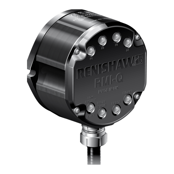
- Page 1 Installation guide H-5687-8504-01-A (BETA SITE ONLY) RMI-Q radio machine interface...
- Page 2 © 2012 Renishaw plc. All rights reserved. This document may not be copied or reproduced in whole or in part, or transferred to any other media or language, by any means, without the prior written permission of Renishaw plc. The publication of material within this document does not imply freedom from the patent rights of Renishaw plc.
-
Page 3: Table Of Contents
RMI-Q visual diagnostics ........ - Page 4 To partner the RMP with the RMI-Q ......... . . 3.3 To partner up to four RMPs with the RMI-Q without ReniKey ..... . . 3.4 Partnering RMPs using ReniKey (Recommended) .
-
Page 5: Before You Begin
RENISHAW HAS MADE CONSIDERABLE Unless otherwise specifically agreed in writing EFFORTS TO ENSURE THE CONTENT OF THIS between you and Renishaw, if you purchased the DOCUMENT IS CORRECT AT THE DATE OF equipment from a Renishaw company, the warranty PUBLICATION BUT MAKES NO WARRANTIES provisions contained in Renishaw’s CONDITIONS... -
Page 6: Rmp Probe Family
RMP probe family Patents The RMP family of probes currently consists of the Features of the RMI-Q (and features of similar RMP40, RMP40M, RLP40, RMP60, RMP60M and products) are the subject of one or more of the RMP600. The RTS radio tool setter also forms part following patents and/or patent applications: of Renishaw's family of radio transmission probes. -
Page 7: Ec Declaration Of Conformity
47 CFR Section 15.19 The user is cautioned that any changes or modifications not expressly approved by Renishaw PLC hereby declares that the RMI-Q is in compliance with the essential requirements and Renishaw plc, or authorised representative could void the user’s authority to operate the equipment. -
Page 8: Radio Approval
RMI-Q installation guide Radio approval Radio approvals Europe: Radio equipment - Canadian warning USA: statements Canada: Japan: English China: Under Industry Canada regulations, this radio transmitter may only operate using an antenna of a type and maximum (or lesser) gain approved for the transmitter by Industry Canada. -
Page 9: Safety
Information to the equipment installer Safety All Renishaw equipment is designed to comply Information to the user with the relevant EU and FCC regulatory requirements. It is the responsibility of the In all applications involving the use of machine equipment installer to ensure that the following tools or CMMs, eye protection is recommended. - Page 10 RMI-Q installation guide This page left intentionally blank...
-
Page 11: Rmi-Q Basics
RMI-Q basics Introduction Optimum communication performance between the RMI-Q and the RMP is achieved when the CNC machine tools which are using Renishaw RMI-Q is aligned towards the RMP in operation. spindle probes with radio signal transmission Other alignments are permissible with negligible for workpiece inspection, or tool setters with reduction in communication performance. -
Page 12: Rmi-Q Visual Diagnostics
RMI-Q installation guide RMI-Q visual diagnostics A visual indication of system status is provided by LEDs. Status is continuously updated and indication is provided for: P1, P2, P3, P4 SYSTEM STATUS; • LOW BATTERY/START; • PROBE STATUS; • SIGNAL CONDITION;... -
Page 13: P1, P2, P3, P4 System Status Leds
NOTES: LOW BATTERY / START LED The 'PROBE STATUS' LED is always illuminated when power is present at the RMI-Q (as the Battery is OK and no M code RMI-Q does not incorporate a separate ‘power start/stop in progress. -
Page 14: Rmi-Q Inputs
RMI-Q installation guide RMI-Q inputs Output voltages Sourcing = 4.2 V min at 10 mA. • Machine start inputs (P1, P2, P3, P4): = 2.2 V min at 50 mA. 'Machine start' inputs are configurable as a level Sinking = 0.4 V max at 10 mA. - Page 15 (green/yellow), or the red wire and screen wire (green/yellow), or the red and black wires (power supply), as this could result in permanent damage to the RMI-Q and/or the customer power supply. The use of in-line fuses at the machine cabinet end is recommended to provide protection for the RMI and cable.
-
Page 16: Rmi-Q Output Waveforms
RMI-Q installation guide RMI-Q output waveforms PROBE RMI-Q Power SSR/driven Seated Triggered Seated output Probe Error Probe Probe Probe switch e.g. Error switch trigger reseat low signal clear battery SSR open Probe status 1 (level) Normally open SSR closed SSR open... -
Page 17: Rmi-Q Seated Start Option
RMI-Q seated start option PROBE Triggered Power Seated Error Probe clear switch RMI-Q SSR/driven Error Probe output Probe e.g. switch Probe trigger battery low signal reseat Probe status 1 SSR open (level) Normally open SSR closed Probe status 1 SSR open... -
Page 18: Switches Sw1 And Sw2
RMI-Q installation guide Switches SW1 and SW2 NOTE: To gain access to the switches, remove the front cover (see Section 4, 'Maintenance'). Switch SW1 output configuration PROBE STATUS 1 battery Error Pulsed Abbreviations are as follows: • N/O = Normally Open •... -
Page 19: Switch Sw2 Output Configuration
Switch SW2 output configuration PROBE STATUS 2a/2b Dedicated Seated 0.5 s Normally Pulsed Level start start on turn on high Factory settings are shown. Level Normally Pulsed Common Seated Standard start start off turn on Dedicated start (level mode) NOTES : Level start mode is not compatible with RMPs In dedicated start, a machine start input is configured for radio M code on/time out off. - Page 20 Level start mode is not compatible with RMPs configured for radio M code on/time out off. Seated start on When seated start on is selected, the RMI-Q will not drop the error line until the RMP has become seated. This provides compatibility with controllers that regard the RMP to be in error if it is started in a triggered condition.
-
Page 21: Remote External Audible Output
The audible indicator must comply with the output transistor specification. i.e. up to 50 mA. 2.11 up to 30 V. Wiring configurations are shown below. RMI-Q Option 1. Turquoise SSR output Turquoise / Black 0 V Black –ve RMI-Q Option 2. -
Page 22: Rmi-Q Dimensions
RMI-Q installation guide RMI-Q dimensions 97 (3.82) 44 (1.73) 46 (1.81) 46 (1.81) 2.12 17.5 (0.69) 4 holes 45° M5 x 13 deep on 80 P.C.D.. Slot to suit M5 x 16 bolts supplied (two places) NOTE: When using rear exit cable, provide a Ø25 mm (Ø1.0 in) hole in the... -
Page 23: Rmi-Q Specification
2.13 Depth 44 mm (1.73 in) Weight In box 2,065 g (72.84 oz) RMI-Q including 15 m 1,625 g (57.32 oz) (49.2 ft) of cable Transmission type Frequency hopping spread spectrum (FHSS) radio. 2.400 - 2.4835 GHz 2400 - 2483.5 MHz Transmission range Up to 15 m (49.2 ft) - Page 24 RMI-Q installation guide 2.14 This page left intentionally blank...
-
Page 25: System Installation
System installation Mounting bracket (optional) Dimensions given in mm (in) NOTES: Install RMI-Q with cable exiting from lower side for good coolant run off. Mounting bracket cannot be used with an RMI-Q in rear exit configuration. (0.98) (0.98) 3 grip protrusions 3 holes Ø6.4 (0.25) -
Page 26: Wiring Diagram (With Output Groupings Shown)
Green Machine ground (star point) NOTE: A switch can be added on installation to aid with powering up the RMI-Q when partnering. CAUTION: The power supply 0 V should be terminated at the machine ground (star point). A negative supply can be used when wired appropriately. -
Page 27: Rmp - Rmi-Q Partnership
Trigger Logic™ is a method that allows the user to view and select all available mode settings Power on the RMI-Q or apply one of the in order to customise a probe to suit a specific ReniKey commands. Please refer to the application. -
Page 28: To Partner Up To Four Rmps With The Rmi-Q Without Renikey
Probe 2 Partnering with dedicated start (Level mode) Probe 3 Probe 4 If the RMI-Q is powered with all start inputs held low, the RMI-Q will complete its start up Level mode procedure and partner the RMP as Probe 1. -
Page 29: Partnering Rmps Using Renikey (Recommended)
Alternatively, refer to www.renishaw. com. ReniKey can also be used to clear all probe numbers at the same time. If the cleared RMP is to be used again with the RMI-Q, it must be re-partnered. Changing RMP position If, during partnering with all procedures, the... -
Page 30: Rmi-Q Cable
A ferrule should be crimped onto each cable wire for a more positive connection at the terminal box. Standard cable variants The RMI-Q standard cables are 8 m (24.6 ft) and 15 m (49.2 ft) long. Longer cables are available, please see Section 6, 'Parts list'. -
Page 31: Screw Torque Values
(1.47 lbf. ft) T10 tamperproof 1.0 Nm (0.74 lbf.ft) 4 mm AF 5.1 Nm (3.76 lbf. ft) HOLD 22.0 mm AF (7/8 AF) Conduit adaptor to RMI-Q body 7 Nm (5.16 lbf.ft) Rear exit plug (not shown) 5 Nm (3.69 lbf.ft) - Page 32 RMI-Q installation guide This page left intentionally blank...
-
Page 33: Maintenance
Conduit Antenna contacts Cable SAFETY The main power supply to the machine must be switched off before working on the RMI-Q. WARNING Only qualified persons should dismantle this equipment. Faulty workmanship will invalidate the warranty. KEEP CLEAN Liquids and solid particles must NOT be allowed to enter the RMI-Q body. -
Page 34: Replacing The Rmi-Q Cover
Remove the three crosshead screws Ensure that the O-ring seating on the retaining the PCB. Carefully remove the RMI-Q body is clean, and that there are no PCB and disconnect the cable connection to scratch marks which could prevent complete the PCB. -
Page 35: Fault Finding
RMP is not compatible with 0.5 Change turn on time to 1 second. second turn on. All RMI-Q LEDs flashing. Wiring fault. Check wiring. Output overcurrent. Check wiring, turn power to RMI-Q off and on again to reset. - Page 36 RMI-Q installation guide Symptom Cause Action RMI-Q low battery LED Low RMP batteries. Change RMP batteries soon. lit. Reduced range. Local radio interference. Identify and remove. RMP has been enclosed / Review installation. shielded by metal. RMI-Q System Status RMP is not compatible for 0.5...
-
Page 37: Parts List
Software features H-2000-2289 Data sheet: Probe software for machine tools – illustrated features. Software list H-2000-2298 Data sheet: Probe software for machine tools – list of programs. NOTE: The serial number of each RMI-Q is found on the top of the housing. - Page 38 Renishaw plc +44 (0)1453 524524 +44 (0)1453 524901 New Mills, Wotton-under-Edge, uk@renishaw.com Gloucestershire, GL12 8JR United Kingdom www.renishaw.com For worldwide contact details, please visit our main website at www.renishaw.com/contact *H-5687-8504-01* © 2012 Renishaw plc Issued (BETA SITE ONLY) Part no. H-5687-8504-01-A...
Need help?
Do you have a question about the RMI-Q and is the answer not in the manual?
Questions and answers