Table of Contents
Advertisement
Advertisement
Table of Contents

Subscribe to Our Youtube Channel
Related Manuals for Renishaw RMI


Summary of Contents for Renishaw RMI
- Page 1 Installation and user’s guide H-2000-5220-05-A RMI - radio machine interface...
- Page 2 Trademarks RENISHAW® and the probe emblem used in the RENISHAW logo are registered trademarks of Renishaw plc in the UK and other countries. apply innovation and Trigger Logic are trademarks of Renishaw plc. All brand names and product names used in...
-
Page 3: Table Of Contents
Remote external audible output ....19 Safety ............... 3 RMI cable ............20 Installation and user’s guide ......4 RMI cable sealing .......... 21 RMI ..............5 Fitting flexible conduit ........21 Mounting bracket ..........6 RMI cover ............22 RMI visual diagnostics ........ -
Page 4: Ec Declaration Of Conformity
Emissions to class A - (non-domestic) limits. and that it complies with the requirements of directive (as amended): 89/336/EEC Electromagnetic compatibility The above information is summarised from the full EC declaration of conformity. A copy is available from Renishaw on request. Radio approvals Japan: 004NYCA0042 Brazil:... -
Page 5: Fcc Declaration (Usa)
Under certain circumstances the probe signal The user is cautioned that any changes or may falsely indicate a probe seated condition. modifications not expressly approved by Renishaw Do not rely on probe signals to stop the plc, or authorised representative could void the machine’s movement. -
Page 6: Installation And User's Guide
RMI with care. operation over 5 °C to 50 °C (41 °F to 122 °F) ambient temperature range. Do not apply metallic labels to the front of the RMI. Sealing Changes to equipment The unit is fully sealed to IPX8. -
Page 7: Rmi
Renishaw PSU3 power supply unit. Power supply Input voltage ripple The RMI can draw its supply from the CNC The input voltage ripple shall not cause the machine 12 V to 30 V d.c. supply and presents voltage to fall below 12 V, or rise above 30 V. -
Page 8: Mounting Bracket
NOTE: Install RMI with cable exiting from 45° 45 (1.77) lower side for good coolant run off. 90 (3.54) Mounting bracket cannot be used (0.08) with an RMI in rear exit configuration. Paired holes permit RMI mounting in alternative orientation. -
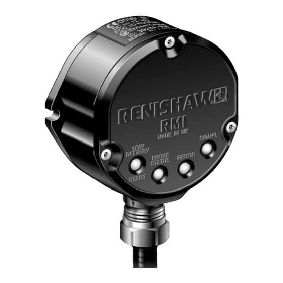
Page 9: Rmi Visual Diagnostics
RMI visual diagnostics RMI visual diagnostics A visual indication of system status is provided by LEDs. Status is continuously updated and indication is provided for START, LOW BATTERY, PROBE STATUS, ERROR, SIGNAL STRENGTH LED LIGHT SIGNALS 1. LOW BATTERY / START Battery is low. - Page 10 Yellow Good communications. other LEDs will be off. Poor communications, 3. When the RMI is powered it will enter the radio link may fail. acquire partner mode which will be indicated by the flashing green signal LED (no change No signal detected.
-
Page 11: Rmi Outputs
RMI outputs RMI outputs There are five outputs: Probe status 2a (5 V isolated driven skip): Probe status 1 (SSR) Load current = 50 mA max. Probe status 2a (5 V isolated driven skip) Output voltages Probe status 2b (driven at power supply Sourcing = 4.2 V min at 10 mA. - Page 12 The Low Battery, Probe Status, and Error LEDs will start flashing red when an output overload has occurred. All outputs will be switched off. If this occurs, turn off the power supply and remove the source of the problem. Turning on the power supply will reset the RMI.
- Page 13 (green/yellow), or the red and black wires (power supply), as this could result in permanent damage to the RMI and/or the customer power supply. The use of in-line fuses at the machine cabinet end is recommended to provide protection for the RMI and cable.
-
Page 14: Rmi Output Waveforms
RMI output waveforms RMI output waveforms (outputs can be inverted by switches - see section ‘Switches SW1, SW2 and Start Input’) PROBE Seated Probe Seated Triggered Error Probe switch e.g. Error switch SSR / driven Probe Probe battery low signal... - Page 15 RMI output waveforms PROBE Seated Probe Seated Triggered Error Probe switch Probe Probe e.g. Error switch SSR / driven reseat trigger low signal clear battery outputs Power SSR open LOW BATTERY SSR closed Normally open PROBE STATUS Output high 2a/2b...
-
Page 16: Switches Sw1, Sw2 And Start Input
Switches SW1, SW2 and start input Switches SW1 and SW2 Switch SW1 output configuration Pulsed To gain access to the switches, remove the RMI cover. Level SWITCH SW1 output configuration CAUTION: Factory settings shown are for: Exercise caution when using error SSR in... - Page 17 Switches SW1, SW2 and start input Switch SW2 output Start input configuration Machine start Factory settings shown are for: A-4113-0050 ‘Machine start’ is configurable as a level or pulsed signal. 10 - 30 V (2.4 mA at 24 V) Level When input is active, probe is switched on Pulsed...
-
Page 18: Wiring Diagram
(with the output groupings shown) Turquoise Probe status 1 Turquoise/black (SSR) Note Violet Switch can be added Low battery Violet/black on installation to aid (SSR) with RMI power up Green Error for partnering. Green/black (SSR) White Brown Machine start input –ve Yellow Driver... -
Page 19: Rmp60-Rmi Partnership
Reviewing of choices can be made by battery 6. Power on RMI. insertion alone. See RMP60 user’s guide for 7. Watch the RMI signal LED; after a couple full details of reviewing probe settings. of seconds the LED will repeatedly flash on and off green. - Page 20 Note When the RMP60 and RMI become partners the RMI records the RMP60 serial number. It is not possible for an RMI to be partnered with more than one standard RMP60. It is possible for an RMP60 to be partnered with more than one RMI, but the system will not function correctly.
-
Page 21: Remote External Audible Output
Remote external audible output Remote external audible output Any output (set to pulsed) can be utilised to The audible indicator must comply with the output transistor specification. operate an external remote audible indicator. i.e. up to 50 mA. Wiring configurations are shown below. up to 30 V. -
Page 22: Rmi Cable
RMI cable Cable termination Standard cable A ferrule should be crimped onto each cable The RMI standard cable is 15 m (49.2 ft) long, core for more positive connection at the terminal longer cables are available - see Parts list. box. -
Page 23: Rmi Cable Sealing
RMI cable sealing and fitting flexible conduit RMI cable sealing Fitting flexible conduit Coolant and dirt are prevented from entering the RMI by the cable sealing gland. The cable can be protected against physical damage by fitting flexible conduit if required. Recommended flexible conduit is Anamet Sealtite HFX (5/16 in) polyurethane. -
Page 24: Rmi Cover
For torque settings see Screw torque values. 2. Ensure that the 'O' ring seating on the RMI body is clean, and there are no scratch marks which could prevent complete Removing the RMI cover sealing. - Page 25 RMI cover RMI body Cable clamp RMI cover Conduit adaptor Conduit Cable Antenna contacts CAUTION: KEEP RMI CLEAN No liquids or solid particles must be allowed to enter the RMI body. DO NOT allow the antenna contacts to be contaminated.
-
Page 26: Side Exit To Rear Exit Cable Conversion
Fit rubber grommet and rear exit plug to side exit hole and tighten. Fit cable assembly using cable clamp at 3 o’clock position. Connect PCB to cable connector. Insert PCB and retain with 3 cross head screws. 10. Fit the RMI cover (page 22). -
Page 27: Screw Torque Values
T10 tamper proof 1,4 Nm (1.47 lbf.ft) (1.03 lbf.ft) 4 mm AF 5,1 Nm (3.76 lbf.ft) HOLD 22,2 mm AF (7/8 AF) Conduit adaptor to RMI body 10 Nm (7.38 lbf.ft) Rear exit plug (not shown) 10 Nm (7.38 lbf.ft) -
Page 28: Fault Finding
Fault-finding Fault finding - If in doubt, consult your probe supplier. Symptom Cause Action No LEDs lit on RMI No power to RMI Check wiring RMI status LEDs do not Radio link failure - RMP60 Check position of RMI, correspond to RMP60... - Page 29 (RMP60 User’s guide) All RMI LEDs flashing Wiring fault Check wiring Output over-current Check wiring, turn power to RMI off and on again to reset RMI low battery LED lit Low RMP60 batteries Change RMP60 batteries soon Reduced range Local radio interference...
-
Page 30: Parts List
T10 tamperproof key, 4 mm hex key, 14 x ferrules, 4 x M5 screw, 2 x M5 nut, 4 x M5 washer, O ring (Ø34,5 x 3 mm) The serial number of each RMI is found on the top of the housing. - Page 31 Renishaw plc +44 (0)1453 524524 New Mills, Wotton-under-Edge, +44 (0)1453 524901 Gloucestershire, GL12 8JR uk@renishaw.com United Kingdom www.renishaw.com For worldwide contact details, please visit our main web site at www.renishaw.com/contact *H-2000-5220-05*...
Need help?
Do you have a question about the RMI and is the answer not in the manual?
Questions and answers