Table of Contents
Advertisement
Quick Links
Advertisement
Table of Contents

Related Manuals for Renishaw RMI


Summary of Contents for Renishaw RMI
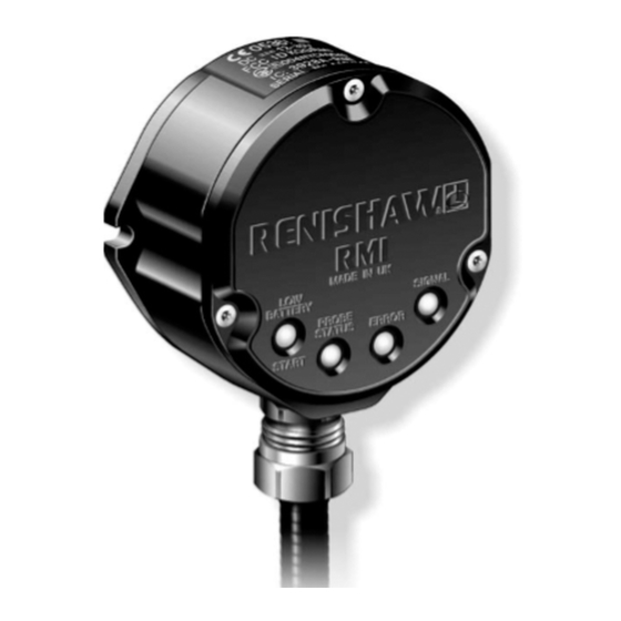
- Page 1 Installation and user’s guide H-2000-5220-01-A RMI - radio machine interface...
- Page 2 Disclaimer © 2003 Renishaw. All rights reserved. Considerable effort has been made to ensure Renishaw® is a registered trademark of that the contents of this document are free from Renishaw plc. inaccuracies and omissions. However, Renishaw makes no warranties with respect to the...
- Page 3 Emissions to class A (non-domestic) limits. and that it complies with the requirements of directive (as amended): - 89/336/EEC Electromagnetic compatibility The above information is summarised from the full EC declaration of conformity. A copy is available from Renishaw on request.
- Page 4 –10° to 70° C (14° to 158° F) and operation RMI with care. over 5° to 60° C (41° to 140° F) ambient temperature range. Do not apply metallic labels to the front of the RMI. Sealing Changes to equipment The unit is fully sealed to IPX8.
-
Page 5: Table Of Contents
Remote external audible output ....19 RMI outputs ............. 8 Mounting bracket .......... 20 RMI output waveforms ........10 Removing and refitting the RMI cover ..21 Wiring diagram ..........12 Removing and refitting PCB ......23 Switches SW1, SW2 and start input ..... 13 Side to rear exit conversion ...... -
Page 6: Rmi
Input voltage ripple The input voltage ripple shall not cause the The RMI can draw its supply from the CNC voltage to fall below 12 V, or rise above 30 V. machine 12 V to 30 V d.c. supply and presents a... -
Page 7: Operating Envelope
Operating envelope Operating envelope RMP60 probe + RMI Range metres (feet) RMP60 and RMI must be within each others OPERATING AND SWITCH ON/OFF operating envelope shown. 75° 15 (49) 60° 90° 75° 75° 10 (33) 60° 60° 45° 45° 45°... -
Page 8: Rmi Visual Diagnostics
RMI visual diagnostics RMI visual diagnostics A visual indication of system status is provided by LED's. Status is continuously updated and indication is provided for START, LOW BATTERY, PROBE STATUS, ERROR, SIGNAL STRENGTH LED LIGHT SIGNALS 1. LOW BATTERY Battery is low. - Page 9 Yellow Medium signal strength. LEDs will be off. Low signal strength, radio 3. When the RMI is powered it will enter the link may fail. acquire partner mode which will be indicated by the flashing green signal LED. No signal detected.
-
Page 10: Rmi Outputs
RMI outputs RMI outputs SSR outputs: There are four outputs: Probe status 1 (SSR) DC ‘ON’ resistance 60 ohms max. Up to 50 mA protected. Probe status 2a (driven skip 5 V isolated) Probe status 2b (driven at power supply Switching time = Less than 10 µs (low to high) - Page 11 (grey/black), or the red and black wires (power supply), as this could result in permanent damage to the RMI and/or the customer power supply. The use of in-line fuses at the machine cabinet end is recommended to provide protection...
-
Page 12: Rmi Output Waveforms
RMI output waveforms PROBE OUTPUTS Seated Probe Seated Triggered Error Probe SSR / driven switch Probe Probe e.g. Error switch output battery trigger reseat low signal clear (switch Power position) PROBE STATUS 1 (LEVEL) open closed Normally closed PROBE STATUS 1... - Page 13 RMI output waveforms RMI output waveforms (outputs can be inverted by switches) PROBE Seated Probe Seated Triggered Error Probe switch Probe e.g. Error switch Probe Power OUTPUTS reseat low signal clear battery trigger ERROR open closed Normally closed BATTERY open...
-
Page 14: Wiring Diagram
Wiring diagram Wiring diagram (with the output groupings shown) Turquoise Probe status pair (SSR) Turquoise / black Violet Low battery pair (SSR) Violet / black Green Error pair (SSR) Green / black Orange Skip drive at power supply voltage Yellow High speed skip drive (5 V) Grey High speed skip return (0 V) -
Page 15: Switches Sw1, Sw2 And Start Input
PROBE PROBE LOW BAT N.O. STATUS 1 N.O. STATUS 1 N.O. Pulsed To gain access to the switches, remove the RMI cover - see page 20 PROBE PROBE STATUS 1 ERROR STATUS 1 LOW BAT Start input Level N.C. N.C. - Page 16 Switches SW1, SW2, and start input Switch SW2 output configuration PROBE PROBE HEIDENHAIN STATUS 2 STATUS 2 COMPATIBLE Pulsed Trigger low NOT USED PROBE HEIDENHAIN NOT USED PROBE STATUS 2 COMPATIBLE STATUS 1 Level Trigger high NOTE: When in Heidenhain compatible on mode M code turn off cannot be used...
-
Page 17: Rmi Cable
Cable termination Standard cable A ferrule should be crimped onto each cable The RMI standard cable is 15 m (49.2 ft) long, core for more positive connection at the terminal longer cables are avaible (see page 25). box. To fit a ferrule, insert the prepared core into... -
Page 18: Rmi Cable Sealing And Fitting Flexible Conduit
3. Fit conduit to adaptor A and tighten nut B. CAUTION: Failure to adequately protect the cable can result in system failure due to either cable damage or coolant ingress through cores into the RMI. Failure due to inadequate cable protection will invalidate the warranty. -
Page 19: Rmi-Rmp Partnership
RMI records the RMP serial number. It is not window. possible for an RMI to be partners with more than one RMP. 3. Power on the RMI. It is possible for an RMP to be partners with more than one RMI, but the system will not 4. -
Page 20: Installation With Inspection And Tool Setting Probe
Installation with inspection and tool setting probe Installation with inspection and tooletting probe On machines where the RMI is to be integrated with a tool setting probe input, and only one probe input is provided on the control, an M code can be utilised... -
Page 21: Remote External Audible Output
Remote external audible autoput Remote external audible output The audible indicator must comply with the The pulsed output can be utilized to operate output transistor specification an external remote audible indicator. i.e. 50 mA peak Wiring configurations are shown below. 30 V peak Pulse duration is 40 ms ±1 ms. -
Page 22: Mounting Bracket
Install RMI with cable exiting from 6 holes lower side for good coolant run off. Ø5.3 (0.20) Mounting bracket cannot be used with an RMI in rear exit configuration. 45° 45 (1.77) Do not apply any metallic label to 90 (3.54) the front cover, as this will shield (0.08) -
Page 23: Removing And Refitting The Rmi Cover
For torque settings please could prevent sealing. see page 24. 2. Ensure that the 'O' ring seating on the RMI body is clean, and there are no scratch Removing the RMI cover marks which could prevent complete sealing. - Page 24 Removing and refitting the RMI cover RMI body Cable clamp RMI cover Conduit adaptor Conduit Cable CAUTION: KEEP RMI CLEAN No liquids or solid particles must be allowed to enter the RMI body. DO NOT allow the antenna contacts to be contaminated.
-
Page 25: Removing And Refitting Pcb
PCB cable conversion 1. Remove RMI cover (page 20) To remove PCB 1. Remove the RMI cover (page 20). 2. Remove PCB. 2. Remove 3 crosshead screws retaining 3. Unscrew cable clamp (2 x crosshead PCB. Carefully remove PCB and screws). -
Page 26: Screw Torque Values
Screw torque values Screw torque values Nm (lbf.ft). Conduit adaptor to RMI body 10 Nm (7.38 lbf.ft) 3 mm AF Rear exit plug (not shown) 2 Nm 10 Nm (7.38 lbf.ft) (1.47 lbf.ft) 2 mm 1.4 Nm 4 mm AF (1.03 lbf.ft) -
Page 27: Parts List
2mm hex key, 4 mm hex key, 14 x ferrules, 4 x M5 screw, 2 x M5 nut, 4 x M5 washer, O ring (34.5 x 3 mm) The serial number of each RMI is found at the top of the housing. - Page 28 Renishaw plc +44 (0)1453 524524 New Mills, Wotton-under-Edge, +44 (0)1453 524901 Gloucestershire, GL12 8JR uk@renishaw.com United Kingdom www.renishaw.com For worldwide contact details, please visit our main website at www.renishaw.com/contact *H-2000-5220-01-A*...
Need help?
Do you have a question about the RMI and is the answer not in the manual?
Questions and answers