
Related Manuals for Renishaw NCi-6


Summary of Contents for Renishaw NCi-6
- Page 1 Installation guide NCi-6 non-contact tool setting interface www.renishaw.com/nci-6 #renishaw...
- Page 2 Compliance information for this product is available by scanning the QR code or visiting www.renishaw.com/mtpdoc...
-
Page 3: Table Of Contents
SSR2 type 1 and SSR2 type 2 . . . . . . . . . . . . . . . . . . . . . . . . . . . . . . . . . . . . . . . . . . . . . . . . . . . . .2-9 www.renishaw.com/nci-6... - Page 4 Parts list . . . . . . . . . . . . . . . . . . . . . . . . . . . . . . . . . . . . . . . . . . . . . . . . . . . . . . . . . . . . . . . . . . . . . . . . . .5-1 NCi-6 non-contact tool setting interface...
-
Page 5: Before You Begin
US 9040899 Intended use The NCi-6 non-contact tool setting interface is used in conjunction with NC4, NC4+ or NC4+ Blue non contact tool setters . The NCi-6 unit converts signals from the non-contact tool setter into voltage-free, solid-state relay (SSR) outputs for transmission to the CNC machine control . -
Page 6: Safety
Information to the equipment installer All Renishaw equipment is designed to comply with the relevant UK, EU and FCC regulatory requirements . It is the responsibility of the equipment installer to ensure that the following guidelines are adhered to, in order for the product to function in accordance with these regulations: •... -
Page 7: Specification
Storage temperature –25 °C to +70 °C (–13 °F to +158 °F) Relative humidity Maximum relative humidity 80% for temperatures up to +31 °C (+87 .8 °F) decreasing linearly to 50% relative humidity at +40 °C (104 °F) . www.renishaw.com/nci-6... - Page 8 This page is intentionally left blank . NCi-6 non-contact tool setting interface: Before you begin...
-
Page 9: Nci-6 Basics
BS EN IEC 62368-1 . The supply to the NCi-6 is protected by a 0 .5 A resettable fuse . To reset the fuse, remove the power then identify and rectify the cause of the fault . -
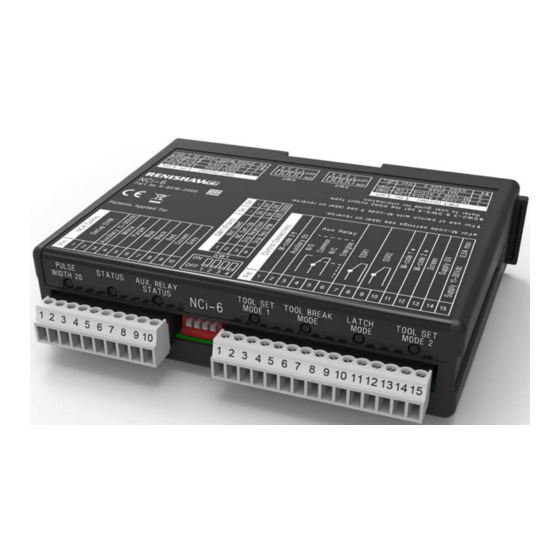
Page 10: Nci-6 Interface Unit (Top Face)
NCi-6 interface unit (top face) Top face interface label Diagnostic LEDs Removable cover Connector CN1 (10-way) Connector CN2 (15-way) NCi-6 interface unit (bottom face) Bottom face interface label NCi-6 non-contact tool setting interface: NCi-6 basics... -
Page 11: Nci-6 Top Label
NCi-6 top label NCi-6 bottom label www.renishaw.com/nci-6... -
Page 12: Connectors Cn1 And Cn2
Used to monitor the signal from the NC unit. Voltage range: 0 Vdc to 9 Vdc. 15-way connector (CN2) Connector CN2 is used to connect the NCi-6 interface to the CNC machine tool . Terminal 1 Used to select the pulse width in consideration with switch SW2-4 . -
Page 13: Interface Leds
Interface LEDs Interface LED states Seven LEDs are fitted on the front of the NCi-6 interface. These provide the operator with a visual indication of the system’s status . Status LED The Status LED indicates the status of the NC system to the operator . The colours and associated states are described in the tables on page 2-6 . -
Page 14: Interface Leds - Status Led
* If the laser beam is clear and the LED is amber, this indicates that the system will continue to function, but for optimum performance maintenance is required . Refer to the applicable installation and user’s guide (for NC4, Renishaw part number H-2000-5230 or NC4+, Renishaw part number H-6270-8501 or NC4+ Blue, Renishaw part number H-6435-8501), for details of the possible actions required . -
Page 15: Switches
Switch locations Removable cover (used to access switches SW2 and SW3 . These switches only need to be accessed during installation) Switch SW1 (used during installation and normal Cover tab – depress to remove cover operation) Switch SW2 Switch SW3 www.renishaw.com/nci-6... -
Page 16: Important: Setting A Switch
M-code 3 may be used to invert the switch setting . NOTE: For the cycle to work, the pulse width value selected must be the same as the value that is configured in the tool setting software . NCi-6 non-contact tool setting interface: NCi-6 basics... -
Page 17: Switch Bank Sw3
NOTE: On certain machine controllers there is a delay between the start of a measurement move and the machine controller becoming responsive to a change in trigger status . In this case use the oscillating output to ensure the trigger is detected when the machine controller becomes responsive . www.renishaw.com/nci-6... - Page 18 This page is intentionally left blank . 2-10 NCi-6 non-contact tool setting interface: NCi-6 basics...
-
Page 19: System Installation
This mode of operation allows functions such as checking tools for missing inserts and profile checking. For further information about the software for these cycles, see Probe software for machine tools, Renishaw part number H-2000-2298 or the relevant Renishaw NCTS software manual for your machine tool . -
Page 20: Pulse Width Setting
Pulse width Pulse width Pulsed Open Closed 20 ms Oscillating Open Closed 20 ms Pulse width = 20 ms or 100 ms, set by SW2-4 Diagrams shown for normally closed, invert for normally open NCi-6 non-contact tool setting interface: System installation... -
Page 21: Tool Set Mode 1 (With Drip Rejection)
< Pulse width Pulse width Closed Pulse width Pulse width Pulsed Open Closed 20 ms Oscillating Open Closed 20 ms Pulse width = 20 ms or 100 ms, set by SW2-4 Diagrams shown for normally closed, invert for normally open www.renishaw.com/nci-6... -
Page 22: Dimensions And Mounting Arrangements
Dimensions and mounting arrangements 34 .6 (1 .36) M4 (×2) Alternative mounting Standard DIN rail mounting Dimensions in mm (in) NCi-6 non-contact tool setting interface: System installation... -
Page 23: Wiring
Wiring Connecting to the NC unit NCi-6 connector CN1 Digital voltmeter Set-up DVM (used only Set-up DVM during NC unit set-up) Auxiliary 11 Vdc to 30 Vdc White Analogue output 1 Purple NC unit Set-up Blue Analogue output 2 Black... -
Page 24: Connecting To The Cnc
0 Vdc CAUTION: If using SSR2 as an oscillating or pulsed output for a trigger signal to the control, the level output SSR1 must be used to guarantee a reliable probe status check . NCi-6 non-contact tool setting interface: System installation... -
Page 25: Controlling The Laser Of An Nc Unit
Controlling the laser of an NC unit This arrangement allows the transmitter of an NC unit system to be switched on and off independently of the receiver . NCi-6 connector CN1 White Analogue output 1 NC unit Purple Set-up Blue... -
Page 26: Sharing The Skip With An Auxiliary Probe
11 Vdc to 30 Vdc supply * High (11 Vdc to 30 Vdc) selects the AUX probe (and may also send the start code). Low (0 Vdc) or floating selects the NC probe. NCi-6 non-contact tool setting interface: System installation... -
Page 27: Controlling The Air Supply To An Nc Unit
Controlling the air supply to an NC unit NC unit Solenoid supply NCi-6 connector CN2 voltage +Vdc Normally open = 200 mA Auxiliary Common relay = 30 Vdc Normally closed Air supply Energise (11 Vdc to 30Vdc) Stimulus, e .g . select M-code *... - Page 28 This page is intentionally left blank . 3-10 NCi-6 non-contact tool setting interface: System installation...
-
Page 29: Maintenance
Maintenance NCi-6 maintenance No routine maintenance is required . Remove dust from the external surfaces with a dry cloth . www.renishaw.com/nci-6... - Page 30 This page is intentionally left blank . NCi-6 non-contact tool setting interface: Maintenance...
-
Page 31: Parts List
Parts list Type Part number Description NCi-6 interface A-6516-2000 NCi-6 interface and box with DIN rail mounting and two terminal blocks . NCi-6 terminal block (10-way) P-CN25-1053 10-way socket terminal for NCi-6 interface . NCi-6 terminal block (15-way) P-CN25-0009 15-way socket terminal for NCi-6 interface . - Page 32 © 2017–2022 Renishaw plc . All rights reserved . This document may not be copied or reproduced in whole or in part, or transferred to any other media or language by any means, without the prior written permission of Renishaw . RENISHAW ®...
Need help?
Do you have a question about the NCi-6 and is the answer not in the manual?
Questions and answers