
Related Manuals for Renishaw OMM-2


Summary of Contents for Renishaw OMM-2
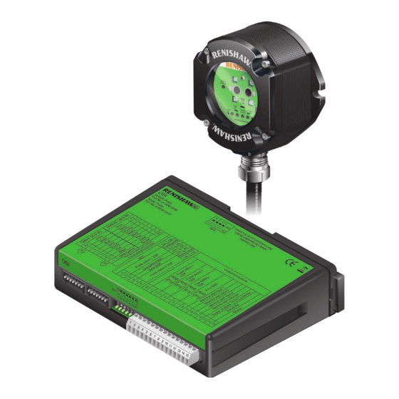
- Page 1 Installation guide H-5492-8504-02-A OSI with OMM-2 multiple optical probe interface system...
- Page 2 © 2010–2018 Renishaw plc. All rights reserved. This document may not be copied or reproduced in whole or in part, or transferred to any other media or language, by any means, without the prior written permission of Renishaw plc. The publication of material within this document does not imply freedom from the patent rights of Renishaw plc.
-
Page 3: Table Of Contents
OSI with OMM-2 system used in multiple probe mode ....... 2.3... - Page 4 OMM-2 cable ............3.4 Installing the OMM-2 to the mounting bracket (optional) ......3.5 Cable sealing .
- Page 5 Removing the OMM-2 window ........
- Page 6 OSI/OMM-2 installation guide This page is intentionally left blank.
-
Page 7: Before You Begin
Trade marks • neglected, mishandled or inappropriately used; RENISHAW and the probe symbol used in the RENISHAW logo are registered trade marks of • modified or altered in any way except with the Renishaw plc in the United Kingdom and other prior written agreement of Renishaw. -
Page 8: Patents
OSI/OMM-2 installation guide Patents Features of OMM-2 and OSI (and features of similar products) are the subject of one or more of the following patents and/or patent applications: EP 0974208 EP 1503524 US 6839563... -
Page 9: Osi Eu Declaration Of Conformity
Renishaw plc or authorised representative could void the user’s authority to operate the equipment. Renishaw plc declares under its sole responsibility that OMM-2 is in conformity with all relevant Union 47 CFR Section 15.105 legislation. This equipment has been tested and found to... -
Page 10: Safety
In all applications involving the use of machine tools or CMMs, eye protection is recommended. Equipment operation The OMM-2 has a glass window. Handle with care If this equipment is used in a manner not specified if broken to avoid injury. -
Page 11: Osi With Omm-2 System Basics
OSI with OMM-2 system basics Introduction The OSI with OMM-2 system operates using a ‘modulated’ optical transmission mode and is compatible with machine probes that also operate in ‘modulated’ mode. CNC machine tools using Renishaw spindle probes with optical signal transmission for... -
Page 12: Osi With Omm-2 System Used In Single Probe Mode
(OTS) instead of the machine application. OMP shown. When the OMM-2 is used in tandem, both receivers will simultaneously provide an OMM-2 (B) OMM-2 (A) (for tandem installation) CNC machine control A typical OSI with OMM-2 system used in single probe mode... -
Page 13: Osi With Omm-2 System Used In Multiple Probe Mode
The OMP is assigned as Probe 1 and 2 × OTS assigned as Probe 2 and Probe 3. OMM-2 (B) (for tandem installation) OMM-2 (A) CNC machine control A typical OSI with OMM-2 system used in multiple probe mode... -
Page 14: System Performance With Omp60 Or Omp600
OSI/OMM-2 installation guide System performance with OMP60 or OMP600 The probe and OMM-2 may deviate from the optical centre line, provided opposing light cones always overlap, with transmitters and receivers in the other’s field of view (eye-to-eye). In multiple probe mode applications, OMP60 or OMP600 may be configured as Probe 1, Probe 2 or Probe 3. -
Page 15: System Performance With Omp40-2, Olp40 Or Omp400
System performance with OMP40-2, OLP40 or OMP400 The probe and OMM-2 may deviate from the optical centre line, provided opposing light cones always overlap, with transmitters and receivers in the other’s field of view (eye-to-eye). In multiple probe mode applications, OMP40-2 or OLP40 may be configured as Probe 1, Probe 2 or... -
Page 16: System Performance With Ots Or Ots Aa
OTS or OTS AA is positioned below the machine spindle. The OTS or OTS AA and OMM-2 may deviate from the optical centre line, provided opposing light cones always overlap, with transmitters and receivers in the other’s field of view (eye-to-eye). -
Page 17: Osi Inputs
When the input is active, the probe is configurable. switched on. The OMM-2 LEDs will start flashing red when an Pulsed 8 V to 30 V (4 mA @ 15 V, 7 mA @ 24 V) The probe toggles between switched output overload has occurred. -
Page 18: Osi Components
Mode configuration switch SW2. the front face of the OSI (as shown in the figure below): Both SW1 and SW2 only need to be accessed during installation. • OMM-2 (A) connector (7-way); • OMM-2 (B) connector (7-way); • Control connector block (15-way); •... -
Page 19: Omm-2 (A) Connector (7-Way)
OMM-2 (A) connector (7-way) This is a seven-pin connector and is designed to connect to the Renishaw OMM-2. OMM-2 (B) connector (7-way) This is a seven-pin connector and is designed to connect to the Renishaw OMM-2. Control connector block (15-way) -
Page 20: Switch Sw1 Output Configuration
OSI/OMM-2 installation guide Switch SW1 output configuration Switch SW1 enables the user to configure the probe system SSR outputs. 2.10 Factory switch settings shown are for A-5492-2000 (multiple probe mode) Pulse Level Probe status 1 SSR Normally open Normally closed... -
Page 21: Switch Sw2 Output Configuration
Switch SW2 output configuration Switch SW2 enables the user to configure the OSI to be used in either single probe mode or multiple probe mode. 2.11 Factory switch settings shown are for A-5492-2000 (multiple probe mode) Switch settings Mode POLE Visual representation Single probe mode, Auto Start off, pulsed machine... -
Page 22: Osi Input Mode Configurations
Machine start input active. When P1 is off, all probes are off. Renishaw probes to be operated. This can be When P1 is active, the selected probe will be on. achieved by using either two or three outputs from the machine controller. -
Page 23: Switch-On / Switch-Off Method
For more information, see your probe installation The maximum time for system recovery from guide or contact your local Renishaw office. an abnormal operating situation is 7.5 seconds. Such a time delay could cause a machine alarm if controllers require ready signals within a time of Switch-on / switch-off method less than 5.5 seconds. -
Page 24: Multiple Probe Mode Timing Diagrams
OSI/OMM-2 installation guide Multiple probe mode timing diagrams Two machine outputs (for three probes) Probe 2 Probe 3 Probe 1 Start Stop Stop Machine start input 1 2.14 Start Stop Start Machine start input 2 10, 50, 100 ms delay options Probe start-up time = 410 ms max. -
Page 25: Osi Output Waveforms
OSI output waveforms Probe Probe Seated Triggered Seated Error Probe 2.15 e.g. switch switch Probe Probe Stand- low signal output trigger reseat battery Stand- Probe status SSR open 1 & 2 (level) Normally SSR closed open Probe status SSR open 1 &... -
Page 26: Osi Dimensions
Up to three Supply voltage 12 Vdc to 30 Vdc Supply current 200 mA max. @ 24 V with tandem OMM-2 Configurable M-code input Pulsed or level Output signals Probe Status 1, Probe Status 2, Low Battery, Error Voltage-free solid-state relay (SSR) outputs, configurable as normally open or normally closed. - Page 27 Maintenance No routine maintenance is required. Remove dust from external surfaces with a dry cloth. CAUTIONS: Power supply voltage 2.17 Do not exceed 30 V between the following: • the black wire and the screen wire (green/ yellow); • the red wire and screen wire (green/yellow); •...
-
Page 28: Omm-2 Components
2.18 operates using ‘modulated’ transmission and is compatible with all machine probes operating in ‘modulated’ mode. The following components are housed within the front window of the OMM-2 (as shown in the figure below): • START SIGNAL LED; • LOW BATTERY LED;... -
Page 29: Start Signal Led (Yellow)
LED is lit. SIGNAL CONDITION LED (red, yellow, green) PROBE STATUS LED (green, red) This tri-colour LED is lit when the OMM-2 is This bi-colour LED is lit when the OMM-2 is powered and indicates as follows. powered. -
Page 30: Range Switch (Sw1)
OSI/OMM-2 installation guide Range switch (SW1) Switch SW1 is user-configurable and can be accessed by removing the window from the front of the OMM-2 (see “Removing the OMM-2 window” on page 4.2). 2.20 Factory switch settings shown are for: •... -
Page 31: Omm-2 Dimensions
OMM-2 dimensions 84 (3.30) 46.7 (1.84) 40 (1.57) 40 (1.57) 2.21 16 (0.63) Dimensions given in mm (in) - Page 32 OMM-2 including 25 m (82 ft) of cable 1500 g (53 oz) Cable The OMM-2 standard cables are 8 m (26 ft), 15 m (49 ft) and 25 m (82 ft) long. Cable specification: Ø5.8 mm (0.23 in), 6-core screened cable, each core 18 × 0.1 mm Mounting A mounting bracket is available allowing directional setting.
-
Page 33: System Installation
System installation Installing the OSI Typical OSI installation OMM-2 (B) (for tandem OMM-2 (A) installation) Cable Cable To CNC machine control OSI interface... -
Page 34: Mounting The Osi To A Din Rail
OSI/OMM-2 installation guide Mounting the OSI to a DIN rail NOTE: Lift spring end plate to attach OSI to DIN rail. Standard DIN rail mounting M4 (× 2) 79.75 (3.14) Alternative mounting Dimensions given in mm (in) -
Page 35: Wiring Diagram (With Output Groupings Shown)
Wiring diagram (with output groupings shown) White Blue Grey OMM-2 Purple Black Green/ Yellow White Blue Grey OMM-2 Purple Black Green/ Yellow Probe Status 1 (SSR) Probe Status 2 (SSR) Low Battery (SSR) machine control Error (SSR) Machine start input 1 (Machine output) -
Page 36: Installing The Omm-2
OSI/OMM-2 installation guide Installing the OMM-2 Power supply Power for the OMM-2 is supplied from the OSI. OMM-2 application OMM-2 cable A single or tandem OMM-2 configuration can be connected to the OSI. Each OMM-2 is connected to the OSI by a 7-way connector block. When a... -
Page 37: Installing The Omm-2 To The Mounting Bracket (Optional)
Installing the OMM-2 to the mounting bracket (optional) Dimensions given in mm (in) (0.98) (0.98) 3 holes Ø6.4 (0.25) 3 grip protrusions 100.5 (3.95) 3 pairs of holes Ø5.3 (0.20) permit OMM-2 mounting in alternative orientation 45° 45 (1.77) (0.08) 90 (3.54) -
Page 38: Cable Sealing
Screw conduit termination piece into the end damage or coolant ingress through the cable of the conduit. cores into the OMM-2. Failure of the product due to inadequate cable protection will invalidate the Fit the conduit to adaptor A and tighten nut B warranty. -
Page 39: Maintenance
Further dismantling and repair of Renishaw transmission. equipment is a highly specialised operation, which must be carried out at authorised Renishaw Service Centres. Equipment requiring repair, overhaul or attention under warranty should be returned to your supplier. -
Page 40: Removing The Omm-2 Window
OSI/OMM-2 installation guide Removing the OMM-2 window Fitting the OMM-2 window It is not necessary to remove the OMM-2 from the Before fitting the window, check for any machine when adjusting the range switch SW1 or damage to screws or scratch marks which installing replacement parts. -
Page 41: Fault-Finding
Correct the M-code and/or wiring or switch off. from machine to OSI and from OSI to OMM-2 and/or CNC program. OMM-2 ERROR LED is lit and Correct the M-codes in the CNC cyan due to ambiguous start program when more than one is information being received. - Page 42 90 minutes. The probe switches on, Interfering light source is shining Remove the source of interference but the OMM-2 ERROR directly into the receiver window. and ensure that the interfering light LED is lit red, blue, does not shine into the receiver yellow or violet.
- Page 43 Installation / CNC program fault. Correct the M-code and/or wiring from machine to OSI and from OSI to OMM-2 and/or CNC program. A signal is being received Change the adjacent probe to low from a probe on an adjacent power mode.
- Page 44 OSI/OMM-2 installation guide This page is intentionally left blank.
-
Page 45: Parts List
OSI (single probe mode) with DIN rail mounting, terminal block and quick-start guide. OMM-2 kit A-5492-0049 OMM-2 with 8 m (26 ft) cable, tool kit and quick-start guide. OMM-2 kit A-5492-0050 OMM-2 with 15 m (49 ft) cable, tool kit and quick-start guide. - Page 46 Quick-start guide: for rapid set-up of the OMP600 optical machine probe. H-5401-8500 Quick-start guide: for rapid set-up of the OTS optical tool setting probe. NOTE: The serial number of each OMM-2 unit is found at the bottom of the housing.
- Page 48 Renishaw plc +44 (0)1453 524524 +44 (0)1453 524901 New Mills, Wotton-under-Edge uk@renishaw.com Gloucestershire, GL12 8JR United Kingdom www.renishaw.com For worldwide contact details, visit www.renishaw.com/contact *H-5492-8504-02* Issued: 10.2018 Part no. H-5492-8504-02-A © 2010–2018 Renishaw plc...
Need help?
Do you have a question about the OMM-2 and is the answer not in the manual?
Questions and answers