
Related Manuals for Renishaw NCi-6


Summary of Contents for Renishaw NCi-6
- Page 1 Installation and user’s guide H-6516-8500-01-A NCi-6 non-contact tool setting interface...
- Page 3 Publications for this product are available by visiting www.renishaw.com/nci-6. Weitere Informationen zu diesem Produkt sind unter folgendem Link www.renishaw.de/nci-6 abrufbar. Las publicaciones para este producto están disponibles a través de www.renishaw.es/nci-6. Les documentations pour ce produit sont disponibles en visitant le site www.renishaw.fr/nci-6.
- Page 4 This page is intentionally left blank.
- Page 5 English Installation and user’s guide NCi-6 non-contact tool setting interface...
- Page 6 This page is intentionally left blank.
- Page 7 Renishaw products and technologies are trade marks of The publication of material within this document does not Renishaw plc or its subsidiaries. imply freedom from the patent rights of Renishaw plc. All other brand names and product names used in this Disclaimer document are trade names, trade marks, or registered trade marks of their respective owners.
- Page 8 Patents Unless otherwise specifically agreed in writing between Features of the NCi-6 non-contact interface and related you and Renishaw, if you purchased the equipment from products are subject to the following patents and patent a Renishaw company, the warranty provisions contained applications: in Renishaw’s CONDITIONS OF SALE apply.
- Page 9 This device complies with Part 15 of the FCC rules. Operation is subject to the following two conditions: Renishaw plc declares that the NCi-6 non-contact interface complies with the applicable standards and This device may not cause harmful interference, and regulations.
- Page 10 Before you begin Safety Information to the equipment installer All Renishaw equipment is designed to comply with the Information to the user relevant EC and FCC regulatory requirements. It is the In all applications involving the use of machine tools or responsibility of the equipment installer to ensure that CMMs, eye protection is recommended.
- Page 11 Use of controls or adjustments or performance of procedures other than those specified within this publication may result in hazardous radiation exposure. Switch off electrical power to the NCi-6 interface before carrying out maintenance on non-contact (NC) tool setting and tool breakage detection products.
- Page 12 General information NCi-6 maintenance Operating conditions No routine maintenance is required. Protection provided by IP20 enclosure BS EN 60529:1992+A2:2013 Remove dust from the external surfaces with a dry cloth. (IEC 60529:1989+A1:1999+ A2:2013). Electrical ratings Altitude Maximum 2000 m (6562 ft) Operating temperature +5 °C to +55 °C...
-
Page 13: Table Of Contents
General ............................3 Introduction ..........................3 Power supply ......................... 3 Input / output over-current protection ..................3 NCi-6 interface unit (top face) ....................4 NCi-6 interface unit (bottom face) ..................5 NCi-6 front label ........................6 NCi-6 back label ........................7 Connectors CN1 and CN2 ...................... - Page 14 Contents High-speed tool breakage detection ..................18 Latch mode .......................... 18 Mode selection ........................19 Pulse width setting ......................20 Tool set mode 1 (without drip rejection) ................21 Tool set mode 1 (with drip rejection) ..................22 Tool set mode 2 ........................23 Dimensions and mounting arrangements ..................
-
Page 15: General
General Introduction The supply to the NCi-6 is protected by a 0.5 A resettable fuse. To reset the fuse, remove the CNC machine tools using Renishaw NC4 or power then identify and rectify the cause of the NC4+ non-contact (NC) systems for tool setting or fault. -
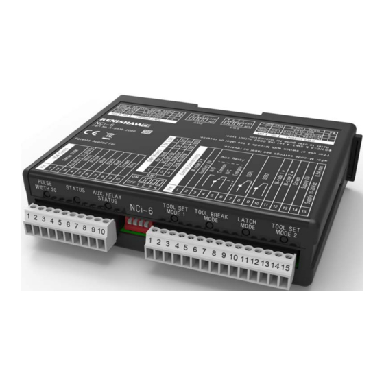
Page 16: Nci-6 Interface Unit (Top Face)
General NCi-6 interface unit (top face) Top face interface label Removable cover Diagnostic LEDs Connector CN1 (10-way) Connector CN2 (15-way) -
Page 17: Nci-6 Interface Unit (Bottom Face)
General NCi-6 interface unit (bottom face) Bottom face interface label... -
Page 18: Nci-6 Front Label
General NCi-6 front label... -
Page 19: Nci-6 Back Label
General NCi-6 back label... -
Page 20: Connectors Cn1 And Cn2
(N.C.). The output is fused at 50 mA. 15-way connector (CN2) Terminals 9 – 10 Connector CN2 is used to connect the NCi-6 This is an SSR output that can be configured to interface to the CNC machine tool. be either normally open (N.O.) or normally closed Terminal 1 (N.C.), as well as providing a pulsed, level or... -
Page 21: Interface Leds
Interface LEDs Interface LED states Seven LEDs are fitted on the front of the NCi-6 interface. These provide the operator with a visual indication of the system’s status. Status LED The Status LED indicates the status of the NC system to the operator. The colours and associated states are described in the table on pages 11 and 12. -
Page 22: Mode Leds: (Tool Set 1, Tool Break, Latch And Tool Set 2)
Tool set 1, Tool break, Latch and Tool set 2) Green Mode selected Not lit Mode not selected For more information see page 18, “Operating modes”. NOTE: If no mode LEDs are lit, this indicates that the NCi-6 interface is in set-up mode. -
Page 23: Interface Leds - Status Led
If the laser beam is clear and the LED is Refer to the applicable installation and user’s guide amber, this indicates that the system will continue (for NC4, Renishaw part number H-2000-5230 or to function, but for optimum performance NC4+, Renishaw part number H-6270-8501), for maintenance is required. - Page 24 If the laser beam is clear and the LED is Refer to the applicable installation and user’s amber, this indicates that the system will continue guide (for NC4, Renishaw part number to function, but for optimum performance H-2000-5230 or NC4+, Renishaw part number maintenance is required.
-
Page 25: Switches
Switches Switch locations Removable cover (used to access switches SW2 and SW3. These switches only need to be accessed during installation) Cover tab – depress to remove cover Switch SW1 Switch SW2 (used during installation and normal operation) Switch SW3... -
Page 26: Switch Settings - Sw1
Switches IMPORTANT: Setting a switch When setting a switch to either the On or Off position, apply firm pressure to make sure it is fully in position. Switch bank SW1 Not used Not used. NC set-up Used when setting up an NC4 or NC4+ system. Set this switch to On so that the alignment voltage can be maximised. -
Page 27: Switch Settings - Sw2
Switches Switch bank SW2 CAUTIONS: With the SSR output switch(es) set to Off, i.e. normally open (N.O.), the respective output will remain in a non-triggered state if the power supply is interrupted and/or a poor connection is made to the SSR. If using SSR2 as an oscillating or pulsed output for a trigger signal to the control, the level output SSR1 must be used to guarantee a reliable probe status check Switch... -
Page 28: Switch Settings - Sw3
Switches Switch bank SW3 Switch M-code 1 High Determines whether the input responds to an active – high or active – low signal. Active M-code 1 High As above. Active Not used – – Not used. SSR2 Osc. Sets the SSR2 output to oscillating or as per SW2-3. Refer to the page 17. -
Page 29: Ssr2 Output Selections
SSR2 output selections SSR2 type 1 and SSR2 type 2 NOTE: On certain machine controllers there is a delay between the start of a measurement move and the machine controller becoming responsive CAUTION: If using SSR2 as an oscillating or to a change in trigger status. -
Page 30: Operating Modes
It uses For further information about the software for “Dual Measurement” technology. Measurement these cycles, see www.renishaw.com takes place as the tool exits the laser beam providing shorter cycle times and is more robust in wet conditions. -
Page 31: Mode Selection
Operating modes Mode selection These modes can be activated using M-codes M-code 1 (tool breakage) supplying a constant voltage of between 11 Vdc M-code 2 (latch mode) and 30 Vdc connected to CN2-11 and/or CN2-12 3 kΩ 3 kΩ Screen (see the table below). -
Page 32: Pulse Width Setting
Operating modes Pulse width setting • Sets the minimum r/min of the tools in tool set mode 1, without drip rejection active, and The pulse width setting has the following in tool set mode 2. functions: • Switch SW2-4 sets the pulse width to 20 ms •... -
Page 33: Tool Set Mode 1 (Without Drip Rejection)
Operating modes Tool set mode 1 (without drip rejection) Tool setting without drip rejection Beam clear Beam blocked Beam clear Beam clear Beam blocked Blocks Clears Blocks Laser Clears status < Pulse width > Pulse width Level Open Closed Pulse width Pulse width Pulse width Pulsed... -
Page 34: Tool Set Mode 1 (With Drip Rejection)
Operating modes Tool set mode 1 (with drip rejection) Tool setting with drip rejection Beam clear Beam clear Beam blocked Beam clear Beam blocked by drips Clears Blocks Blocks Clears Laser status Drip filter Drip filter < Drip filter Level Open Closed Pulse width... -
Page 35: Tool Set Mode 2
Operating modes Tool set mode 2 Tool setting (drip rejection not applicable) Beam blocked Beam clear Blocks Clears Blocks Laser Clears status > Pulse width Level Open < Pulse width Pulse width Closed Pulse width Pulse width Open Pulsed Closed 20 ms Oscillating Open... -
Page 36: Dimensions And Mounting Arrangements
Dimensions and mounting arrangements 34.6 (1.36) M4 (×2) Alternative mounting Standard DIN rail mounting Dimensions in mm (in) -
Page 37: Wiring
Wiring NC4 or NC4+ system NCi-6 connector CN1 Digital voltmeter (used Set-up DVM only during Set-up DVM NC4 or NC4+ Auxiliary 11 Vdc to 30 Vdc set-up) White Analogue output 1 NC4 or NC4+ Purple Set-up Blue Analogue output 2... -
Page 38: Connecting To The Cnc
Wiring Connecting to the CNC NCi-6 connector CN2 M-code 3 (reverses switch SW2-4) Not used (auxiliary 0 V) Normally open Auxiliary Common relay Normally closed machine Energise (11 Vdc to 30 Vdc) control SSR1 voltage-free SSR1 voltage-free SSR2 voltage-free SSR2 voltage-free... -
Page 39: Controlling The Laser Of An Nc4 Or Nc4+ System
This arrangement allows the transmitter of an Controlling the laser of an NC4 or NC4 or NC4+ system to be switched on and off NC4+ system independently of the receiver. NCi-6 connector CN1 White Analogue output 1 Purple NC4 or NC4+... -
Page 40: Sharing The Skip With An Auxiliary Probe
Wiring Sharing the skip with an auxiliary probe NCi-6 connector CN2 Aux. probe output Normally open Output (probe status) Auxiliary Common Machine skip input relay Normally closed Energise (11 Vdc to 30 Vdc) Select M-code * SSR1 voltage-free machine SSR1 voltage-free... -
Page 41: Controlling The Air Supply To An Nc4 Or Nc4+ System
Wiring Controlling the air supply to an NC4 or NC4+ system NC4 or NC4+ Solenoid supply NCi-6 connector CN2 voltage +Vdc Normally open = 200 mA Auxiliary Common relay = 30 Vdc Air supply Normally closed Energise (11 Vdc to 30 Vdc) Stimulus, e.g. -
Page 42: Parts List
Parts list Type Part number Description NCi-6 interface and box with DIN rail mounting and two NCi-6 interface A-6516-2000 terminal blocks. NCi-6 terminal block P-CN25-1053 10-way socket terminal for NCi-6 interface. (10-way) NCi-6 terminal block P-CN25-0009 15-way socket terminal for NCi-6 interface. - Page 43 Renishaw plc +44 (0)1453 524524 New Mills, Wotton-under-Edge +44 (0)1453 524901 Gloucestershire, GL12 8JR uk@renishaw.com www.renishaw.com United Kingdom For worldwide contact details, visit www.renishaw.com/contact *H-6516-8500-01*...
Need help?
Do you have a question about the NCi-6 and is the answer not in the manual?
Questions and answers