Table of Contents
Advertisement
Quick Links
Advertisement
Table of Contents

Subscribe to Our Youtube Channel
Related Manuals for Renishaw OMI-2H


Summary of Contents for Renishaw OMI-2H
- Page 1 Installation guide H-5157-8504-01-B OMI-2H optical machine interface...
- Page 2 This document may not be copied or reproduced in whole or in part, or transferred to any other media or language, by any means, without the prior written permission of Renishaw plc. Renishaw plc. Registered in England and Wales. Company no: 1106260. Registered office: New Mills, Wotton-under-Edge, Gloucestershire, GL12 8JR, UK.
-
Page 3: Table Of Contents
OMI-2H visual diagnostics ........ - Page 4 Removing the OMI-2H window ........
-
Page 5: Before You Begin
Renishaw office. Renishaw warrants its equipment and software for a limited period (as set out in the Standard Terms and Conditions), provided that they are installed and used exactly as defined in associated Renishaw documentation. -
Page 6: Care Of The Interface
Keep system components clean. Patents None applicable. Intended use The OMI-2H, which acts as a combined optical transceiver and machine interface, converts signals from the optical probe into a voltage-free solid state relay (SSR) output for transmission to the CNC machine controller. Safety Information to the user In all applications involving the use of machine tools, eye protection is recommended. - Page 7 The product was evaluated and classified using the following standard: BS EN 62471:2008 The photobiological safety of lamps and lamp systems. Renishaw recommends that you do not stare at or look directly into any LED device, irrespective of its risk classification.
- Page 8 OMI-2H installation guide This page is intentionally left blank.
-
Page 9: Omi-2H Basics
‘Modulated’ mode. Power supply The OMI-2H can draw its supply from the CNC machine’s nominal 12 Vdc to 30 Vdc supply. The maximum peak supply current is 160 mA when the OMI-2H is transmitting. The average supply current is 40 mA when the OMI-2H is receiving. -
Page 10: Omi-2H Visual Diagnostics
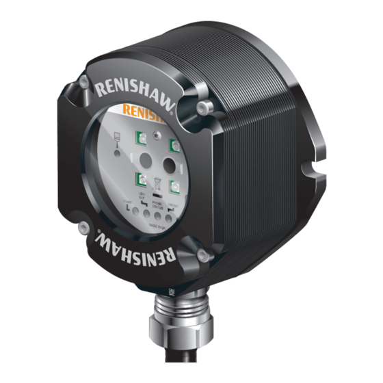
OMI-2H installation guide OMI-2H visual diagnostics A visual indication of system status is provided by LEDs. Indication is provided for: • START; • LOW BATTERY; • PROBE STATUS; • ERROR; • SIGNAL; • ACTIVE SYSTEM. PROBE STATUS LED ACTIVE SYSTEM... -
Page 11: Start Signal Led (Yellow)
(Probe 1 or Probe 2) is deactivated. SIGNAL CONDITION LED (red, yellow, green) This tricolour LED is lit when the OMI-2H is powered and indicates as follows: – No communication: There is no signal from the probe. -
Page 12: Omi-2H Inputs
Do not exceed 30 V between the black wire and the screen wire, or the red wire and screen wire, or the red and black wires (power supply); as this could result in permanent damage to the OMI-2H and/ or the customer power supply. -
Page 13: Omi-2H Output Waveform
OMI-2H output waveform Seated Triggered Seated Probe Probe Probe Probe switch Probe switch trigger Standby battery reseat Standby Start inputs Active Probe 1 Inactive Active Common Probe 2 Inactive SSR output Probe status SSR open (level) SSR closed Normally closed Signal delays 1. -
Page 14: Switch Sw2
OMI-2H installation guide Switch SW2 NOTE: To gain access to the switch, remove the window (for more information see “Removing the OMI-2H window” in Section 4, “Maintenance”). Switch SW2 output configuration START RANGE RANGE NOT USED NOT USED 100% NOT USED... -
Page 15: Switch On / Switch Off
Switch on / switch off method The OMI-2H operates using only optical on / optical off as the switch on / switch off method. Optical on / optical off is available with all Renishaw’s OMP range of spindle probes and the optical tool setter (OTS). -
Page 16: Omi-2H Dimensions
OMI-2H installation guide OMI-2H dimensions 46.7 (1.84) 84 (3.30) 40 (1.57) 40 (1.57) 16 (0.63) Dimensions given in mm (in) -
Page 17: Omi-2H Specification
OMP600 and OTS Operating range Up to 6 m (19.7 ft) Weight OMI-2H including 8 m (26.2 ft) of cable = 720 g (25.40 oz) Supply voltage 12 Vdc to 30 Vdc (for more information, see “Wiring diagram” in Section 3, “System installation”) Supply current Transmitting: 160 mA max. - Page 18 OMI-2H installation guide 2.10 This page is intentionally left blank.
-
Page 19: System Installation
100.5 (3.95) 3 pairs of holes Ø5.3 (0.20) permit OMI-2H mounting in an alternative orientation 45° 45 (1.77) 90 (3.54) (0.08) Dimensions given in mm (in) NOTE: Install OMI-2H with cable exiting from lower side for good coolant run off. -
Page 20: Wiring Diagram
OMI-2H installation guide Wiring diagram OMI-2H Grey Purple Probe status (SSR) White Machine start input (Probe 1) Blue Machine start input (Probe 2 12 V to 30 V Power supply (12 V to 30 V) Black Green/yellow Screen Machine ground (“star point”) CAUTIONS: The power supply 0 V should be terminated at the machine ground (“star point”). -
Page 21: Omi-2H Cable
NOTE: Maximum length of the specified cable must not exceed 25 m (82 ft). Cable sealing Coolant and dirt are prevented from entering the OMI-2H by the cable sealing gland. The OMI-2H cable can be protected against physical damage by fitting a flexible conduit if required. -
Page 22: Fitting Flexible Conduit
OMI-2H installation guide Fitting flexible conduit Adaptor A Conduit termination piece Cable Plastic olive Flexible Nut B conduit NOTE: Conduit bulkhead fittings require a clearance hole for an M16 thread. Slide nut B and the plastic olive onto the conduit. -
Page 23: Screw Torque Values Nm (Lbf.ft)
Screw torque values Nm (lbf.ft) × 2 3.0 mm A/F 2 Nm (1.47 lbf. ft) × 2 4.0 mm A/F 8.0 mm A/F 5 Nm (3.68 lbf. ft) 22.0 mm (7/8 in A/F) 22 Nm (16.22 lbf. ft) MAXIMUM... - Page 24 OMI-2H installation guide This page is intentionally left blank.
-
Page 25: Maintenance
Wipe the window of the interface with a clean cloth to remove machining residue. This should be done on a regular basis to maintain optimum transmission. CAUTION: The OMI-2H has a glass window, handle with care if broken to avoid injury. -
Page 26: Removing The Omi-2H Window
Remove the four cover screws, using a 2.5 mm A/F hexagon key. Two screws are short and two are long. Two of the cover holes are threaded A, and two are plain B. The window fits tightly on the OMI-2H body, and is removed using the two long screws, which are inserted into the threaded holes A. -
Page 27: Fitting The Omi-2H Window
Before fitting the window, check for any damage to screws or scratch marks which could prevent sealing. Ensure the O-ring seating C in the OMI-2H body is clean. Ensure that the O-ring D and window E are clean. Insert the two short screws into window holes A, and tighten. - Page 28 OMI-2H installation guide This page is intentionally left blank.
-
Page 29: Fault-Finding
The probe is out of the start Change the CNC program to bring range. the probe within the start range of the OMI-2H and ensure that the appropriate start range is selected. The transmission beam is Clean the OMI-2H window and obstructed. - Page 30 Remove the obstruction. mid-cycle. obstructed. Optical interference. Remove the source of interference An unexpected error or reposition the OMI-2H such that occurs during a interfering light does not shine into probing cycle. the OMI-2H window. An unexpected trigger Intermittent wiring fault.
- Page 31 A signal is being received from Change the adjacent probe to a probe on an adjacent machine low power mode or change the tool. OMI-2H reception range to 50%, if this range is acceptable. Probe triggers but The OMP400 or OMP600 has Reconfigure the OMP400...
- Page 32 OMI-2H installation guide This page is intentionally left blank.
-
Page 33: Parts List
Installation guide: for the set up of the OMP60. OMP600 A-5180-8504 Installation guide: for the set up of the OMP600. A-5401-8504 Installation guide: for the set up of the OTS. NOTE: The serial number of each OMI-2H unit is found at the bottom of the housing. - Page 34 Renishaw plc +44 (0)1453 524524 +44 (0)1453 524901 New Mills, Wotton-under-Edge, uk@renishaw.com Gloucestershire, GL12 8JR United Kingdom www.renishaw.com For worldwide contact details, visit www.renishaw.com/contact Issued: 12: 2022 Part no. H-5157-8504-01-B © 2016–2022 Renishaw plc...
Need help?
Do you have a question about the OMI-2H and is the answer not in the manual?
Questions and answers