Table of Contents
Advertisement
Quick Links
Advertisement
Table of Contents

Summary of Contents for Renishaw MI5
- Page 1 H-2000-5014-05-E MI 5 Interface Unit...
- Page 2 Installation and User's Guide MI 5 Interface Unit...
-
Page 3: Fcc Declaration (Usa)
Renishaw The user is cautioned that any changes or modifications product documentation, and to ensure that adequate not expressly approved by Renishaw plc, or authorised guards and safety interlocks are provided. representative could void the user's authority to operate the equipment. - Page 4 SIKKERHED Informationen für den Benutzer Oplysninger til brugeren Anleitungen über die sichere Reinigung von Se afsnittet VEDLIGEHOLDELSE (MAINTENANCE) Renishaw-Produkten sind in Kapitel WARTUNG i produktdokumentationen for at få instruktioner (MAINTENANCE) in der Produktdokumentation til sikker rengøring af Renishaw-produkter. enthalten. Udskift sikringer, der er sprunget, med nye Durchgebrannte Sicherungen müssen mit...
- Page 5 Informations à l’attention de l’utilisateur Para instrucciones sobre seguridad a la hora de Les conseils de nettoyage en toute sécurité limpiar los productos Renishaw, remitirse a la des produits Renishaw figurent dans la section sección titulada MANTENIMIENTO (MAINTENANCE) MAINTENANCE de votre documentation.
- Page 6 ´ ´ ´ ´ Koneen toimittaja on velvollinen selittämään ´ käyttäjälle mahdolliset käyttöön liittyvät vaarat, ´ ´ ´ mukaan lukien Renishaw’n tuoteselosteessa ´ ´ ´ mainitut vaarat. Toimittajan tulee myös varmistaa, ´ ´ ´ ´ ´ että toimitus sisältää riittävän määrän suojia ja ´...
- Page 7 Renishaw, e di mettere a disposizione i ripari in de produktendocumentatie van Renishaw. di sicurezza e gli interruttori di esclusione.
- Page 8 Renishaws produktdokumentation, incluindo os mencionados na documentação do samt att tillräckligt goda skydd och produto Renishaw e assegurar que são fornecidos säkerhetsförreglingar tillhandahålls. resguardos e interbloqueios de segurança adequados. Em certas circunstâncias, o sinal da sonda pode Under vissa omständigheter kan sondens...
-
Page 9: Warranty
MI 5 Installation … … … CHANGES TO EQUIPMENT Wiring Diagram for SSR outputs … Renishaw reserves the right to change specifications without notice. Alternative TTL and OCT outputs … CNC MACHINE CNC machine tools must always be operated LP2 Hard Wired Inspection System by competent persons in accordance with manufacturers instructions. -
Page 10: Tool Setting
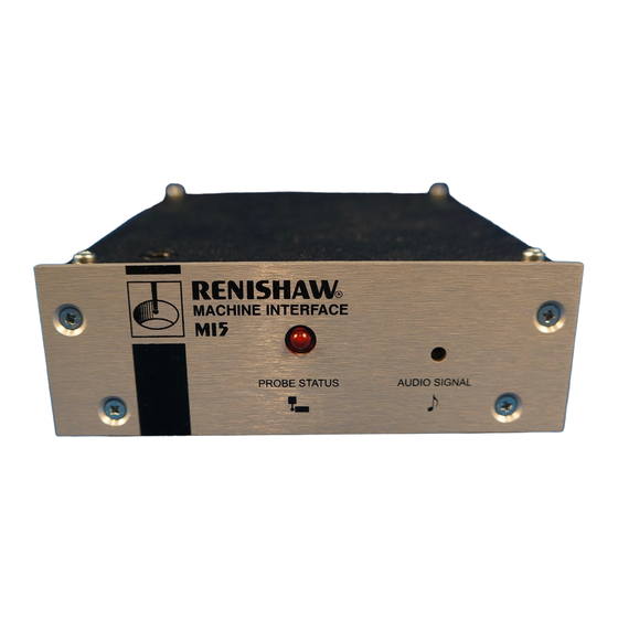
MI 5 INTERFACE UNIT CNC machine tools using a Renishaw probe system for tool setting or workpiece set-up and inspection require an interface unit, to convert probe signals into an acceptable form for the CNC machine control. The MI 5 interface unit is part of probe systems using hard wired or inductive signal transmission. - Page 11 Remote Audible Indicator or LED The MI 5 interface processes signals from Renishaw probes and converts the signals into voltage free If the MI 5 is installed where it not be easily seen,...
- Page 12 Single Hard Wired Tool Setting Probe Operation up to 200mA. Alternatively it can be powered from See probe input linking on terminals 18 and 19 (page 1-4). a Renishaw PSU3 Power Supply Unit. Single Inductive Inspection Probe Operation Note : Incorrect polarity of the DC supply See probe input linking on terminals 21 and 22 (page 1-4).
- Page 13 WIRING DIAGRAM (The wiring configuration of this unit differs from earlier models) 3 Wires 16/0.2 Insulated 1 Chassis 200mA (T) Anti-Surge Green 2 0V Unit Supply FS2 FS3 Black 3 18-30V DC 63mA (F) 63mA (F) 4 A O/P Scrn Quick Blow Quick Blow 5 A O/P...
- Page 14 Red, Green, Blue and Yellow. See table opposite for connections. Overall diameter 4,3mm (0,17in). MACHINE Maximum length 30m (98ft). CONTROL CNC MACHINE CONTROL Please consult Renishaw when cable length CONNECTIONS FOR TWO PROBES ONLY exceeds 30m (98ft). INDUCTIVE TRANSMISSION M Code INHIBITS M Code Inductive Module Machine (IMM) to interface.
-
Page 15: Ttl Output
ALTERNATIVE TTL and OCT OUTPUTS TTL OUTPUT To provide TTL 0,5mA max levels, connect two 16mA max resistors 5k6 and 2K0, and MI 5 hard wire link 4,8V max Interface terminals 9 to 18. 3,2V min Machine Unit Control 0,7V max 0V min All resistors 0,25W... - Page 16 Remote socket Lemo Part No. CNC MACHINE CONTROL TO ENSURE OPERATOR SAFETY EGG 1K 303 CNL It is recommended that a fail safe HIGH Renishaw Part No. Spindle rotation SPINDLE ROTATION INHIBIT P/CN21/0303 Inhibited 0,25W is built into the machine Connect to Pin 3 installation.
-
Page 17: Output Signal
OUTPUT SIGNAL The output signal from the interface Contact bounce Reseat must be compatible with machine PROBE STATUS control. OUTPUT The two output devices are identical OPTIONS and have the following specification: Trigger Move point clear Solid State Relay (SSR) Normally Closed (N/C). - Page 18 DIMENSIONS mm (in) 131 (5,16) (1,77) (1,93) 178 (7,00) 21 (0,83) Securing bolt position for surface mounting Two holes Ø6,3 (0,25) (4,17) Cable Glands (0,94) To suit cable Ø5-7mm (Ø0,20 - 0,27in) 3 (0,12) 28 (1,1) 135 (5,31) PARTS LIST - Please quote the Part No. when ordering equipment. Type Part No.
- Page 19 Fax +41 55 410 66 69 Germany. Internet http://www.renishaw.com Renishaw Inc, Tel +49 7127 9810 623 Cooper Court, Fax +49 7127 88237 Renishaw Latino Americana Ltda., Schaumburg, Illinois 60173, Calçada dos Crisântemos 22, Renishaw S.p.A., U.S.A. C.C. Alphaville, C.e.p. 06453-000, Via dei Prati 5,...


Need help?
Do you have a question about the MI5 and is the answer not in the manual?
Questions and answers