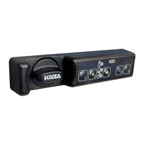
Kaba Mas Unicon CL20 Installation Instructions
Cl series, wood spring latch bolt
Hide thumbs
Also See for Unicon CL20:
- Installation instructions (2 pages) ,
- Installation instructions (2 pages) ,
- Operating instructions manual (17 pages)
Advertisement
Installation Instructions for Unicon
Front Housing
Assembly
Short Mounting Posts (2)
Mounting Post
Screws (2)
Long
Mounting
Posts (2)
Trim Plate
Chamber
Assembly
Screws (2)
Chamber Assembly
Figure 1 - Unicon CL10/CL20 Wood Spring Latch Bolt Lock Parts
These installation instructions are intended for a standard install. Please
refer to the Kaba Mas web site for installation variations.
Prepare for New Installation of the Lock (If Required)
1. Use the template provided to
prepare the mounting surface for lock
installation. Complete steps A, B, and
C.
2.
Check the width and length of the
drilled lock mounting hole to ensure
that the back mounting plates will fit
correctly. (Figure 2)
TM
CL Series Locks - Models CL10, CL20 - Wood Spring Latch Bolt Installation
Back Mounting
Follower
Plate Screws (2)
Guide
Cross Throw Follower
End Throw Follower
Spring
Bolt Hardware
Bolt Guide
Bolt
Screws (2)
Strike
Back
Mounting
Strike Screws (3)
Plates
Install Lock
1. Place mounting posts on housing
assembly and attach with 1/2" thread
forming screws (without star washers.)
(Figure 4) For 1/2" thick mounting
surfaces, use the short mounting
Figure 2
posts. For 5/8"-7/8" thick mounting
surfaces, use the long mounting
posts.
Note: Ensure that the screw holes of the
mounting posts align with the screw holes
in the front housing assembly.
2. Orient the trim plate to the correct position in alignment with the
housing assembly, and feed the cable through the middle hole.
(Figure 5) Place the flat side toward the front housing assembly.
Figure 5
3. Place the trim plate over the mounting posts.
4. Plug the cable into the chamber assembly. (Figure 6)
Basic Tools and Materials Needed
•
Drill (variable speed is best)
•
1" drill bit or 1" hole saw
•
1/16" (1.6mm) drill bit
•
Scribe, awl, center punch, or sharp
instrument for marking holes
Cross
•
Small flat head screwdriver
Throw
•
Small Phillips head screwdriver
Cam
(recommend magnetized tip)
•
Jig saw (Keyhole saw or coping saw
optional)
End
•
Fine cut wood file and rasp
Throw
•
Pencil
Cam
•
Tape measure or ruler
•
Tape
•
ESD wrist band
Mounting
WARNING: Kaba Mas locks are protected
from 25,000 V Electrostatic Discharge
(ESD) damage when correctly installed.
Follow these precautions to avoid ESD
damage when installing the lock:
• Do not touch the circuit board wthin the
front housing assembly.
• Use an ESD wrist band grounded to the
lock or container during installation.
Figure 6
5. Insert the spindle shaft into the front housing. (Figure 7)
Note: You may have to turn the knob to engage the spindle. Do not
push the cable back through into the front housing assembly.
Ensure that the cable stays in place under the chamber.
Figure 7
6. Install the 4-40 x 3/8" rear
mounting screw (away from the
spindle) to attach the chamber to
the front housing. (Figure 8)
7. Place the assembly through the
opening in the door with the knob
toward the bolt location. (Figure 9)
*******************************************
For an End Throw Installation:
(See back of sheet for Cross Throw.)
8. Place the cam (marked by an E
on the back surface) onto the
control shaft, with the post closest to
the bolt location. (Figure 10)
9. Insert follower guide into the slot
on the chamber. (Figure 11)
10. Pivot the follower guide down
Figure 4
halfway and insert the follower into the slot. (Figure 12)
Figure 11
11. Feed the spring onto the back of the follower and set against the
riveted bracket. (Figure 13)
Figure 13
12. Move the follower forward until it engages the cam post.
(Figure 14)
Figure 8
Figure 9
Figure 10
Figure 12
Figure 14
Document # 3070.026 Rev. B - 03/07
Advertisement
Table of Contents

Related Manuals for Kaba Mas Unicon CL20


Summary of Contents for Kaba Mas Unicon CL20
- Page 1 These installation instructions are intended for a standard install. Please 9. Insert follower guide into the slot on the chamber. (Figure 11) refer to the Kaba Mas web site for installation variations. 1. Place mounting posts on housing assembly and attach with 1/2” thread 10.
- Page 2 (Figure 28 - End Throw, Figure 29 - Cross Throw) Figure 21 Figure 22 © 2006-2007 Kaba Mas Corporation. All rights reserved. Product warranty information can be found at: www.kaba-mas.com Kaba Mas Corporation 749 W. Short Street, Lexington, KY 40508 USA...
Need help?
Do you have a question about the Unicon CL20 and is the answer not in the manual?
Questions and answers