Table of Contents
Advertisement
Quick Links
Certification Exhibit
FCC ID: 2AHFM-BTCENMDB
IC: 21164-BTCENMDB
FCC Rule Part: 15.247
IC Radio Standards Specification: RSS-247
ACS Project Number: 15-3053
Manufacturer: Kaba Mas LLC
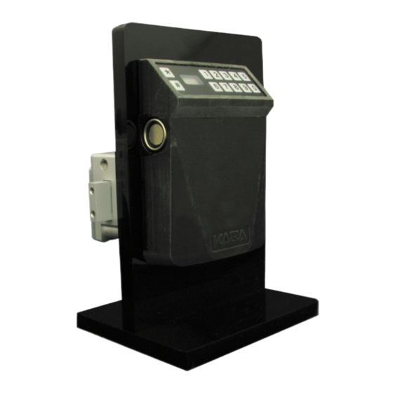
Model: Cencon MDB 30N
Manual
2320 Presidential Drive, Suite 101, Durham, NC 27703 USA Voice: 919-381-4235 Fax: 770-831-8598
Advertisement
Table of Contents

Related Manuals for Kaba Mas Cencon MDB 30N


Summary of Contents for Kaba Mas Cencon MDB 30N
- Page 1 FCC ID: 2AHFM-BTCENMDB IC: 21164-BTCENMDB FCC Rule Part: 15.247 IC Radio Standards Specification: RSS-247 ACS Project Number: 15-3053 Manufacturer: Kaba Mas LLC Model: Cencon MDB 30N Manual 2320 Presidential Drive, Suite 101, Durham, NC 27703 USA Voice: 919-381-4235 Fax: 770-831-8598...
- Page 2 INSTALLATION INSTRUCTIONS PRELIMINARY 05/26/2016 CENCON Motorized Dead Bolt ATM Security Lock...
-
Page 3: Table Of Contents
ABLE OF ONTENTS INTRODUCTION ............4 CENCON LOCK PARTS FOR INSTALLATION ....5 BASIC TOOLS AND MATERIALS NEEDED ............5 PREPARE FOR NEW INSTALLATION OF THE LOCK ........5 PART I - INSTALL FRONT HOUSING ASSEMBLY ..6 PART II - INSTALL LOCK CASE ASSEMBLY....8 PART III - INTERCONNECT BOX INSTALLATION .. -
Page 4: Introduction
NTRODUCTION Please read all instructions carefully before you install and use your Cencon ATM Security Lock. This will help you avoid unnecessary costs and concerns resulting from improper installation. The installation instructions are the basis for Security Agency Approvals. The lock installation must be done in accordance to these instructions in order to maintain the labeled approval level. -
Page 5: Cencon Lock Parts For Installation
® • Loctite 262 (Red) for use on lock case mounting screws WARNING: Kaba Mas locks are protected from 25,000 V Electrostatic Discharge (ESD) damage when correctly installed. Follow these precautions to avoid ESD damage when installing the lock: • Handle the keypad assembly by the outer edge only. -
Page 6: Part I: Install Front Housing Assembly
I: I NSTALL RONT OUSING SSEMBLY Install Instructions for Cencon Motorized Deadbolt Entry Assembly 1. Use the dimensions provided in Figure 2 to establish the exact locations (relative to the spindle hole) of the mounting holes for the Entry Device and the lock assembly. Be sure to consider the cable length from the entry device to the lock. 2. The spindle hole diameter can be a minimum of .406” (10.3mm) to a maximum of .438” (11.1mm). The .406” (10.3mm) diameter is recommended. Spindle hole must be deburred. 3. The Entry Device mounting screws require drilled and tapped holes to 3/8” (9.5mm) depth if possible (minimum 1/4” or 6.4mm depth required.) (Figure 2 – Hole Locations. Not to scale) 4. Screw the two mounting studs into the stud mounting holes just drilled. Tighten to approximately 15-20 inch-pounds. -
Page 7: Part Ii: Install Lock Case Assembly
Figure 3 - Mounting Stud Alignment II: I NSTALL SSEMBLY WARNING: Do not take the lock case assembly apart. This action will void the lock warranty. 1. Ensure the cables lay in the cable channel as you mount the lock case assembly to the inside of the container door using the three 1/4-20 (or M6-1) screws (Torque 25-30 lbs., 2.8-3.4 N-M), allowing 1/20”... - Page 8 AFTER LOCK CASE INSTALLED Warning: Do not insert batteries into input unit prior to having all connections into lock secured. Also, ensure no power is applied to the 24V terminal prior to all connections being completed. 1. Attach Power Cable to lock while not connected to power supply. Insert the red wire into +24 Volt terminal and tighten screw terminal with small lathead screwdriver.
-
Page 9: Part Iii: Interconnect Box Installation
III: I NTERCONNECT NSTALLATION PTIONAL All connections made to the lock are keyed by plastic ribs on the side of NOTE: the connectors. Strain relief should be applied to all cables as necessary. 1. Attach the 8 pin serial connector to the lock case and then to the Interconnect Box. -
Page 10: Basic Lock Operations
ASIC PERATIONS For the complete Cencon lock and software operating instructions in FLM, Route, and Bank modes, please see the Cencon Reference Manual on the documentation section at www.kaba-mas.com. Opening Lock in Shelved Mode Each lock is shipped from the factory in Shelved Mode. The “one time only” combination feature is not available when the lock is shelved. -
Page 11: Change The Shelved Mode Combination
Change the Shelved Mode combination You may change the default Factory Combination of 50-25-50 to a new combination to be used while the lock is still in Shelved Mode. Once you have changed the combination for the irst time, you may want to change the combination again to a different Shelved Mode combination. -
Page 12: Gen2 Lock Menu Command List
10. Press * Key → CLb Press * key until CLb is displayed. 11. Close Container Door 12. Extend Bolt → CLo Rotate the container handle to extend the bolt. The lock will display “---” while the bolt is moving. The bolt will stop moving when it reaches the closed position and the lock will display CLo. 13. Press * Key → EC Press * key until the letters EC (Enter Combination) appear in the display window. 14 EC → Enter New Shelved Mode Combination → OPn Enter the new shelved mode combination by pressing those digits on the lock’s keypad. The numbers will be displayed as they are entered. The lock will display “---” while the bolt is moving. The bolt will stop moving when it reaches the open position and the lock will display OPn. 15. -
Page 13: Cencon Lock Lcd Terminology
Previous to a lock being activated in any mode, the prompts ##, #4, and #70, 72, 76, 78 and 79 will display the error. #72 only applies to Gen2 locks activated with a USB Key Box. After a particular mode is shelved, the ## and #4 prompts will still display “” to give information about a mode the last time it was active, though the remaining #7x prompts mentioned will start showing the error again. -
Page 14: Query The Lock Via The Keypad
The UTC/GMT date and time are initialized in a Gen2 lock at the time of manufacture at Kaba Mas. When #71 is pressed, the current lock date & time are displayed. This display can be canceled by pressing the asterisk (*) key, or it will automatically be... - Page 15 For each of the commands that displays either current or historic Date and Time (#71, #72, #78, and #79), the format is the same: Starting from the largest time increment (4-digit Year) and moving down to the smallest (2-digit second). For readability, the date and the time are broken apart by the “Hr-”...
-
Page 17: Document Number 2112.0315 Rev. A -Preliminary
Notice: The information in this manual is subject to change without notice and does not represent a commitment on the part of Kaba Mas. Kaba Mas shall not be liable for technical or editorial errors or omissions contained herein; nor for incidental or consequential damages resulting from the furnishing, performance or use of this material.
Need help?
Do you have a question about the Cencon MDB 30N and is the answer not in the manual?
Questions and answers