Table of Contents
Advertisement
Quick Links
Advertisement
Table of Contents

Related Manuals for Kaba Mas Low Profile 52 series


Summary of Contents for Kaba Mas Low Profile 52 series
- Page 1 NSTALLATION UIDE ROFILE...
-
Page 2: Table Of Contents
NINSTALL THE EYPAD SSEMBLY WARNING: Kaba Mas locks are well protected from Electrostatic Discharge (ESD) damage once they are installed, but can be damaged during the installation process if proper precautions are not observed. Follow these precautions to avoid ESD damage when installing the lock: •... -
Page 3: Introduction
You should read all instructions carefully before you install and use your Low Profile 52 Series lock. This will help you avoid unnecessary costs and concerns resulting from improper installation. These installation instructions apply to all Low Profile 52 Series Models (Self Powered and Battery). Design Parameters for Locks 1. -
Page 4: Basic Tools And Materials Needed
Basic Tools and Materials Needed • Medium (#2) and Small Phillips head screwdriver (magnetized tip recom- mended) • Fine pitch hacksaw (32 teeth/inch) • Small flat file • Pliers • All-purpose scissors • Tape measure or ruler Recommended, but not required: •... -
Page 5: Lock Parts For Installation
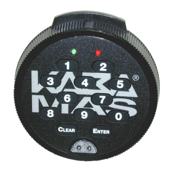
Lock Parts for Installation 1. Lock case assembly 2. Keypad assembly 3. Dial assembly (with home position decal attached to back) 4. Lock case mounting screws (4 for Battery, 3 for Non-Battery) 5. Dial assembly mounting screws (2) 6. Keypad assembly mounting screws (2) 7. -
Page 6: Installation
NSTALLATION Install the Lock Warning: Do not take the lock case assembly apart. There are no field servicable parts inside lock case. Complete the following steps to install the lock: 1. Insert a cable shield into the spindle hole from the back side of the container door. - Page 7 8. Tape the flex cable to the outside of the tube with the insulator tape provided in the installation kit. 9. While holding the lock case assembly, again carefully guide the end of the flex cable and the tube through the inside of the container so that they are easily accessible at the outside of the container.
- Page 8 18. For Dead Bolt: Insert the spring end of the spindle into the container with the grooved side facing towards the extended bolt. (Figure 5) For Spring Bolt: Insert the end of the spindle with the screw hole into the lock case assembly until the spindle is properly seated.
- Page 9 Gear Shield Flex Cable Figure 11 - Cable must be outside of Figure 10 - Guide flex cable gear shield through cable receiving hole 22. Align the dial assembly with the spindle and hold the dial assembly against the container door. Attach the dial assembly to the container door using the two dial assembly mounting screws and the Phillips screwdriver.
- Page 10 Figure 13 - Open ZIF connector Figure 14 - Close ZIF connector and insert flex cable 24. Carefully fold the excess flex cable and position it in the center area of the lock case so that the cable will not be pinched by the gears (Figure 15).
-
Page 11: Install Battery Clip & Battery
INSTALL BATTERY CLIP & BATTERY (Battery or Battery Assist Locks Only) 1. Remove tape backing from the tape on the battery clip. 2. Mount the battery clip. 3. Connect a fresh 9 Volt Alkaline battery to the battery connector. 4. Insert the battery into the battery clip. TEST LOCK Test the operation of the lock before completing the installation of the keypad assembly decal and prior to closing the container by verifying the following:... - Page 12 25. If the lock does not operate successfully, carefully unscrew the keypad assembly and check the flex cable connection. Also ensure that the flex cable is not getting pinched. 26. After you have successfully tested the lock operation, ensure that the keypad mounting screws have been tightened.
-
Page 13: Uninstall The Keypad Assembly
Figure 18 - Remove keypad decal 4. If the lock still does not operate successfully, contact Kaba Mas Technical Support at 1 (800) 950-4744. - Page 15 OTES...
- Page 16 Notice: The information in this manual is subject to change without notice and does not represent a commitment on the part of Kaba Mas. Kaba Mas shall not be liable for technical or editorial errors or omissions contained herein; nor for incidental or consequential damages resulting from the furnishing, performance or use of this material.
Need help?
Do you have a question about the Low Profile 52 series and is the answer not in the manual?
Questions and answers