
Related Manuals for Generac Power Systems LINKTower PLT240


Summary of Contents for Generac Power Systems LINKTower PLT240
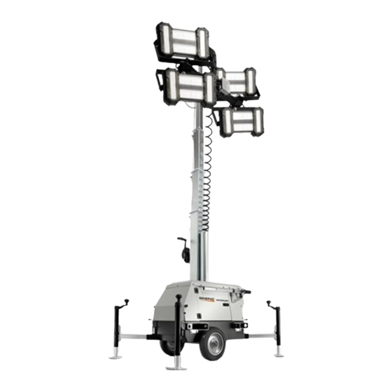
- Page 1 Owner’s Manual Light Tower PLT240 LINK Tower 003986 For technical assistance contact: www.generacmobileproducts.com Technical Support 1-800-926-9768 SAVE THIS MANUAL FOR FUTURE REFERENCE...
- Page 2 Use this page to record important information about your Light Tower Record the information found on your unit data label on this page. See unit serial number location (Unit Serial Unit Model Number Number Locations). The data plate is affixed to the mast inside the cabinet.
-
Page 3: Table Of Contents
Table of Contents Section 1: Introduction and Safety Section 4:Maintenance Introduction ............1 Daily Walk-Around Inspection ......17 Read This Manual Thoroughly ........1 General Maintenance ........17 How to Obtain Service ..........1 Preparing for Service ..........17 Safety Rules ............1 Cleaning the Unit ............17 Inspecting the Unit .............17 General Hazards ..........2 Basic Maintenance Schedule ...... - Page 4 Table of Contents This page intentionally left blank. Owner’s Manual for PLT240 Light Tower...
-
Page 5: Section 1: Introduction And Safety
Introduction and Safety Section 1: Introduction and Safety Introduction Safety Rules Thank you for purchasing a Generac Mobile Products LLC The manufacturer cannot anticipate every possible product. This unit has been designed to provide high circumstance that might involve a hazard. The warnings in performance, efficient operation, and years of use when this manual, and on tags and decals affixed to the unit are, maintained properly. -
Page 6: General Hazards
Introduction and Safety General Hazards Electrical Hazards DANGER WARNING Electrocution. In the event of electrical accident, Moving Parts. Keep clothing, hair, and immediately shut power OFF and disconnect unit appendages away from moving parts. Failure from source. Use non-conductive implements to free to do so could result in death or serious injury. -
Page 7: Starting The Unit
Introduction and Safety Starting the Unit DO NOT perform even routine maintenance unless all electrical components are shut down. DANGER • ALWAYS use extreme care when servicing this unit in damp conditions. Do not service the unit if your Electrocution. DO NOT use the unit if skin or clothing is wet. - Page 8 Introduction and Safety Figure 1-1. Decal Locations Owner’s Manual for PLT240 Light Tower...
-
Page 9: Section 2: General Information Specifications
General Information Section 2: General Information Specifications DESCRIPTION PLT240-LED Dimensions Unit Dimensions Weights Operating Weight 558 lbs (252.6 kg) Lighting Lighting Type Light-Emitting Diode (LED) LED Driver (4) Mean Well HLG-320H-30A Lumens 88,000 AC Distribution Circuit Breaker Size 15A / 20A Main Breaker Amperage Selection 15A / 20A 120V-20 Amp GFCI Receptacle... -
Page 10: Unit Serial Number Locations
General Information Unit Serial Number Locations Figure 2-1 to locate the unit ID tag on the unit. Important information, such as the unit serial number, model number, and tire loading information are found on these tags. Record the information from these tags so it is available if the tags are lost or damaged. -
Page 11: Unit Dimensions
General Information Unit Dimensions 003440 Figure 2-2. Unit Dimensions 54 in. 77.5 in. 16 ft. 31.5 in. 57 in. 74 in. PLT240 (1.37 m) (1.96 m) (4.88 m) (0.80 m) (1.45 m) (1.88 m) Specifications are subject to change without notice. Owner’s Manual for PLT240 Light Tower... -
Page 12: Component Locations
General Information Component Locations 003443 Figure 2-3. Component Locations—Front and Left Side Forklift pockets / tie-down locations LED Drivers (inside cabinet) Swiveling caster (lockable) Lockable storage access door (2) Control panel Outrigger and jack (4) Water protection shield Handle (2) Quick start guide Winch LED fixtures (4) -
Page 13: Control Panel
General Information Control Panel IMPORTANT NOTE: If the control panel is ever removed, replace the gasket behind control panel and the gasket between the water ingress cover and control panel. 003389 Figure 2-4. Control Panel Control Panel Components and Functions (E) 120VAC/20A GFCI convenience receptacle (5-20R) Customer convenience receptacle for use in connecting (A) Main circuit breaker... -
Page 14: Internal Storage
General Information Internal Storage 4. Close and lock both access doors and the control panel. Figure 2-5. The interior of the cabinet can be used 5. See Figure 2-6. To lift the unit, use one of the for storing nonflammable items such as shore power following methods: cords, small equipment, or tools when the unit is not in •... -
Page 15: Tying The Unit Down
General Information Figure 2-8. The chassis is equipped with a swiveling caster at the rear. Step on the brake (E) to lock the caster and prevent the wheel from rotating. Raise the brake to unlock the caster. 003515 Figure 2-8. Swiveling Caster Tying the Unit Down When securing the unit for transportation, verify the equipment being used to fasten the unit is in good... - Page 16 General Information This page intentionally left blank. Owner’s Manual for PLT240 Light Tower...
-
Page 17: Section 3:Operation
Operation Section 3: Operation Operation Configuration DANGER Before setting up the unit, determine if the unit will Asphyxiation. Do not connect any engine- operate as a standalone light tower, or if export power will powered equipment or fired air heaters to the be required. -
Page 18: Raising The Mast
Operation 6. See Figure 3-1. Pull the locking pins (A) on the four outriggers (B) and pull each outrigger out until the spring loaded locking pin snaps back into place. STOP DETAIL C 003544 Figure 3-1. Set Up Outriggers and Jacks 7. -
Page 19: Prestart Checklist
Operation Prestart Checklist WARNING Before starting the unit, all items in the prestart checklist Machine damage. Do not extend the mast beyond must be completed. the colored mark. Overextension can stretch or break electrical cables or winch cables, and may WARNING damage mast hardware. -
Page 20: Turn Unit On
Operation Turn Unit ON Long-Term Storage Perform the following steps if the machine is to be stored DANGER for an extended period (for example, more than one Electrocution. DO NOT use the unit if year). electrical cord is cut or worn through. Doing 1. -
Page 21: Section 4:Maintenance
Maintenance Section 4: Maintenance Daily Walk-Around Inspection Inspecting the Unit • If the unit is stored outside, check for water inside Perform a walk-around inspection of the unit every day the cabinet and control panel cover before each before starting the unit. Look for conditions that could use. -
Page 22: Winch Use, Operation And Maintenance
Maintenance Winch Use, Operation and Winch Mechanical Brake Maintenance The mechanical brake generates heat when loads are lowered and the wire cable is powered out. Care must be taken to avoid overheating the mechanical brake. Prior to Use Whine or chatter associated with a new mechanical •... -
Page 23: Section 5:Troubleshooting
Troubleshooting Section 5: Troubleshooting Troubleshooting the Lights IMPORTANT NOTE: Only a qualified electrician should DANGER troubleshoot or repair electrical problems occurring in this Electrocution. Potentially lethal voltages are present equipment. Contact Generac Mobile Products Technical in this equipment. Render the equipment safe before Service at 1-800-926-9768 for assistance if you have any attempting repairs or maintenance. - Page 24 Troubleshooting This page intentionally left blank. Owner’s Manual for PLT240 Light Tower...
-
Page 25: Section 6:Wiring Diagrams
Wiring Diagrams Section 6: Wiring Diagrams AC Wiring GN/YL GN/YL GN/YL GN/YL DRIVER 4 TB B4 RD/YL BK/YL LIGHT #4 DRIVER 3 RD/WT TB B3 BK/WT LIGHT #3 RD/BL BK/BL TB B2 NEUTRAL RD/OR LIGHT #2 DRIVER 2 BK/OR TB B1 LIGHT #1 DRIVER 2 TB A4... - Page 26 Wiring Diagrams This page intentionally left blank. Owner’s Manual for PLT240 Light Tower...
- Page 28 Part No. 54800 Rev. C 06/01/17 ©2017 Generac Mobile Products All rights reserved. Specifications are subject to change without notice. Generac Mobile Products No reproduction allowed in any form without prior written 215 Power Drive, Berlin, WI 54923 consent from Generac Mobile Products. GeneracMobileProducts.com │800-926-9768 │920-361-4442...
Need help?
Do you have a question about the LINKTower PLT240 and is the answer not in the manual?
Questions and answers