Table of Contents
Advertisement
EVERLAST
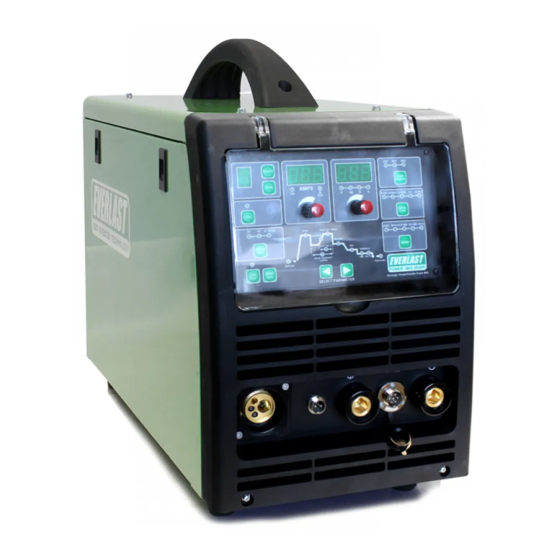
POWER i-MIG 253DPi
A Digitally-Controlled Synergic Pulse MIG with Stick Function
CC
CV
GMAW
SMAW
IGBT
DC
PULSE
Operator's Manual for the Power i-MIG 253DPi
Safety, Setup and General Use Guide
Rev. 1
0 10613-18
everlastwelders.com
Specifications and Accessories subject to change without notice.
1-877-755-9353
329 Littlefield Ave. South San Francisco, CA 94080 USA
Advertisement
Table of Contents

Subscribe to Our Youtube Channel
Related Manuals for Everlast POWER i-MIG 253DP


Summary of Contents for Everlast POWER i-MIG 253DP
- Page 1 EVERLAST POWER i-MIG 253DPi A Digitally-Controlled Synergic Pulse MIG with Stick Function GMAW SMAW IGBT PULSE Operator’s Manual for the Power i-MIG 253DPi Safety, Setup and General Use Guide Rev. 1 0 10613-18 everlastwelders.com Specifications and Accessories subject to change without notice.
-
Page 2: Table Of Contents
Table of contents Section……………………………………………….Page Letter to the Customer …………………..………… Everlast Contact Information…………….…………. Safety Precautions…………………………………… Introduction and Specifications…..………………… Overview of Parameters and Specifications……. Technical Parameters……………………………... General Description, Purpose and Features……. Set Up Guide and Component Identification….…... Suggested Settings…….…………………...…….. Connections and Polarity…………………………. - Page 3 It is also important so that we may track your satisfaction with Everlast products and services. If you are unable to register by web- site, contact Everlast directly through the sales department at the main customer service number in your country.
- Page 4 Date of Purchase:___________________________ Contact Information Everlast US: Everlast consumer satisfaction email: sales@everlastwelders.com Everlast Website: everlastwelders.com Everlast Technical Support: tech@everlastwelders.com or support@everlastwelders.com Everlast Support Forum: http://www.everlastgenerators.com/forums/index.php Main toll free number: 1-877-755 WELD (9353) 9am—5pm PST M-F 11am-4pm PST Sat. FAX: 1-650-588-8817 Everlast Canada: Everlast consumer satisfaction email: sales@everlastwelders.ca...
-
Page 5: Safety Precautions
Safety Precautions Everlast is dedicated to providing you with the best possible equipment and service to meet the de- mands of the welding applications that you have. We want to go beyond delivering a satisfactory prod- uct to you. That is the reason we offer free North American based technical support to assist you with your needs should an occasion occur. - Page 6 Safety Precautions These safety precautions are for protection of safety and health. Failure to follow these guidelines may result in serious injury or death. Be careful to read and follow all cautions and warnings. Protect yourself and others. Welding and cutting processes produce high levels of ultraviolet (UV) radiation that can cause se- vere skin burn and damage.
- Page 7 Safety Precautions WARNING! Persons with pacemakers should not weld, cut or be in the welding area until they consult with their physician. Some pacemakers are sensitive to EMF radiation and could severely malfunction while welding or while being in the vicinity of someone welding. Serious injury or death may occur! Welding and plasma cutting processes generate electro-magnetic fields and radiation.
- Page 8 Safety Precautions WARNING! Electrical shock can kill. Make sure all electrical equipment is properly grounded. Do not use frayed, cut or otherwise damaged cables and leads. Do not stand, lean or rest on ground clamp. Do not stand in water or damp areas while welding or cutting. Keep work surface dry. Do not use welder or plasma cutter in the rain or in extremely humid conditions.
-
Page 9: Introduction And Specifications
.040” to .045” (1.0mm to 1.2mm) for Aluminum, and Bronze (brazing) use. ** Additional Drive Rolls may be ordered direct from Everlast ( 2 pc kit). Size and type stamped on side of the drive roll next to the related groove for easy identification. Synergic Pulse settings for Mild Steel, Stainless Steel, 40XX series Aluminum, 50XX series Aluminum, and Bronze wires. - Page 10 Section 1 Introduction and Specifications EVERLAST POWER i-MIG 253DPi SERIAL NO. MODEL: POWER i-MIG 253DPi EN/ IEC60974.1 DC: 40-250 A; 16-30V 100% 250 A 195 A 80 V 26.5 V 23.8 V DC: 10-200 A; 20.4-28 V 100% 250 A...
-
Page 11: General Description, Purpose And Features
For easy set-up and recall of the most commonly used or synergic modes. These additional guns are available settings this welder is capable of storing up to 10 pro- directly from Everlast and offer the best choice for grams. This is useful when multiple operators are us- welding aluminum. - Page 12 Section 1 Introduction and Specifications equipped with optional serrated drive rolls. How- ing the same welder or when different thicknesses and ever, if Flux-Core is used in synergic mode and syn- metal types are changed on a frequent basis. When ergic Pulse modes, the welder will not operate cor- needing to save parameters, particularly with multiple rectly.
- Page 13 IGBT inverter design that wire will not feed the wire until the Pre-Flow time is produces a stable arc while conserving energy. Everlast satisfied. Add more flow time if porosity or oxida- utilizes quality components from US, European, and...
- Page 14 Section 1 Introduction and Specifications best service and results while welding: 1) Do not use the welder in damp or wet areas. Per- spiration and other forms of water in contact with the body can increase the risk of shock or electro- cution.
-
Page 15: Set Up Guide And Component Identification
(located under the access cover). WORK WORK CONTROL SPOOL GUN + ** Push Pull gun and Spool gun are optional items that may be purchased separately from Everlast. PUSH-PULL GUN** STICK PUSH/PULL GUN + WORK TORCH WORK... - Page 16 Section 2 Setup Guide and component Identification GENERAL POLARITY RECOMMENDATIONS* Table 1 *Consult the manufacturer of the filler material recommendations concerning polarity . PROCESS TORCH POLARITY WORK POLARITY MIG (GMAW) FLUX CORE (FCAW) STICK (SMAW) Table 2 GAS SELECTION GUIDE PROCESS MIG (GMAW) STEEL For best operation in Synergic Pulse Spray:...
-
Page 17: Installing The Wire Spool
NOTE: An adapter/spacer will be needed to use 8” spools. Contact Everlast to purchase one if you do not have an adapter. To install the MIG gun (torch). A.Align pins on the torch connector with the feeder receptacle. -
Page 18: Front View Main Panel
Section 2 Setup Guide and component Identification FRONT VIEW/ MAIN PANEL POWER i-MIG 253DPi PULL MOTOR CONTROL... -
Page 19: Front Panel Item Description And Explanation
Keep in mind that when you are adjusting Amp chine does not reset, check the fuse. If the fuse is output, you are also adjusting wire speed. good, call Everlast tech support for further diag- While wire speed is commonly used as a refer- nosis procedures. - Page 20 Section 2 Setup Guide and component Identification know complex algorithms or to have extensive In the non-pulse synergic mode, the unit defaults experience at setting up complex parameters to Steel operation and does not allow selection for related to MIG welding, especially Pulse parame- other Filler metal types since it is assumed that ters.
- Page 21 Section 2 Setup Guide and component Identification will be highlighted. It is only represented by a factory programming to be reloaded. Do not “relative” range of inductance control and not a access this function casually! Be aware that quantified amount. This function is discussed more accessing this function without the proper later in the manual.
- Page 22 Section 2 Setup Guide and component Identification program number you have saved and the basic 10. Parameter Selector Buttons. The left and right settings you wish to preserve in case you acci- arrow buttons adjust parameters located in the dentally resave over an old program. graph (item 11) located directly above the 13.
- Page 23 Section 2 Setup Guide and component Identification trode negative polarity (Straight Polarity). Connect Connect the MIG torch by aligning pins on the to the work clamp while in MIG/Stick mode. gun cable with the receptacle and pushing in. Twist the collar on the cable connector to lock in Features found in Weld Cycle Graph (item #11) from left place.
- Page 24 Section 2 Setup Guide and component Identification spatter. A low setting of 2 to 3 can be helpful with rods high end. Arc force control is also known as induct- such as E7018, 7014, and 6013. E6011 benefits from a ance control, slope or wave form control (MIG).
- Page 25 Section 2 Setup Guide and component Identification Setting the “base” layer too high will result in little pud- 253DPi, this value is represented by “Hertz” or “Hz”. dle cooling. This will manifest itself in too much puddle Hertz is the international standard used to represent fluidity.
- Page 26 Section 2 Setup Guide and component Identification 10. Burn-Back Volts/Volt Offset. This feature ad- justs the Burn-Back Voltage or Voltage Offset/Trim. During Burn-Back, the Amps are not relevant since amps are a function of wire-speed and wire feeding is stopped during the Burn-Back process. Depending upon desired effect, and trimming requirements, the Burn–Back Volts/Volt Offset function should be set lower than or equal to the setting used for Welding.
-
Page 27: Side View
Section 2 Setup Guide and component Identification SIDE VIEW POWER i-MIG 253DPi... - Page 28 If you do not have an adapt- wire. Do NOT over lubricate! Your unit has been er, contact Everlast to purchase one. NOTE: 4” supplied with additional drive roll sizes. Do not rolls of wire are not supported.
-
Page 29: Rear View Back Panel
Section 2 Setup Guide and component Identification REAR VIEW/BACK PANEL POWER i-MIG 253DPi FUSE 1x220V... -
Page 30: Rear Panel Item Description And Explanation
“clean power” and provide less than 5% THD. Consult your generator manufac- turer for information regarding the clean power rating on specific units. Everlast does not pro- vide a list of approved generators. Manufactur- ers rate their units as clean power independent- ly according to industry standards. -
Page 31: Basic Mig Operation
Section 2 Setup Guide and component Identification BASIC MIG OPERATION General Setup of Amps and Volts. equal (Volts, metal thickness, type, etc.). A smaller When you MIG weld with almost any basic MIG wire will require a faster wire speed to produce the welder, there are generally two main adjustments same Amps. - Page 32 If these sounds are present, look at the While Everlast uses the term “inductance” on this arc to see if it is steady, and producing low amounts model, it is known by many different terms. On of spatter.
- Page 33 Section 2 Setup Guide and component Identification BASIC MIG OPERATION wire contacts the puddle and the current falls. This ance allows this machine to have excellent arc process is happening many times a second so it isn’t performance when pure CO2 is used in non- usually visible to the naked eye.
- Page 34 Section 2 Setup Guide and component Identification BASIC MIG OPERATION spend time trimming the wire. Even if the wire does vation. not stick in the puddle, it will often be left sticking too far out from the contact tip for a proper restart. Starting the Arc and Welding.
- Page 35 Section 2 Setup Guide and component Identification BASIC MIG OPERATION humped appearance if not done correctly or if travel tain a sound weld. The removal of paint, rust mill is too slow. Whenever MIG welding with Alumi- scale, or other contaminate such as grease should num, whether with the standard MIG gun or the be done before welding.
- Page 36 Section 2 Setup Guide and component Identification BASIC MIG OPERATION passes. The weldment edges should be ground to form a V, U or J shaped groove to create a recess where the welds can be welded one on top of anoth- er.
- Page 37 Section 2 Setup Guide and component Identification BASIC MIG OPERATION Besides a butt joint and lap joint which are often used V-GROOVE (60-80°) DOUBLE V-GROOVE for thinner metal gauges, consider using one of these groove joints for best welding results. When grinding or cutting the bevels, especially with a single V- groove, it may be beneficial to leave a small land with U-GROOVE...
- Page 38 Section 2 Setup Guide and component Identification BASIC MIG OPERATION Problem: Gun is not being held vertical from side to side. Wire is not being directed to the center of the puddle. This concentrates heat on one side of the joint and results in poor fusion on the neglected side.
- Page 39 Section 2 Setup Guide and component Identification BASIC MIG OPERATION Characteristics: Concave weld, poor filling, possi- ble undercutting resulting in weak weld. Possible Causes: Voltage too high, not enough wire speed, too short of wire stick out, wrong gun angle. Remedy: Decrease voltage, use push motion, in- crease wire speed.
-
Page 40: Pulse Mig Operation
DC. With a regulated welding performance. To under- double-pulse MIG, the unit simply pulses be- stand the Everlast Pulse MIG design and setup, tween a higher layer and a lower layer of sin- it is important to recognize and discuss basic gle pulse MIG. - Page 41 Section 2 Setup Guide and component Identification PULSE MIG OPERATION heat being put into the weld and over the di- rectabilty of the arc. The basic reason for us- Historically, the most common applications for ing a single-pulse MIG is to prevent over- single Pulse-MIG welding are found in Alumi- heating of the weld metal while maintaining a num or Stainless Steel fabrication or repair.
- Page 42 Section 2 Setup Guide and component Identification PULSE MIG OPERATION prevent incomplete fusion. All MIG welding is rameters taken out of the control of the user, done, regardless of transfer method is com- and only allow minor fine tuning by the user, if monly done with Argon, or more rarely, an Ar- any at all.
- Page 43 (often referred to as a ropy weld). sics of Synergic operation. In Synergic Single Pulse MIG mode, the Power i-MIG 253DPi can As you use the Everlast welder in pulse mode, be compared to other types of Synergic single- the average voltage value is roughly between...
- Page 44 Section 2 Setup Guide and component Identification PULSE MIG OPERATION file. It also automatically sets a balance of tive to the other two remaining functions. Due time that is split between the two levels of to the complexities and endless combinations Voltage.
- Page 45 Section 2 Setup Guide and component Identification PULSE MIG OPERATION setting without giving you an indication that no workable setting for the Voltage Offset or you may be nearing the “sweet spot” for the Inductance has been found. Avoid radical setting.
- Page 46 Section 2 Setup Guide and component Identification PULSE MIG OPERATION performance. 40 to 60% as an initial setting range. To set Amps properly in the Double Pulse, first set Peak Pulse amps as you would for welding Pulse MIG and Inductance. Whether in Single in Single Pulse normally, and up to 20% higher Pulse Mode or Double Pulse Mode do not fo- if desired.
-
Page 47: Mig Control Features
Section 2 Setup Guide and component Identification MIG Control Features of the Power i-MIG 253DPi Gun Operation and Features Controlled in Standard Non-Pulse MIG Mode Gun Trigger Pre-Flow Hot Start Peak Pulse Frequency Pulse Inductance Welding End Arc Burn Back Burn Post Flow Mode... - Page 48 Section 2 Setup Guide and component Identification MIG Control Features of the Power i-MIG 253DPi Single Pulse and Non-Pulse 2T WELDING BURNBACK TIME VOLTS PREFLOW POSTFLOW Single Pulse and Non-Pulse 4T WELDING BURNBACK TIME VOLTS PREFLOW POSTFLOW Single Pulse 4T Special HOT START WELDING BURNBACK...
- Page 49 Section 2 Setup Guide and component Identification MIG Control Features of the Power i-MIG 253DPi Double Pulse 2T PEAK WELDING BURNBACK TIME VOLTS PREFLOW POSTFLOW Double Pulse 4T PEAK WELDING BURNBACK TIME VOLTS PREFLOW POSTFLOW Double Pulse 4T Special HOT START PEAK /ARC FORCE WELDING BURNBACK...
- Page 50 Peak Amps offset, range 100-150A Peak Time offset, range 1.5-3.0ms Base Amps offset, range 10-40A Wire Run in Speed, 0-10. 10 is no run in. Reload factory default settings The factory synergic settings do allow some corrective adjustment. But they have been care- fully chosen for best overall operation and should not normally need to be adjusted.
-
Page 51: Pulse Mig Work Sheets
Section 2 Setup Guide and component Identification PULSE MIG OPERATION PULSE WORKSHEETS Use the following worksheets to save and record your pulse settings for different metals and wire diameters. Or, you may use it to create your own additional spread sheet of settings. - Page 52 Section 2 Setup Guide and component Identification PULSE MIG OPERATION Single Pulse MIG Work Sheet 1 Stainless Grade ______ Metal Thickness Wire Diameter Hot Start Amps Voltage/Offset Inductance End A/V Burn Back Burn Back PGM # Time Offset NOTES:...
- Page 53 Section 2 Setup Guide and component Identification PULSE MIG OPERATION Single Pulse MIG Work Sheet 2 Steel Grade ______ Metal Thickness Wire Diameter Hot Start Amps Voltage/Offset Inductance End A/V Burn Back Burn Back PGM # Time Offset NOTES:...
- Page 54 Section 2 Setup Guide and component Identification PULSE MIG OPERATION Single Pulse MIG Work Sheet 3 Aluminum Grade ______ Metal Thickness Wire Diameter Hot Start Amps Voltage/Offset Inductance End A/V Burn Back Burn Back PGM # Time Offset NOTES:...
- Page 55 Section 2 Setup Guide and component Identification PULSE MIG OPERATION Single Pulse MIG Work Sheet 4 Bronze Grade ______ Metal Thickness Wire Diameter Hot Start Amps Voltage/Offset Inductance End A/V Burn Back Burn Back PGM # Time Offset NOTES:...
- Page 56 Section 2 Setup Guide and component Identification PULSE MIG OPERATION Double Pulse MIG Work Sheet 5 Stainless Grade ______ Metal Wire Hot Start Peak Pulse Pulse Welding Inductance Burn Burn PGM # Thickness Diame- Amps/ Amps/ Time Frequency Amps/ Amps / Back Back Offset...
- Page 57 Section 2 Setup Guide and component Identification PULSE MIG OPERATION Double Pulse MIG Work Sheet 6 Steel Grade ______ Metal Wire Hot Start Peak Pulse Pulse Welding Inductance Burn Burn PGM # Thickness Diame- Amps/ Amps/ Time Frequency Amps/ Amps / Back Back Offset...
- Page 58 Section 2 Setup Guide and component Identification PULSE MIG OPERATION Double Pulse MIG Work Sheet 7 Aluminum Grade ______ Metal Wire Hot Start Peak Pulse Pulse Welding Inductance Burn Burn PGM # Thickness Diame- Amps/ Amps/ Time Frequency Amps/ Amps / Back Back Offset...
- Page 59 Section 2 Setup Guide and component Identification PULSE MIG OPERATION Double Pulse MIG Work Sheet 8 Bronze Grade ______ Metal Wire Hot Start Peak Pulse Pulse Welding Inductance Burn Burn PGM # Thickness Diame- Amps/ Amps/ Time Frequency Amps/ Amps / Back Back Offset...
-
Page 60: Stick Operation
Section 2 Setup Guide and component Identification STICK OPERATION STARTING METHODS Scratch/Match Method Tapping Method 1. Make sure the unit is turned on and the startup cycle has finished. 2. Select the appropriate Stick icon on the Process Selector. 3. Make sure electrode holder is in in the Positive connector and the work clamp is in the nega- tive connector. -
Page 61: General Notes Concerning Operation
Everlast does not keep a list of approved generators nor does it make endorsements of generators that are listed as clean power output. The gen- erator power requirement for this unit is unit is 8500 continuous watts with a surge capaci- ty of 12,000 watts required. -
Page 62: 24 Series Mig Torch
The 36 series nozzle is larger. This torch may be supplied by Binzel®, Trafimet®, or other similar manufacturer. The Innotec® listed above is currently the default supplier of the 36 series. Everlast is not the torch manufacturer, but equips the Power i-MIG units with some of the most proven torches in history. -
Page 63: 24 Series Mig Torch
Euro connector as an option. This list is provided as a general cross reference and does not guar- antee that every variation or type is directly available from Everlast. In the left column, are the OEM part numbers. Trafimet ® and Binzel®... - Page 64 Section 2 Setup Guide and component Identification 36 SERIES MIG TORCH (Optional) Expanded View NOTE: Some components may appear slightly different as design/supplier changes are made from time to time. At time of publication, the stand- ard torch provided with Power i-MIG 253DPi is commonly known as the 36 series. This torch may be supplied by Binzel®, Trafimet®, or other similar manufacturer.
- Page 65 Euro connector as an option. This list is provided as a general cross reference as a courtesy from Trafimet®, and does not guarantee that every variation or type is directly available from Everlast. In the left column, the OEM part num- bers are listed, and in the far right column, the Binzel®, part number is listed as reference.
-
Page 66: Trouble Shooting
Wire continues feeding but no large diameter wires. Check power plug for problems. If easily tripped the Resistor value too low. (Contact Everlast if OC is tripping regularly with normal settings.) Potentiometer damaged. Repair or Replace it. Welding Voltage/Current is uncon- trollable Control board damaged.
Need help?
Do you have a question about the POWER i-MIG 253DP and is the answer not in the manual?
Questions and answers