Table of Contents
Advertisement
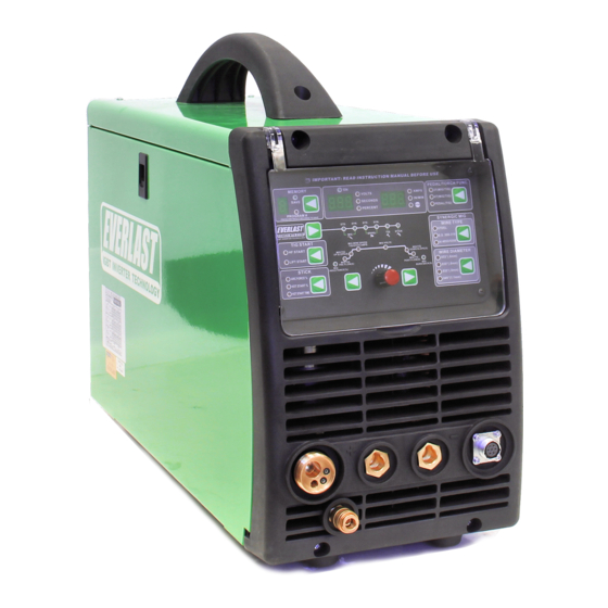
EVERLAST
POWER MTS 221STi
A Digitally-Controlled, Multi-Process MIG/AC-DC TIG/Stick Welder
CC
CV
GMAW
SMAW
GTAW
IGBT
AC/DC
PULSE
Operator's Manual for the PowerMTS 221STi
Safety, Setup and General Use Guide
everlastwelders.com
1-877-755-9353
329 Littlefield Ave. South San Francisco, CA 94080 USA
Rev. 1
Specifications and Accessories subject to change without notice.
0 10308-18
Advertisement
Table of Contents

Related Manuals for Everlast POWER MTS 221STi


Summary of Contents for Everlast POWER MTS 221STi
- Page 1 EVERLAST POWER MTS 221STi A Digitally-Controlled, Multi-Process MIG/AC-DC TIG/Stick Welder GMAW SMAW GTAW IGBT AC/DC PULSE Operator’s Manual for the PowerMTS 221STi Safety, Setup and General Use Guide Rev. 1 0 10308-18 everlastwelders.com Specifications and Accessories subject to change without notice.
-
Page 2: Table Of Contents
Table of Contents Section……………………………………………….Page Letter to the Customer …………………..………… Everlast Contact Information…………….…………. Safety Precautions…………………………………… Introduction and Specifications…..………………… Overview of Parameters and Specifications……. Technical Parameters……………………………... General Description, Purpose and Features……. Set Up Guide and Component Identification….…... Connections and Polarity…………………………. Installing The Wire Spool…………………………. -
Page 3: Letter To The Customer
It is also important so that we may track your satisfaction with Everlast products and services. If you are unable to register by web- site, contact Everlast directly through the sales department at the main customer service number in your country. -
Page 4: Everlast Contact Information
Serial number: _____________________________ Model number: _____________________________ Date of Purchase:___________________________ Contact Information Everlast US: Everlast consumer satisfaction email: sales@everlastwelders.com Everlast Website: everlastwelders.com Everlast Technical Support: tech@everlastwelders.com, support@everlastwelders.com Everlast Support Forum: http://www.everlastgenerators.com/forums/index.php Main toll free number: 1-877-755 WELD (9353) 9am—5pm PST M-F 11am-4pm PST Sat. -
Page 5: Safety Precautions
Safety Precautions Everlast is dedicated to providing you with the best possible equipment and service to meet the demands of the welding applications that you have. We want to go beyond delivering a satis- factory product to you. That is the reason we offer technical support to assist you with your needs should an occasion occur. - Page 6 Safety Precautions These safety precautions are for protection of your safety and health. Failure to follow these guidelines may result in serious injury or death. Be careful to read and follow all cautions and warnings. Protect yourself and others from danger and injury. Welding and cutting processes produce high levels of ultraviolet (UV) radiation that can cause se- vere skin burn and damage.
- Page 7 Safety Precautions WARNING! Persons with pacemakers should not weld, cut or be in the welding area until they consult with their physician. Some pacemakers are sensitive to EMF radiation and could severely malfunction while welding or while being in the vicinity of someone welding. Serious injury or death may occur! Welding and plasma cutting processes generate electro-magnetic fields and radiation.
- Page 8 Safety Precautions WARNING! Electrical shock can kill. Make sure all electrical equipment is properly grounded. Do not use frayed, cut or otherwise damaged cables and leads. Do not stand, lean or rest on ground clamp. Do not stand in water or damp areas while welding or cutting. Keep work surface dry. Do not use welder or plasma cutter in the rain or in extremely humid conditions.
-
Page 9: Introduction And Specifications
Section 1 Introduction and Specifications Overview of Parameters and Features* Power i-MIG 221STi** MIG/TIG/Stick Amp Range 120V: MIG 30-125A/ TIG DC: 10-125A, AC: 20-150A / Stick 10-120A 240V: MIG 30-200A/ TIG DC: 10-250A, AC: 20-250A / Stick 10-200A Volt Adjustment Range MIG 120V: 15.5-21V 240V: 15.5-26V MIG Wire Feed Speed... -
Page 10: Technical Parameters
Section 1 Introduction and Specifications EVERLAST POWERMTS 221STi MODEL: PowerMTS 221STi Serial No. EN/ IEC60974.1 120V; DC: 30-150A; 15.5-20.3V 240V; DC: 30-200A; 15.5-26V 100% 100% 125A 100A 200A 160A 130A 20.3V 20.5V 120V; DC: 10-125A; 10.4-15V 240V; DC: 10-200A; 10.4-18V AC: 20A-125A;... -
Page 11: General Description, Purpose And Features
15 series type guns. At this time, Everlast does not ti-process welders of this range of capability, helping it offer a flux core gun or shield for this unit. Howev- retain portability. - Page 12 360A spool gun. Also the user may want to consid- having to trim the wire before restarting the arc. er the Everlast SM200N-MTS gun which is a 200+ 6) Synergic MIG Mode. Synergic mode may be en- Amp gun with a 24 series barrel. A spool gun is an gaged to simplify welder setup and adjustment.
- Page 13 If the error does 1) Do not use the welder in damp or wet areas. Per- not clear after cycling, cease operation and call Everlast spiration and other forms of water in contact with Technical Support.
-
Page 14: Setup Guide And Component Identification
Section 2 Setup Guide and Component Identification CONNECTIONS AND POLARITY REAR ADJUSTMENT VALVE The Ball valve will float briefly once the main cylinder valve is opened and will then settle down and stop floating after 4 to 5 seconds. Fully open the cylinder when in use to prevent valve leaks. - Page 15 If the regulator leaks, while under warranty contact Everlast for a replacement. Warning! Never attempt to repair a leaking regulator yourself. The parts are under pressure. Serious njury or death may occur.
- Page 16 Section 2 Setup Guide and Component Identification CONNECTIONS AND POLARITY STOP! Read the information on this page and the following pages carefully. It contains im- portant information on correct polarity of your torches and guns for all processes. CAUTION! Pay attention to the separate DC and AC TIG con- nections.
- Page 17 Section 2 Setup Guide and Component Identification CONNECTIONS AND POLARITY MIG (GMAW)* WORK *The feeder connection located under the spool cover must be located on the positive terminal. MIG requires that the gun be used with a positive polarity.
- Page 18 Section 2 Setup Guide and Component Identification CONNECTIONS AND POLARITY Flux-Core (F-CAW)* WORK The feeder connection located under the spool cover must be located on the negative terminal. Flux- Core wire requires that the gun be used electrode negative (EN) in most cases. Consult the wire manu- facturer recommendations as the final authority .
- Page 19 Section 2 Setup Guide and Component Identification CONNECTIONS AND POLARITY MIG (GMAW) with Spool Gun* NOTE: This unit cannot be fitted with a push-pull gun. CONTROL WORK *The feeder connection located under the spool cover must be located on the posi- tive terminal.
- Page 20 Improper connection will result in no gas flow or water coming out of the torch head. For an air-cooled torch alternative (all air-cooled torches handle 200 amps or less), contact Everlast for a full range of Everlast and NOVA torches.
- Page 21 Improper connection will result in no gas flow or water coming out of the torch head. For an air-cooled torch alternative (all air-cooled torches handle 200 amps or less), contact Everlast for a full range of Everlast and NOVA torches.
- Page 22 Section 2 Setup Guide and Component Identification CONNECTIONS AND POLARITY Stick (SMAW)* WORK TORCH *This is the typical setup for stick welding. Most all welding electrodes use electrode posi- tive as the preferred polarity. Some will run electrode negative (EN) if needed. Most will not perform well in EN.
-
Page 23: Installing The Wire Spool
Section 2 Setup Guide and component Identification INSTALLING THE WIRE SPOOL To load the spool of wire: Loosen and remove the small threaded tensioning nut on the spool carrier by turning it counter-clockwise. Remove the tensioning spring and outer hub spacer. Slide spool onto the shaft. -
Page 24: Polarity/Gas/Amp Recommendations
Section 2 Setup Guide and Component Identification GENERAL POLARITY RECOMMENDATIONS* Table 1 *Consult the manufacturer of the filler material recommendations concerning polarity . PROCESS TORCH POLARITY WORK POLARITY MIG (GMAW) FLUX CORE (FCAW) STICK (SMAW) TIG (GTAW) + /AC TYPICAL GAS SELECTION AND SETTING GUIDE Table 2 PROCESS MIG (GMAW) STEEL... - Page 25 Section 2 Setup Guide and Component Identification TIG (GTAW) OPERATION GUIDE FOR STEEL (ALUMINUM)* *As a general rule, set amperage using 1 amp for every .001” of metal thickness for aluminum. Less is required for DC. METAL THICKNESS WELDING AMPS TUNGSTEN DIA.
-
Page 26: Front View Middle Panel
Section 2 Setup Guide and Component Identification FRONT VIEW/ CONNECTION PANEL POWER i-MIG 221STi CONTROL OUTLET... -
Page 27: Middle Panel Item Description And Explanation
Section 2 Setup Guide and Component Identification Middle Panel View and Explanation of Connections 5. Gas Connection. This is the gas connection when welding in TIG mode. The quick coupler is 1. Negative Connector. The DINSE 35 Style con- designed to offer quick and efficient coupling of nector is an industry standard sized connector. -
Page 28: Front View/Control Panel
Section 2 Setup Guide and Component Identification FRONT VIEW/CONTROL PANEL POWER i-MIG 221STi... - Page 29 Section 2 Setup Guide and Component Identification Front Panel Description and Explanation of function: will cease and an error code will be generated in the display. Wire feeding may continue if the Stop 1. Volts/Seconds/Percent Display and LEDs. The indicator is on, but welding output will cease. If Volt/Function display works in conjunction with an error code is generated, look up the error code the LEDs directly beside the display.
- Page 30 Section 2 Setup Guide and Component Identification thickness. Instead, the Synergic function auto- (the current carrying capability of a specific wire matically defaults to a minimum Amp setting because of its diameter and metal type) of differ- based off of the combination of wire type and ent available wires, each change of wire diameter wire diameter selected by the user.
- Page 31 Section 2 Setup Guide and Component Identification E6011, more arc force will be needed. Begin at age while welding. You will not be able to ad- 50% and work up to 70% to maintain best arc per- just amps/wire speed on the panel in synergic formance.
- Page 32 Section 2 Setup Guide and Component Identification function in the sequencer chart. Depending restart upslope before end current is reached. upon the process selected, some LED’s will be Setting a long downslope helps improve heat skipped over as the button is pressed. Do not control in 4T as the torch switch is cycled be- let that confuse you as some features are not tween downslope and upslope before the arc is...
- Page 33 Section 2 Setup Guide and Component Identification dition change. This control is primarily useful for good for light gauge metals and offers great con- short circuit welding and has limited value in Axial trol and good bead profile qualities on thin gauge Spray.
- Page 34 Section 2 Setup Guide and Component Identification soften (or increase) the run-in effect. The run in mode, the weld will be much cleaner, with less works similar to MIG hot start and has a similar porosity at both the beginning and the end of the effect, helping to reduce porosity at the beginning weld.
- Page 35 Section 2 Setup Guide and Component Identification low, the weld will appear ropey and cold and the wire may even stub into the puddle. If the volt- age is set too high, undercut may develop at the toes of the weld, or burn though may occur. Voltage is not adjustable in TIG or Stick mode.
-
Page 36: Side View
Section 2 Setup Guide and Component Identification SIDE VIEW POWER MTS 221STi (Note: Image scale is compressed horizontally to fit this format) -
Page 37: Side View Item Description And Explanation
Section 2 Setup Guide and Component Identification Side Description and Explanation: will continue to wrap the wire around the drive 1. Wire Spool Carrier Assembly. Make note of the mechanism or will jam wire inside the gun liner correct assembly order if disassembled. The or- until the trigger is released. -
Page 38: Rear View Back Panel
Section 2 Setup Guide and Component Identification REAR VIEW/BACK PANEL POWERMTS 221STi 1x220V... -
Page 39: Control Panel Item Description And Explanation
“clean power” and provide less than 5% THD. Consult your generator manufacturer for information regarding the clean power rating on specific units. Everlast does not pro- vide a list of approved generators. Manufactur- ers rate their units as clean power independent- ly according to industry standards. -
Page 40: Basic Theory And Function
Basic Theory and Function Section 3 MIG OPERATION General Setup of Amps and Volts. culator recommendations is that most people find When welding in standard with the PowerMTS 252S- them either too hot or too cold. For some people, it Ti, the two main functions that require adjustment may not even close. - Page 41 Section 3 MIG OPERATION metals without having to step down a size in While Everlast uses the term “arc force”, it is known wire. While ultimately there are limits to what by many different terms. Often it is referred to as any given wire can weld on the lower end of it’s...
- Page 42 Basic Theory and Function Section 3 BASIC MIG OPERATION time the that the arc remains on after the trigger is wire stick-out and creating an irregular start and a released. porous weld. If the burn back control is set too long it can cause The end of the wire should be positioned just barely the wire to burn back into the tip itself and welding above the metal when the trigger is pulled for the...
- Page 43 Basic Theory and Function Section 3 MIG OPERATION or pull the MIG gun. Stringer beads are often best A MIG wire such as ER70S-6 or ER70S-2 includes a for novice welders. Stringers are simply straight sufficient level of deoxidizers such as silicone and beads that move forward with little or no side to copper that are formulated to allow it to handle mi- side travel or oscillation.
- Page 44 Basic Theory and Function Section 3 MIG OPERATION where porosity and inclusions can be introduced.
-
Page 45: Mig Operation (Diagrams)
Basic Theory and Function Section 3 MIG OPERATION Besides a butt joint and lap joint which are often used V-GROOVE (60-80°) DOUBLE V-GROOVE for thinner metal gauges, consider using one of these groove joints for best welding results. When grinding or cutting the bevels, especially with a single V- groove, it may be beneficial to leave a small land with U-GROOVE... - Page 46 Basic Theory and Function Section 3 MIG OPERATION Problem: Gun is not being held vertical from side to side. Wire is not being directed to the center of the puddle. This concentrates heat on one side of the joint and results in poor fusion on the neglected side.
- Page 47 Section 3 Basic Theory and Function MIG OPERATION Characteristics: Concave weld, poor filling, possi- ble undercutting resulting in weak weld. Possible Causes: Voltage too high, not enough wire speed, too short of wire stick out, wrong gun angle. Remedy: Decrease voltage, use push motion, in- crease wire speed.
-
Page 48: Special Notes Concerning Operation
Basic Theory and Function Section 3 Special Notes Concerning Operation. more CO2 is added, the rust resistance of stainless goes down due to the added car- 1. Shielding Gas Selection for MIG and TIG. bon content. Ideally, there are several Tri- While welding aluminum with the Spool gas mixes out there that are well suited to gun or MIG gun you must use 100% Ar-... - Page 49 Everlast for your unit. For the best match- control. In TIG mode you are controlling up, we recommend the Parker Pre-Flow, Post-Flow, Up and Downslope of 4.
- Page 50 Basic Theory and Function Section 3 user must choose between the two. There is no other operation style similar to a foot pedal for MIG. The “T” refers to the number of “travels” of the remote switch required to operate the programming of the sequencer.
-
Page 51: Stick Operation
Basic Theory and Function Section 3 STICK OPERATION STARTING METHODS Tapping Method Scratch/Match Method Striking the Arc Make sure the unit is turned on and the startup cycle has finished. Select the Stick icon on the Process Selector. Make sure the electrode holder is in the Positive connector and the work clamp is in the negative connector. Select the Amp level desired. -
Page 52: Basic Tig Operation
Basic Theory and Function Section 3 Basic TIG Operation Welding. If you are new to TIG welding, it’s General Setup. The process to set up the important that you understand that TIG weld- welder for the basic TIG mode is much less in- ing is much slower than MIG or Stick welding. - Page 53 Basic Theory and Function Section 3 Basic TIG Operation middle finger grasp the rod with the thumb forms. If you need, count as you time your propelling it forward. Other rod manipulation dips until you can do it without thinking. As variations may be used, but the key is to devel- you proceed to dip your rod into the edge of op a comfortable, natural movement that is...
-
Page 54: Tig Arc Starting
Basic Theory and Function Section 3 Note: A TIG lift start should use a nearly seamless motion. Use a light touch and a quick motion for best results. LIFT START OPERATION <1/8” Position the edge of the ceramic cup on the metal. Press and hold the torch switch or press the foot pedal. Wait for the Pre-flow to start. -
Page 55: Tungsten Preparation
Basic Theory and Function Section 3 TUNGSTEN PREPARATION 1. Use a dedicated grinding wheel or contamination may re- sult. Do not breath grinding dust! Wear eye protection and gloves. 2. Grip the Tungsten firmly. 3. Grind the Tungsten perpendic- ular to the wheel face. -
Page 56: Pulse Tig Operation
Basic Theory and Function Section 3 Pulse TIG Operation EXAMPLE 1 TIG Pulse. The TIG pulse creates two amp Peak Pulse Amps: 100 amps, values, a high and a low value that cycle back Base Amps: 50% and forth between each other while welding. Pulse Time On: 50% The upper amperage is called the “TIG Pulse AMPS... - Page 57 Basic Theory and Function Section 3 Pulse TIG Operation time-on will increase the duration the Peak Amp stage of the cycle which in turn will increase the heat and will increase penetration. Pulse Balance is also known in the industry as duty cycle. For welding purposes the term “Pulse Time On”...
-
Page 58: Ac Tig Operation
While it is certain that others in the industry fast freezing puddle is desired, particularly will follow Everlast’s first to market model, on thin aluminum. Total heat output is none will likely be as simple and convenient affected regardless of an amperage. - Page 59 Basic Theory and Function Section 3 AC TIG Operation reduced and over-cleaning results in wide nating polarity between electrode negative etch lines running parallel to the side of the and electrode positive, creating something weld. Not all welds conditions will be alike that resembles a wave when viewed on an so more cleaning is required at times than oscilloscope.
- Page 60 Basic Theory and Function Section 3 AC TIG Operation Cleaning/Frosted Area of Aluminum NOTE: 1. Due to the rapid switching of the inverter, High Frequen- 30% EP cy (HF) is not needed except to start the arc. The HF TIG only Narrow bead/etching/sharp tungsten refers to the initial arc start, and can be used for DC as well.
-
Page 61: Tig Work Sheets
Basic Theory and Function Section 3 TIG OPERATION TIG Work Sheet 1 Steel Grade_______ Metal Tungsten Filler Gas Flow Welding Peak Amps Base Amps % Pulse Frequency Pulse Time-On% PGM # Thickness Size/Type Diameter Rate/Type Amps (If Applicable) (If Applicable) (If Applicable) (If Applicable) NOTES:... - Page 62 Basic Theory and Function Section 3 TIG OPERATION TIG Work Sheet 2 Stainless Steel Grade_______ Metal Tungsten Filler Gas Flow Welding Peak Amps Base Amps % Pulse Frequency Pulse Time-On% PGM # Thickness Size/Type Diameter Rate/Type Amps (If Applicable) (If Applicable) (If Applicable) (If Applicable) NOTES:...
- Page 63 Basic Theory and Function Section 3 TIG OPERATION TIG Work Sheet 2 Aluminum Grade_______ Metal Tungsten Filler Gas Flow Welding Pulse Pulse Pulse Pulse PGM # Thickness Size/Type Diameter Rate/Type Amps Freq. Balance Peak Amps Base Amps % Frequency Hz Time-On% (If Applicable) (If Applicable)
-
Page 64: 15 Series Mig Torch
15 Series. The Innotec® listed above is currently the default supplier of the 15 series. Everlast is not the torch manufacturer, but equips the PowerMTS unit with some of the most prov- en torches in history. Numerous manufacturers all over the world make and use interchangeable variations of these torches including Binzel and Trafimet. -
Page 65: Series Consumables
Basic Theory and Function Section 3 NOTE: Over time, pressure on the drive rolls causes metal fragments from the filler wire’s surface to find its way to the gun cable liner. If the wire guide is not cleaned, it can gradually clog up and causes wire feed mal- functions. -
Page 66: Series Mig Torch
Basic Theory and Function Section 3 24 SERIES MIG TORCH (OPT) Expanded View... -
Page 67: Series Consumables
Euro connector as an option. This list is provided as a general cross reference and does not guar- antee that every variation or type is directly available from Everlast. In the left column, are the OEM part numbers. Trafimet ® and Binzel®... -
Page 68: 26/18 Series Tig Torch
Basic Theory and Function Section 3 EXPANDED VIEW OF TIG TORCH (Actual appearance may vary slightly from what is listed.) 5/8” TYPICAL PARTS FOR 26/18 Series Torch ( STYLE MAY VARY) QTY. Long Back Cap with O-Ring Short Back Cap Opt. - Page 69 Wire continues feeding but no large diameter wires. Check power plug for problems. arc is present. If easily tripped the Resistor value too low. (Contact Everlast if OC is tripping regularly with normal settings.) Potentiometer damaged. Repair or Replace it. Welding Voltage/Current is uncon- trollable Control board damaged.
-
Page 70: Troubleshooting Guide
Solenoid is for higher flow of gas. Listen for audible click of gas sticking. Too short of pre-flow or solenoid. If no click is heard, then contact Everlast post-flow Support. Clean weld properly. Increase pre flow or post flow. -
Page 71: Error Codes
Troubleshooting Guide Section 4 Error Codes Error Code Meaning Possible Cause Over Voltage/Under Voltage Check Power Source, Correct Wiring. Over Current Operating machine on too small of a conductor. Internal machine fault Over Temperature Duty Cycle exceeded. Blocked cooling. Fans not operating properly. Stuck Switch Gun switch is held too long without at- tempting to strike an arc.
Need help?
Do you have a question about the POWER MTS 221STi and is the answer not in the manual?
Questions and answers