Table of Contents
Advertisement
Quick Links
Publish Date: 3-30-2022
EVCYCLONE212 Rev. 1
USA/North America
©Everlast Power Equipment
DC
230A
DC
160A
120/240V
Welders, Plasma Cutters, Multi-Process
Safety, Setup and General Use Guide For The
Operator's Manual
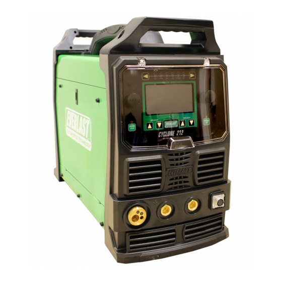
Cyclone 212
FUNCTION: MIG/Stick Welder
PURCHASE DATE:
MODEL NAME:
SERIAL NUMBER:
OPTIONAL ACCESSORY SERIAL NUMBER:
Advertisement
Table of Contents

Subscribe to Our Youtube Channel
Related Manuals for Everlast Cyclone 212


Summary of Contents for Everlast Cyclone 212
- Page 1 Publish Date: 3-30-2022 EVCYCLONE212 Rev. 1 USA/North America ©Everlast Power Equipment 230A Safety, Setup and General Use Guide For The Cyclone 212 160A FUNCTION: MIG/Stick Welder PURCHASE DATE: MODEL NAME: SERIAL NUMBER: OPTIONAL ACCESSORY SERIAL NUMBER: Operator’s Manual 120/240V Welders, Plasma Cutters, Multi-Process...
-
Page 2: Table Of Contents
TABLE OF CONTENTS SPECIAL NOTICE AND CALIFORNIA PROPOSITION 65 WARNING CUSTOMER GREETING AND EXPLANATION OF PROCEDURES WARRANTY AND CONTACT INFORMATION SAFETY DISCLAIMER AND HF WARNING SAFETY WARNINGS, DANGERS, CAUTIONS AND INSTRUCTIONS GENERATOR OPERATION INFORMATION SPECIFICATIONS DUTY CYCLE INFORMATION BREAKER AND WIRING REQUIREMENT INFORMATION GETTING STARTED, UNPACKING YOUR UNIT AND INSPECTION CONNECTING YOUR UNIT TO THE POWER SOURCE AND WIRING INFORMATION SHIELDING GAS CONNECTION AND SELECTION... -
Page 3: Special Notice And California Proposition 65 Warning
Due to multiple variables that exist in the welding field and the changing nature of it and of the Everlast product line, Everlast Power Equipment INC. does not guarantee the accuracy, completeness,... -
Page 4: Customer Greeting And Explanation Of Procedures
Many issues can be resolved over the phone. If the issue cannot be resolved over the phone/email, you may be given an op- tion to return the unit, or have a part shipped to you, at Everlast’s discretion. Keep in mind, you may be asked questions that seem basic, or ele- mentary to your knowledge base. -
Page 5: Warranty And Contact Information
Warranties and service policies and procedures vary from country to country and are maintained and supported by the region- al or in country distributor of Everlast welding equipment. USA Customers Only: For full details on the 5 year parts and labor warranty, 30 day satisfaction policy, terms of sale, and how to proceed with a war- ranty claim, please visit: https://www.everlastgenerators.com/standard-warranty. -
Page 6: Safety Disclaimer And Hf Warning
Safe operation and proper maintenance is your responsibility. Everlast is dedicated to keeping safety a top priority. While we have compiled this operator’s manual to instruct you in basic safe operation and maintenance of your Everlast product, it is no substitute for observing safe welding practices and behavior. Safe welding and related cutting operations require basic knowledge, experience and ultimately the exercise of common sense. -
Page 7: Safety Warnings, Dangers, Cautions And Instructions
It is your responsibility to make certain that the use of this welder is restricted to per- sons who have read, understand and follow the warnings and instructions in this manual. If you or the operator needs further instruction, contact Everlast welding support at 1-877 755 -9353 ext. 204 or seek qualified professional advice and training. - Page 8 Safety Warnings, Dangers, Cautions and Instructions DANGER! Welding and cutting operations pose serious inhalation hazards. Some of these hazards are immediate while others are cumulative in their effect. Do not weld in enclosed spaces or in areas without adequate ventilation. Fumes and gases released in the welding and cutting operations can be toxic.
- Page 9 Safety Warnings, Dangers, Cautions and Instructions CAUTION! Trip Hazards exist around this unit. Cords, cables, welding leads and hoses pose a trip hazard. Be aware of their location and inform others of their location. Tape and secure them so they will stay out of high traffic areas. CAUTION! Welded metal can stay hot long after welding is completed.
-
Page 10: Generator Operation Information
REAR OUTLET WARNING! If equipped, never use the electrical power outlet on the back of this machine for anything other than powering an Everlast brand water cooler. This is a special outlet designed to produce 240V with limited amperage draw. No other device or brand should be used in con- junction with this unit’s outlet. -
Page 11: Specifications
Specifications Duty Cycle Duty Cycle is simply the amount of time out of a 10 minute period in which the unit can operate. For example, if this unit has a duty cycle of 15% at maximum output means that the unit can be operated for 1.5 minutes out of 10 minutes. This means the unit may be operated be continuously, or intermittently for 1.5 minutes during the 10 minute period of time while the machine is MIG welding at maximum output. -
Page 12: Breaker And Wiring Requirement Information
Use the I1MAX and the I1EFF ratings listed above to determine the proper breaker and con- ductor (wire) sizing required. Everlast welders are designed around use in industrial wiring applications and are intended to be used with modern elec- trical systems. - Page 13 National Electric Code (NEC) and local codes. If needed, refer the electrician to Article 630 of the NEC during consultation to determine proper application and wiring needs. Use the I1MAX and the I1EFF ratings listed above to determine the proper breaker and conductor (wire) sizing required. Everlast welders are designed around use in industrial wiring applications and are intended to be used with modern electrical systems.
-
Page 14: Getting Started, Unpacking Your Unit And Inspection
Other drive roll sizes and types should be purchased direct from Everlast. The included drive roll is a V groove drive roll, de- signed for solid steel wire .035” and .030” wire. For flux core or aluminum use, you must purchase the correct type for proper wire feeding. -
Page 15: Connecting Your Unit To The Power Source And Wiring Information
Do not wire connections for this machine if you are not (the conductors and ground) are black, white and green. A red wire, qualified. Everlast is in no way liable for any damages caused by im- which is traditionally used as a “hot” leg (power conducting wire) of power is not present in a three-wire 240V wire circuit of a welder. -
Page 16: Shielding Gas Connection And Selection
Connect the regulator tubing to the regulator. The regulator may be The Cyclone 212 is a synergic unit which incorporates the type of supplied with a hose barb connection, or a threaded connection for gas and metal wire being welded with as a base to make accurate the tubing (depending upon region). -
Page 17: Selecting Polarity And Installing Torches
Setup Guide Getting Started The on screen programming will remind you what polarity to use, but machine. Failure to change polarity will result in erratic operation, bird’s in case you forget, refer to the illustrations below. nesting of the wire, poor fusion and excess spatter. Use illustrations below as a guide. - Page 18 Getting Started SELECT THE CORRECT STICK POLARITY. INSTALLING THE OPTIONAL SPOOL GUN. The Everlast SM200N-MTS Spoolgun is recommended for use with Where Do I Connect The Stick Torch? this unit and provides the best duty cycle and amperage rating. Electrode...
-
Page 19: Installing The Mig Wire And Spool Gun Connection
Setup Guide Getting Started CHECK AND CHANGE YOUR DRIVE ROLL. INSTALL THE WIRE AND FEED THE GUN. The unit comes equipped with .030” and .035” drive rolls. NOTICE: Once the wire spool has been installed, flip the tensioner lever down For most purposes up to 3/16”... - Page 20 Setup Guide Getting Started • Adjust the wire until the stuttering or jerking disappears. TRIM THE WIRE AFTER INSTALLATION. Trim the wire sticking out of the nozzle to 1/4” to 3/8” (6mm to 9mm) • Do not over-tighten the tensioner or use more tension than in length with wire cutters.
-
Page 21: Front Panel View And Component Id
Component Identification and Explanation Front Panel View Number Component Identification Component Note Protective Cover Keep cover down and in place during welding activities and in storage. Euro-Style Quick Connector Connect this to the MIG gun or Spool Gun. Positive Terminal (+) For Stick, connect to the Torch. -
Page 22: Rear Panel View And Component Id
This switch doubles as the main power switch and disconnect switch. If this switch trips and the welder power turns off, a significant internal event or failure of the switch may have occurred. If this occurs, immediately remove from service and mark/tag according to regulations and contact Everlast Tech Sup- port for further diagnosis and/or repair options. -
Page 23: Control Panel Layout
The left adjustment knob is used change the desired status of a function (i.e. voltage, turn on/off, electrode type, thickness Left Adjustment etc.) and to set all adjustable values to the left side of the black dividing hash mark just above the “EVERLAST” logo. If you Knob push in on the knob while adjusting, it will adjust in larger increments, usually in whole numbers or increments of 10. -
Page 24: Getting Ready To Weld
Contact Selection), and parameters (items that change in value in a range Everlast technical support if this does not agree. such as inductance percent) are selectable with the arrow buttons. -
Page 25: Setting Up The Unit For Welding Manually
Component Identification and Explanation Setting the Unit Up For Welding Manually process. Be sure to wait until this screen is present before you at- THE WELCOME SCREEN tempt any change of the welding process. Any time you change pro- When you first turn the unit on with the rear power switch, this screen cesses, the screen will reappear briefly to remind you to make any will greet you as the machine begins the boot process. - Page 26 Component Identification and Explanation Setting the Unit Up For Welding Manually ed setting will default back to the Voltage. highlight (turn green) the Spot Timer. Use the right side adjust- ment knob to turn the Spot Timer on and set the duration of the Pre-Flow.
- Page 27 Component Identification and Explanation Setting the Unit Up For Welding Manually Voltage Input Confirmation. This confirms which voltage the machine is being supplied. This also serves as a diagnostic tool. If the machine shows 120V, while operating on 240V, then the power supply to the welder is likely faulty.
-
Page 28: Setting Up The Powerset Mode
Component Identification and Explanation Setting the Unit Up PowerSet Mode use of PowerSet.) Once activated you will be ready to begin entering UNDERSTANDING POWERSET. the information you need. The PowerSet mode, regardless of process selected is designed to help the user make accurate settings without the aid of complicated charts or calculators. - Page 29 Component Identification and Explanation Setting the Unit Up PowerSet Mode you are increasing or decreasing the value). If you move further than is recommended, the bar and numbered value (4) will turn red. If you find that you have moved too far off the suggest setting of the machine, all you will need to do is turn the adjustment knob until you are back at the center, tallest bar.
-
Page 30: Explanation Of Mig Functions And Terms
Component Identification and Explanation EXPLANATION OF MIG FUNCTIONS AND TERMS EXPLANATION OF WELDER FUNCTIONS specific parameters for Volt and Amp settings for each wire diameter and class of wire. The ranges of volt and amp parameters generally varies somewhat from brand to brand, so be sure to read the packaging and/or manufacturer literature to determine what range of settings are recom- Volt and Amp Settings mended. - Page 31 Component Identification and Explanation EXPLANATION OF MIG FUNCTIONS AND TERMS too long of wire stick out. age heat build up. For example: when welding vertically weaves are al- most always used to prevent the molten metal from sagging due to the force of gravity.
- Page 32 Component Identification and Explanation EXPLANATION OF MIG FUNCTIONS AND TERMS multiple smaller passes to complete a plate weld for a higher quality result. Joint Preparation For best results, this requires that most joints 1/4” and over be prepared with a grinder to accept multiple weld passes. The weldment edges should be ground to form a V, U or J shaped groove to create a recess V-GROOVE (60-80°) DOUBLE V-GROOVE...
- Page 33 Component Identification and Explanation EXPLANATION OF MIG FUNCTIONS AND TERMS MIG Welding is fairly simple if you keep travel angle and direction in mind when welding. See below. If you are welding flux- core, the gun direction is reversed. Remember: If it has gas, you use a push angle. If it is gas-less you use a drag angle. The old welder’s saying “If it has slag, you drag.”...
-
Page 34: Mig Torch Component Breakdown
Component Identification and Explanation INNOTEC 15 SERIES MIG TORCH PARTS BREAKDOWN (MB15AK Style) -
Page 35: Stick Welding Information
Component Identification and Explanation STICK WELDING INFORMATION STICK ARC STARTING METHODS Make sure the unit is turned on and the boot cycle has finished. Select the Stick Process on the Selector. Make sure the electrode holder is in the Positive connector and the work clamp is in the negative connector. Select the Amp level desired. - Page 36 Component Identification and Explanation STICK WELDING INFORMATION HELPFUL HINT: IMPORTANT! This unit is designed for operation with E6011 (E6010 not recommended). Pay particular attention to the Arc Force setting as it affects the ag- To get themaiximum performance and use with these rods, the PowerSet gressiveness of the arc and the amp response.
-
Page 37: Troubleshooting Error Codes
Occasionally a warning screen may pop up and interrupt welding. Pay attention to the code and follow the directions. In most cases it will explain the problem and cause. If the condition cannot be resolved, contact Everlast Tech Support for further help and diagnosis. - Page 38 Check gas flow. Adjust for higher flow of gas. Listen for audible click Weld is dirty/oxidized, or porous. Solenoid is sticking. of gas solenoid. If no click is heard, then contact Everlast Support. Clean weld properly. Increase pre flow or post flow. For Flux Core, a certain amount of spatter, haxe and smoke is common.
Need help?
Do you have a question about the Cyclone 212 and is the answer not in the manual?
Questions and answers