
Related Manuals for Advantech RSB-4220


Summary of Contents for Advantech RSB-4220
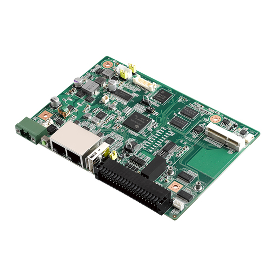
- Page 1 User Manual RSB-4220 3.5” SBC with TI Sitara AM3352 Cortex A8 Single core 1GHz high performance processor...
- Page 2 No part of this manual may be reproduced, copied, translated or transmitted in any form or by any means without the prior written permission of Advantech Co., Ltd. Information provided in this manual is intended to be accurate and reliable. How- ever, Advantech Co., Ltd.
-
Page 3: Declaration Of Conformity
TERMINAL BLOCK 20x2P 2.54 mm 180D 0156-1A40 Ordering Information Model Number Description RSB-4220CS-MCA1E RSB-4220 TI AM3352 1GHz, 512 MB DDR3 RSB-4220WS-MCA1E RSB-4220 TI AM3352 1Ghz 512 MB DDR3 for wide temperature RSB-DK4220-F0A1E RSB-4220 TI AM3352 1Ghz 512MB DDR3 for EVK RSB-4220 User Manual... -
Page 4: Optional Accessories
LVDS cable 1700022248-02 M CABLE USB-A(M)/USB-A(M) 15CM AMK-V006E 1700023307-01 A cable DC JACK/Plug-in 1*2P-5.0 10cm RSB-4220 Certification and Safety Instructions This device complies with the requirements in part 15 of the FCC rules: Operation is subject to the following two conditions:... -
Page 5: Table Of Contents
Board Dimensions............... 21 Figure 2.15Board Dimension Layout (Top Side) ......21 Figure 2.16Board Dimension Layout (Bottom Side) ....21 Figure 2.17Board Dimension Layout (Coastline)......22 Quick Start of RSB-4220................. 22 2.4.1 Debug Port Connection............... 22 2.4.2 Debug Port Setting..............22 Figure 2.18HyperTerminal Settings for Terminal Setup ..... - Page 6 Demo program source code ............57 Chapter System Recovery ......61 System Recovery..................62 Chapter Advantech Services......63 RISC Design-in Services ................ 64 Contact Information................. 66 Global Service Policy ................67 5.3.1 Warranty Policy................67 5.3.2 Repair Process ................68 RSB-4220 User Manual...
-
Page 7: Chapter 1 General Introduction
Chapter General Introduction This chapter gives background information on the RSB-4220 Sections include: Introduction Specifications Environment Specifications Block Diagram... -
Page 8: Introduction
Introduction RSB-4220 is a 3.5” SBC (Single Board Computer) with TI Sitara AM3352 Cortex A8 1GHz processor. The RSB-4220 can support 512MB DDR3 and 4 GB eMMC onboard flash, LVDS , 5 UARTs , 1 USB2.0 Client ,2 GbE , 1SD and Mini PCI-e. The... -
Page 9: Mechanical Specifications
RGMII1 RJ45 UART1 MAX3243 RJ45 RTL8211E RGMII2 UART0 TI Sitara AM3352 1GHz UART2 MAX3243 MINI-PCIE SOCKET USB1 UART3 USB Host/OTG USB0 UART4 MAX3243 UART5 SD SOCKET 4bit SDIO I2C0 PCA9538 GPIO 4MB NOR FLASH SPI0 CAN0 SN65HVD232 RSB-4220 User Manual... - Page 10 RSB-4220 User Manual...
-
Page 11: Chapter 2 H/W Installation
Chapter H/W Installation This chapter introduces the startup procedures of the RSB- 4220 hardware, including jumper setting and device integration. It also introduces the setting of switches, indicators and also shows the mechanical drawings. Be sure to read all safety precau- tions before you begin installation procedure. -
Page 12: Jumpers
Generally, you simply need a standard cable to make most connections. Warning! To avoid damaging the computer, always turn off the power supply before setting jumpers. 2.1.2 Jumper List Table 2.1: Jumper List Boot device LVDS Power Backlight Power USB Host/OTG UART1 RS232, RS422, RS485 select RSB-4220 User Manual... -
Page 13: Jumper Settings
1653003100 Footprint HD_3x1P_100_D Description PIN HEADER 3x1P 2.54mm 180D(M) DIP 205-1x3GS Setting Function (1-2) +3.3V (2-3) LVDS Backlight Power Part Number 1653003100 Footprint HD_3x1P_100_D Description PIN HEADER 3x1P 2.54mm 180D(M) DIP 205-1x3GS Setting Function (1-2) (2-3) +V12 RSB-4220 User Manual... - Page 14 PIN HEADER 3x1P 2.54mm 180D(M) DIP 205-1x3GS Setting Function (1-2) USB Host (2-3) USB OTG Device UART1 RS232, RS422, RS485 select Part number 1600000084 Footprint SW_4x2P_50_260x220 Description DIP SW CHS-02TB(29) SMD 4P SPST P=1.27mm W=5.4mm Setting Function (1-1-1-0) RS232 (0-0-1-0) RS422 (0-1-0-0) RS485 RSB-4220 User Manual...
-
Page 15: Connectors
RSB-4220 supports a lithium 3V/210mAH CR2032 battery with wire via battery con- nector. 2.2.2.2 MiniPCIe (CN2) RSB-4220 supports full size MiniPCIe slot USB interface. If the WiFi card is only half- sized, please purchase extending bracket (P/N: 1960047454N000) for WiFi card fix- ing. Signal Name Signal Name +3.3V... -
Page 16: Figure 2.1 Minipcie
USB_D+ +3.3V +3.3V LED_WWAN# LED_WLAN# Reserved LED_WPAN# Reserved +1V5_IO Reserved Reserved +3.3V Figure 2.1 miniPCIE RSB-4220 User Manual... -
Page 17: Figure 2.2 Debug Port
2.2.2.3 UART0 Debug Port (CN5) RSB-4220 can communicate with a host server (Windows or Linux) by using serial cables. Description +V3.3 DEBUG_TXD DEBUG_RXD Figure 2.2 Debug Port 2.2.2.4 USB Type A Connector (CN12) RSB-4220 has one standard USB2.0 Type A connector in the coastline. The customer can select using USB Host or OTG device by jumper setting. -
Page 18: Figure 2.4 Jtag Pin Header
2.2.2.5 JTAG (CN26) JTAG is reserved for R&D used. Description JTAG_TMS JTAG_TRSTn JTAG_TDI +3.3V JTAG_TDO RTCK JTAG_EMU0 JTAG_EMU1 EMU_RSTn JTAG_EMU2 JTAG_EMU3 JTAG_EMU4 Figure 2.4 JTAG Pin header RSB-4220 User Manual... - Page 19 2.2.2.6 Ethernet Connector (CN36) RSB-4220 provides two RJ45 LAN interface connector, which are fully compliant with IEEE 802.3u 10/100/1000 Base-T CSMA/CD standards. The Ethernet ports provide standard RJ-45 jack connector with LED indicators on the front side to show Active/ Link status and Speed status.
-
Page 20: Figure 2.5 Ethernet Connector
Figure 2.5 Ethernet Connector RSB-4220 User Manual... -
Page 21: Figure 2.6 Dc Power Jack
RSB-4220 comes with a DC-Jack header that carries 9-30V DC external power input. Description DC_IN Figure 2.6 DC power Jack 2.2.2.8 Reset Button (SW3) RSB-4220 has a reset button on the front side. Press this button to activate the hard- ware reset function. Description RESET Figure 2.7 Reset button RSB-4220 User Manual... -
Page 22: Figure 2.8 Sd Slot
2.2.2.9 SD Slot (SD1) RSB-4220 supports SD/MMC card in Class2, 4, 6, 8, 10. Supported capacity is up to 4G (SDHC). Signal Name DAT3 +3.3V DAT0 DAT1 DAT2 Figure 2.8 SD Slot RSB-4220 User Manual... -
Page 23: Figure 2.9 Lvds Connector
2.2.2.10 LVDS Connector (CN32) RSB-4220 provides a LVDS 10x2-pin board-to-board connector for single channel 18 bit LVDS panel up to 1366x768. Please also refer to jumper setting in page 16 before connecting LVDS panel. Description LVDS0_z_D0+ SCL_LVDS0 LVDS0_z_D0- SDA_LVDS0 LVDS0_z_D1+... -
Page 24: Figure 2.10Lvds Inverter Power Connector
Figure 2.10 LVDS Inverter Power Connector 2.2.2.12 2X20 pin Connector (CN28) RSB-4220 provides a 2X20 pin connector, which contains 5 2-wire UART with TX/ RX, 4-wire UART Supporting RS232 RS422 RS485, one 5V CAN, one I2C bus and 4 GPI/GPO w/isolation. -
Page 25: Figure 2.112X20 Pin Connector
COM5_TX COM1_RXD COM5_RX 422-485_TXD+ CAN1_D+ 422-485_TXD- CAN1_D- COM2_RX COM0_TX COM2_TX COM0_RX COM4_TX COM3_TX COM4_RX COM3_RX Figure 2.11 2X20 pin Connector RSB-4220 User Manual... -
Page 26: Mechanical
Jumper for USB host/OTG Debug Port DC_IN Reset LAN1 LAN0 USB 2 x 20 Pin Connector Figure 2.12 Jumper and Connector Layout (Top side) SD Card Figure 2.13 Jumpers and Connector Layout (Bottom Side) Figure 2.14 Coastline Layout RSB-4220 User Manual... -
Page 27: Board Dimensions
2.3.2 Board Dimensions 2.3.2.1 Board Drawing Figure 2.15 Board Dimension Layout (Top Side) Figure 2.16 Board Dimension Layout (Bottom Side) RSB-4220 User Manual... -
Page 28: Quick Start Of Rsb-4220
Figure 2-7. After the bootloader is programmed on SD card, insert power adapter connector to DC jack on RSB-4220 to power up the board. The bootloader prompt is dis- played on the terminal screen. Figure 2.18 HyperTerminal Settings for Terminal Setup... -
Page 29: Test Tools
Test Tools All test tools must be verified on RSB-4220, please prepare required test fixtures before verifying each specified I/O. If you have any problem to get the test fixture, please contact your Advantech contact window for help. 2.5.1 eMMC Test Check the space of NAND flash. -
Page 30: Usb Test
USB OTG Test Jump to OTG mode, Use USB Type A- Type A cable to connect the USB-OTG port of RSB-4220 and the USB port of PC. Copy 20MB xx file to RSB-4220 from PC. Check the RSB-4220 xx file size was 20MB. -
Page 31: Spi Test
Copied 4194304 bytes from address 0x00000000 in flash to ./temp-0.img 0000000 0000 0000 0000 0000 0000 0000 0000 0000 0400000 ============================================================ ################## --------------SPI mtdblock0 Write 0 PASS !!! ============================================================ ============================================================ ###################-----------> SPI Test all mtdblock0 PASS !!! ============================================================ ================================================ #### RSB-4220 User Manual... -
Page 32: I2C Test
60: ‐‐ ‐‐ ‐‐ ‐‐ ‐‐ ‐‐ ‐‐ ‐‐ ‐‐ ‐‐ ‐‐ ‐‐ ‐‐ ‐‐ ‐‐ ‐‐ 70: ‐‐ ‐‐ ‐‐ UU ‐‐ ‐‐ ‐‐ ‐‐ =====I2C test Pass!===== 2.5.6 CAN Test Connect one RSB-4220 CAN Port CAN1_D+ /CAN1_D- and GND with another RSB-4220. Run program to transmit data between two RSB-4220 CAN ports. root@am335x‐adv:/unit_tests# ./AutoRun_CAN.sh Sun Sep 14 01:48:57 UTC 2014 interface = can0, family = 29, type = 3, proto = 1... -
Page 33: Gpio Test
2.5.7 GPIO Test Power on RSB-4220 and boot into OS. Short GPI0 to GPO0, GPI1 to GPO1, GPI2 to GPO2, GPI3 to GPO3. Run program to test GPIO read/write. root@am335x‐adv:/unit_tests# ./AutoRun_gpio.sh GPIO200 direction is: GPIO201 direction is: GPIO202 direction is: GPIO203 direction is: GPIO204 direction is: GPIO205 direction is: GPIO206 direction is: GPIO207 direction is: GPIO test PASS! 2.5.8... -
Page 34: Mini-Pcie Wifi Test
Mini-PCIe WIFI Test Connect the wireless WIFI module to CN2,the supported module P/N is EWM- W150H01E. Run program Autorun_wifi.sh. root@am335x-adv:/unit_tests# ./AutoRun_wifi.sh 'advantech for guest' 12345678 ************************************************** Begin Set the Wireless ************************************************** [ 57.934831] cfg80211: Calling CRDA to update world regulatory domain [ 58.071752] cfg80211: World regulatory domain updated:... -
Page 35: Lan Test
2.5.10 LAN Test RSB-4220 sets DHCP as defaul network portocal. 2.5.10.1 eth0 test Connect RSB-4220 eth0 port with a host computer. Config RSB-4220 eth0 IP as 192.168.1.2.meanwhile,config the host computer IP as 192.168.1.1 root@am335x‐adv:~# ifconfig eth0 192.168.1.2 root@am335x‐adv:~# ifconfig eth0 eth0 Link encap:Ethernet HWaddr 78:A5:04:DD:E1:0A inet addr:192.168.1.2 Bcast:192.168.1.255 Mask:255.255.255.0... - Page 36 2.5.10.2 eth1 test Connect RSB-4220 eth1port with a host computer. Config RSB-4220 eth1 IP as 192.168.1.3. root@am335x‐adv:~# ifconfig eth1 192.168.1.3 root@am335x‐adv:~# ifconfig eth1 eth1 Link encap:Ethernet HWaddr 78:A5:04:DD:E1:0C inet addr:192.168.1.3 Bcast:192.168.1.255 Mask:255.255.255.0 UP BROADCAST RUNNING MULTICAST MTU:1500 Metric:1 RX packets:41 errors:0 dropped:0 overruns:0 frame:0 TX packets:0 errors:0 dropped:0 overruns:0 carrier:0 collisions:0 txqueuelen:1000 RX bytes:5035 (4.9 KiB) TX bytes:0 (0.0 B)
-
Page 37: Rs232 Test
2.5.11 RS232 Test There are 6 UART supported by RSB-4220. /dev/ttyo0 is reserved for RSB-4220 debug port (RSB-4220 CN5), the rest UART ports could be applied by user. 2.5.11.1 UART1 to UART5 RS232 test Switching SW8 to set UART1 working at RS232, short TX with RX of UART1 to UART5. - Page 38 RS485 port of ADAM, then connect UART4 port to RS232 port of ADAM, run pro- gram to transmit data between UART1 and UART4. RSB-4220 RS485 can not support auto flow control, it need be controlled by cus- tomer APP.
-
Page 39: Watchdog Timer Test
2.5.12 Watchdog Timer Test RSB-4220 has an external watchdog IC using TI msp430g2202, which will reset sys- tem when exception occurs. Please refer to below flow Diagram. Disable Default “ ” H/W WDT (Before O.S. stage) Enable “ ” H/W WDT Reset timer, OK (In O.S. - Page 40 28/31 max ep, 16384/16384 memory USB Peripheral mode controller at 47401000 using PIO, IRQ 0 musb-hdrc: ConfigData=0xde (UTMI-8, dyn FIFOs, bulk combine, bulk split, HB-ISO Rx, HB-ISO Tx, SoftConn) musb-hdrc: MHDRC RTL version 2.0 musb-hdrc: setup fif RSB-4220 User Manual...
-
Page 41: Software Functionality
Chapter Software Functionality This chapter details the Linux operating system on the RSB- 4220 platform. -
Page 42: Introduction
In this case, we strongly recommend to have Ubuntu 12.04 LTS installed to your host PC before start RSB-4220 evaluation/development. Package Content We would offer you two different kinds of Linux package for RSB-4220. One is pre- built system image for system recovery another is source code package (BSP). 3.2.1 Pre-built System Image You are able to find the pre-built image 4220LIVxxxx_yyyy-mm-dd.tar.gz from RSB-... -
Page 43: Figure 3.1 Source Code Package Structure
This folder contains scripts for configure system and compile “scripts” images automatically. → This folder contains source code owned by Advantech. “source” 3.2.2.1 cross_compiler You can use the cross compiler tool chain to compile the uImage and related applica- tions. -
Page 44: Figure 3.2 Image\Rootfs
→ just for sample test. Figure 3.2 image\rootfs 3.2.2.5 scripts Some scripts provided by Advantech will help you configure system or build the images more quickly. Please check them as follows: – setenv.sh → A script to setup the developing environment quickly. - Page 45 Linux-specific and general UNIX questions. There are also various README files in ./source/ linux-3.2.0-psp04.06.00.11/Docu- mentation, you can find the kernel-specified installations and notes for drivers. You can refer to ./source/ linux-3.2.0-psp04.06.00.11/Documentation/00-INDEX for a list of the purpose of each README/note. RSB-4220 User Manual...
-
Page 46: Set Up Build Environment
All instructions in this guide are based on Ubuntu 12.04 LTS developing environment. Please install the Ubuntu 12.04 LTS at your PC/NB in advance. When you obtain the RSB-4220 Linux source code package, please refer to following instructions to extract to your developing environment: Copy "335XLBVxxxx_yyyy-mm-dd.bin"... -
Page 47: Build Instructions
This section will guide you how to build the u-boot & Linux kernel. 3.4.1 Build u-boot Image Advantech has written a script to build the u-boot quickly. You can build u-boot image by follow below steps: Open "Terminal" on Ubuntu 12.04 LTS.. -
Page 48: Kernel Source Code Modification
Open "Terminal" on Ubuntu 12.04 LTS. $sudo su (Change to “root” authority) Input user password. #cd /root/335XLBVxxxx_yyyy‐mm‐dd/scripts/ #. setenv.sh (To configure the developing environment automatically) #./cfg_kernel.sh am335x_rsb4220_defconfig #./cfg_kernel.sh menuconfig Then you will see a GUI screen (Linux Kernel Configuration) as below: Figure 3.3 Linux Kernel Configuration RSB-4220 User Manual... -
Page 49: Figure 3.4 Selecting Ti Tps65910 Rtc Driver
Instruments S-35390A” on the list. Choose this option then exit and save your configuration. Figure 3.4 Selecting TI TPS65910 RTC Driver Change directory to “source/ linux-3.2.0-psp04.06.00.11/arch/arm/mach- omap2”, edit the “board-rsb4220.h” and “board-advantech.c”. Please add below codes to source/ linux-3.2.0-psp04.06.00.11/arch/arm/mach- mx6/board-rsb4220.h: /* I2C */ static struct i2c_board_info mxc_i2c0_board_info[] __initdata = { I2C_BOARD_INFO("s35390a", 0x30),... -
Page 50: Create A Linux System Boot Media
Check the SD card location, like: /dev/sdb #cd /root/335XLBVxxxx_yyyy‐mm‐dd/scripts #./mksd‐linux.sh /dev/sdb Type “y” (Start to copy files, wait until it shows [Done]) Then insert the Linux system SD card to RSB-4220 SD card slot (SD1), it will boot up with Linux environment. RSB-4220 User Manual... -
Page 51: Boot From Onboard Flash
Then you can boot from onboard flash without SD card. Debug Message RSB-4220 can connect to a host PC (Linux or Windows) by using console cable and debug port adapter. In order to communicate with host PC, serial communication pro- gram such as HyperTerminal, Tera Term or PuTTY is must required. -
Page 52: Linux System Configuration And Use
= { .name = "TFC_S9700RTWV35TR_01B", .width = 800, .height = 480, .hfp = 127, .hbp = 127, .hsw = 2, .vfp = 22, .vbp = 22, .vsw = 1, .pxl_clk = 20000000, .invert_pxl_clk = 0, RSB-4220 User Manual... - Page 53 "run bootargs_defaults;setenv console=${console} bootargs ${bootargs} root=${mmcroot} rootfstype=${mmcrootfstype} ip=${ip_method} lvds_panel=TFC_S9700RTWV35TR_01B" 15’’ panle(INNOLUX_G150XGE_L04): setenv mmcargs "run bootargs_defaults;setenv console=${console} bootargs ${bootargs} root=${mmcroot} rootfstype=${mmcrootfstype} ip=${ip_method} lvds_panel=INNOLUX_G150XGE_L04" 18’’ panle(AUO_G185XW01_V1): setenv mmcargs "run bootargs_defaults;setenv console=${console} bootargs ${bootargs} root=${mmcroot} rootfstype=${mmcrootfstype} ip=${ip_method} lvds_panel=AUO_G185XW01_V1" RSB-4220 User Manual...
-
Page 54: Service Configuration
/tftpboot. You need execute “chmod 777 /tftpboot” on RSB-4220 to let the tftp server work. Then, user can tftp to RSB-4220 by tftp client in host PC. Use command to get and put file like this: hostPC$ tftp TARGET_SYSTEM_IP tftp>get file1... - Page 55 3.8.2.3 ssh server When boot up the RSB-4220, the ssh service is already started by default. You can run the following command on your host PC to login the RSB-4220: hostPC$ sudo ssh -l root TARGET_SYSTEM_IP The service start command is: root@am335x-adv:/ # /etc/init.d/dropbear start...
-
Page 56: Network Configuration
You can get an IP address via dhcp, also you can configure a static IP address for RSB-4220. Click on the "Network Cfg" icon on the screen. Then Advantech NIC Configuration utility will be started. You can do some configuration of NIC. -
Page 57: Date/Time Configuration
3.8.4 Date/Time Configuration* You can use the tool we provide to modify the system time. Click on the "Time Settings" icon on the screen. Then Advantech Date/Time Settings utility will be started. Figure 3.7 Date/Time Settings After the time is adjusted, please click “OK” button, and the date will be saved. Mean- while, the RTC time will be synchronized to the time you just set. -
Page 58: Brightness Control
Figure 3.9 Brightness Control 3.8.7 Serial Tools We have five serial ports, named ttyO1~ttyO5. And we provide a serial test tool to let it easily to validate the serial ports. Figure 3.10 Serial Control RSB-4220 User Manual... -
Page 59: Matrix Gui User's Guide
/etc/init.d/matrix-gui-2.0 start If you want the Matrix to start with the system by default, please run the following command on RSB-4220: advantech# cp /etc/init.d/matrix-gui-2.0 /etc/rc5.d/S97matrix-gui-2.0 When you want to cancel the default startup, just remove the S97matrix-gui-2.0 file. -
Page 60: Screen Rotation For Qt Application
Additional fields were added that are unique for Matrix. Format for each parameter: <Field>=<Value> The fields and values are case sensitive. 3.8.9 Screen Rotation for Qt Application Please export the Environments: export QWS_DISPLAY=Transformed:Rot90 or run directly run : ./exmaple -qws -display "Transformed:Rot270" RSB-4220 User Manual... -
Page 61: Add A Startup Items When Boot
It is intended for use on embedded Linux devices and is used in this capacity in the OpenEmbedded and OpenWrt projects. Advantech Embedded Linux for RSB-4220 has built-in OPKG package manager, with this tool you can install most of the required software online, and manage them, such as uninstall, upgrades and so on. -
Page 62: Development Guide And Reference
# cp helloworld /media/rootfs/tool Note! /media/rootfs is the mounted point of your Linux system SD card. Remove this SD card and insert it to RSB-4220, then open serial console. On RSB-4220 platform, type #root (Login) On RSB-4220 platform, type #cd /tool On RSB-4220 platform, type #./helloworld... -
Page 63: Development Of Gui Programs With Qt Library
Development of GUI Programs with QT Library With the development kit, you can develop a qt-based GUI program. Follow these steps, you can quickly convert your QT Project to a GUI application for RSB-4220: On your host PC, set up QT Build Environment. - Page 64 = WDIOS_ENABLECARD; ioctl( fd, WDIOC_SETOPTIONS, & i_en); Get the current timeout value: /*get the current timeout value the driver used*/ int timeout = 0; ioctl (fd, WDIOC_GETTIMEOUT, &timeout); Please refer to <BSP_PATH>/source/demo/watchdog folder to get more information. RSB-4220 User Manual...
- Page 65 3.9.3.3 GPIO Programming RSB-4220 has 8 gpios. Please refer to <BSP_PATH>/source/demo/gpio Usage: # ./gpio 200 out 1 Note! “200” means gpio0, and so 200-207 corresponds to gpio0-gpio7. “out” means output . “1” is the value set to the corresponding gpio port.
- Page 66 RSB-4220 User Manual...
-
Page 67: System Recovery
Chapter System Recovery This chapter introduces how to recover Linux operating system if it is damaged accidentally. -
Page 68: System Recovery
On RSB-4220 platform, type #root (Login) On RSB-4220 platform, type #cd /mk_inand On RSB-4220 platform, type #./mkinand‐linux.sh /dev/mmcblk1 On RSB-4220 platform, type “y “ (Start to copy files, wait until it shows [Done]) Power off and remove this SD card. RSB-4220 User Manual... -
Page 69: Advantech Services
Chapter Advantech Services This chapter introduces Advan- tech design in serviceability, tech- nical support and warranty policy for RSB-4220. -
Page 70: Risc Design-In Services
Advantech has been involved in the industrial computer industry for many years and found that customers usually have the following questions when implementing modu- lar designs. - Page 71 RISC COM. Design stage When a product moves into the design stage, Advantech will supply a design guide of the carrier board for reference. The carrier board design guide provides pin defini- tions of the COM connector with limitations and recommendations for carrier board design, so customers can have a clear guideline to follow during their carrier board development.
-
Page 72: Contact Information
RISC platforms. As a supportive role, Advantech primarily helps customers solve their problems in the testing process and will give suggestions and tips as well. Through an efficient verifi- cation process backed by our technical support, customers are able to optimize their applications with less fuss. -
Page 73: Global Service Policy
(Dead-on-Arrival). The DOA Cross-Shipment excludes any shipping damage, cus- tomized and/or build-to-order products. For those products which are not DOA, the return fee to an authorized ADVANTECH repair facility will be at the customers' expense. The shipping fee for reconstructive products from ADVANTECH back to customers' sites will be at ADVANTECH's expense. -
Page 74: Repair Process
"Problem Description". Vague entries such as "does not work" and "failure" are not acceptable. If you are uncertain about the cause of the problem, please contact ADVANTECH's Application Engineers (AE). They may be able to find a solution that does not require sending the product for repair. - Page 75 Product updates and tests upon the request of customers who are without war- ranty. If a product has been repaired by ADVANTECH, and within three months after such a repair the product requires another repair for the same problem, ADVANTECH will do this repair free of charge.
- Page 76 5.3.2.6 Shipping Back to Customer The forwarding company for RMA returns from ADVANTECH to customers is selected by ADVANTECH. Per customer requirement, other express services can be adopted, such as UPS, FedEx and etc. The customer must bear the extra costs of such alternative shipment.
- Page 77 RSB-4220 User Manual...
- Page 78 No part of this publication may be reproduced in any form or by any means, electronic, photocopying, recording or otherwise, without prior written permis- sion of the publisher. All brand and product names are trademarks or registered trademarks of their respective companies. © Advantech Co., Ltd. 2015...
Need help?
Do you have a question about the RSB-4220 and is the answer not in the manual?
Questions and answers