Stryker InTouch FL27 series Maintenance Manual
Critical care bed
Hide thumbs
Also See for InTouch FL27 series:
- Operation manual (496 pages) ,
- Maintenance manual (252 pages) ,
- Operation manual (496 pages)

Subscribe to Our Youtube Channel
Related Manuals for Stryker InTouch FL27 series


Summary of Contents for Stryker InTouch FL27 series
- Page 1 InTouch™ Critical Care Bed Model FL27 (2131/2141) Version 2.4 Maintenance Manual For Parts or Technical Assistance: USA: 1-800-327-0770 (option 2) Canada: 1-888-233-6888 2012/04 C.1 2131-409-002 REV C www.stryker.com...
-
Page 3: Table Of Contents
Touch Screen Removal and Replacement - (Footboard) ........Return To Table of Contents www.stryker.com 2131-409-002 REV C... - Page 4 Standard Siderail Assembly, Head End, Right ..........2131-409-002 REV C www.stryker.com...
- Page 5 Recycling Passports ..............www.stryker.com...
-
Page 6: Symbols
Refer to your local distributor for return and/or collection systems available in your country. Return To Table of Contents 2131-409-002 REV C www.stryker.com... -
Page 7: Introduction
Stryker warrants to the original purchaser that the welds on its Bed products will be free from structural defects for the expected 10 year life of the Bed product as long as the original purchaser owns the products. -
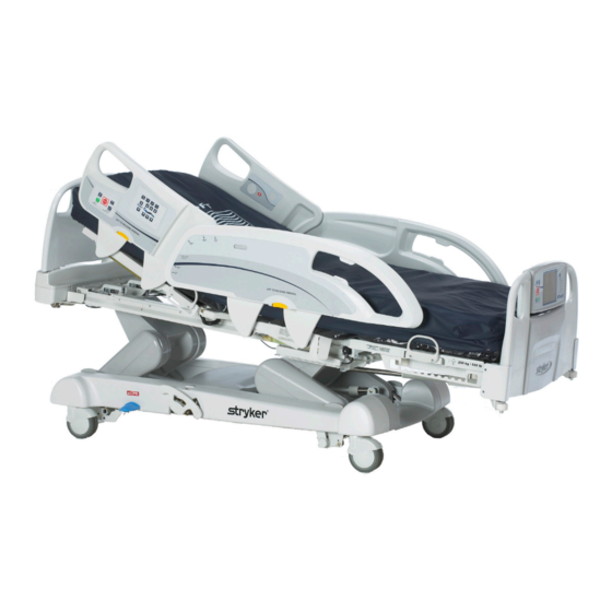
Page 8: Product Illustration
Footboard Control Panel InTouch™ Screen Siderail Release Levers Footboard CPR Emergency Release Pedal Foley Bag Manual ® ZOOM Drive Wheel Casters Hooks Backup (Model 2141 only) (Under base - not shown) Return To Table of Contents 2131-409-002 REV C www.stryker.com... -
Page 9: Specifications
• Fowler 15 seconds • Foot 60 seconds • Seat 30 seconds Drive System Speed (Optional ZOOM Drive) ® • Forward 3.6 mph 5.8 km/h • Backwards 2.5 mph 4.0 km/h Return To Table of Contents www.stryker.com 2131-409-002 REV C... -
Page 10: Warning / Caution / Note Definition
3.0 V 220mAh Lithium Battery, Size 20mm - Varta Int. CR2032 Coin Cell PC Battery Holder, Size 20mm - MDP Int. BA2032 Stryker reserves the right to change specifications without notice. Specifications listed are approximate and may vary slightly from unit to unit or by power supply fluctuations. -
Page 11: Summary Of Safety Precautions
Unplug the bed power cord from the wall when oxygen administering equipment is used. When using a half bed-length tent type, ensure that the siderails are outside the oxygen tent and that the tent does not extend below the mattress support level. Return To Table of Contents www.stryker.com 2131-409-002 REV C... - Page 12 • Because individual beds may have different options, footboards should not be moved from one bed to another. Mixing footboards could result in unpredictable bed operation. • When servicing, use only identical replacement parts provided by Stryker. Note • Throughout this Operations Manual, the words “right” and “left” refer to the right and left sides of a patient lying on his/her back on the bed.
-
Page 13: Optional Zoom ® Drive System (Model 2141)
• Do not modify the InTouch™ Model 2141 bed. Modifying the unit can cause unpredictable operation resulting in injury to the patient or user. Modifying the unit will also void this warranty. Return To Table of Contents www.stryker.com 2131-409-002 REV C... -
Page 14: Static Discharge Precautions
2 and 3 of the following procedure. Do not place unprotected circuit boards on the floor. All circuit boards to be returned to Stryker Medical should be shipped in the static shielding bags the new boards were shipped in. Static Protection Procedure Unplug the power cord from the power source. -
Page 15: Setup Procedures
• Verify the following optional equipment for proper operation: 120V Auxiliary Outlet, Head End Nurse Controls, Pendant, Roller Bumpers, ZOOM Handles®, etc. • To prevent permanent damage to the bed, ensure the unit reaches room temperature prior to use. Return To Table of Contents www.stryker.com 2131-409-002 REV C... -
Page 16: Optional Xprt Therapy Mattress
Flip the foot section towards the head end. Place the control box (upside down) into the opening in the foot section. Connect outer transparent tubes to manifold, matching the color coding. Return To Table of Contents 2131-409-002 REV C www.stryker.com... -
Page 17: Optional Zoom® Drive System (Model 2141)
ZOOM® drive (2141 Model only) should now be engaged. Depress down fully on the center of the pedal until the letter N in BLUE is visible in the clear window. The ZOOM® drive should now be disengaged. Return To Table of Contents www.stryker.com 2131-409-002 REV C... -
Page 18: Maintenance Menu Guide
Release the Main Menu button and you will be taken into the Configuration Screen shown in Figure 2. Brake Main Menu Drive Figure 1: Footboard Control Panel Figure 2: Configuration Screen Return To Table of Contents 2131-409-002 REV C www.stryker.com... -
Page 19: Configuration Screen
To start the bed calibration, press the Bed Calibration button on the Configuration Screen (refer to Figure 3). After pressing the Bed Calibration button, Figure 4 will be displayed. Press ‘YES” to continue with calibration. Figure 4: Bed Calibration - WARNING Return To Table of Contents www.stryker.com 2131-409-002 REV C... - Page 20 Bed Height Down (Head Lift Down) and Reverse Trendelenburg (Foot Lift Down) buttons simultaneously as shown in Figure 7. Bed Height Down (Head Lift Down) QDF27-2237 Figure 7: HE Siderail Control Panel - (Right Side Shown) Return To Table of Contents 2131-409-002 REV C www.stryker.com...
- Page 21 When step 1 of the calibration procedure has completed, step 2 of the calibration procedure will begin and Figure 9 will be displayed as shown below. Figure 9: Bed Calibration - Step 2 Return To Table of Contents www.stryker.com 2131-409-002 REV C...
- Page 22 10. Press the button when done. The Do Not “Do Not Touch Bed” screen will appear as Touch Bed shown in Figure 12. Cancel Figure 12: Do Not Touch Bed Screen Return To Table of Contents 2131-409-002 REV C www.stryker.com...
- Page 23 Trendelenburg (Foot Lift Up) button as shown in Figure 14. Verify +12 degrees +/- 0.1 with the inclinometer you previously placed on the litter frame in step 9. QDF27-2237 Figure 14: Head Siderail Control Panel Return To Table of Contents www.stryker.com 2131-409-002 REV C...
- Page 24 15. When step 3 of the calibration procedure has completed, step 4 of the calibration procedure will begin and Figure 16 will be displayed as shown below. Figure 16: Bed Calibration - Step 4 Return To Table of Contents 2131-409-002 REV C www.stryker.com...
- Page 25 Bed Calibration Do Not Touch Bed 19. The “Do Not Touch Bed” screen will appear as shown in Figure 18. Cancel Figure 18: Do Not Touch Bed Screen Return To Table of Contents www.stryker.com 2131-409-002 REV C...
- Page 26 Trendelenburg (Foot Lift Up) button and Bed Height Up (Head Lift Up) button as shown in Figure 20. QDF27-2237 Figure 20: Head Siderail Control Panel - (Right Side Shown) Return To Table of Contents 2131-409-002 REV C www.stryker.com...
- Page 27 Bed Calibration Do Not Touch Bed 24. The “Do Not Touch Bed” screen will appear as shown in Figure 22. Cancel Figure 22: Do Not Touch Bed Screen Return To Table of Contents www.stryker.com 2131-409-002 REV C...
- Page 28 Foot Down button until limit is met (see Figure 24) . CAUTION: The Gatch must be raised to the highest height prior to running the Foot Down or damage could occur. QDF27-2237 Figure 24: Calibration Complete Return To Table of Contents 2131-409-002 REV C www.stryker.com...
- Page 29 16”, verify the display readings are still at zero degrees. Note: If readings are not all zero, you will need to recalibrate the bed by repeating steps 1-30. Figure 25: Calibration Complete Return To Table of Contents www.stryker.com 2131-409-002 REV C...
- Page 30 Nurse SRR - Trend Hilo Foot - Forward Footboard - Hob Nurse Head - Leg up Foot - Forward Close Close Figure 27d: Motor Figure 27e: Pressed Buttons Figure 27f: Signal Values Return To Table of Contents 2131-409-002 REV C www.stryker.com...
- Page 31 NOTE: The TOUCH SCREEN CALIBRATION SCREEN is a validation of the touch screen’s calibration. When the user presses anywhere on the screen, the coordinates x and y are displayed on the lower part of the screen. Return To Table of Contents www.stryker.com 2131-409-002 REV C...
-
Page 32: Preventative Maintenance
_____ Inspect footboard control labeling for signs of degradation. _____ Ensure calibration of the touch screen is accurate. _____ Ensure calibration of the bed is accurate. Bed Serial Number: Completed by: _______________________________________ Date: _________________ Return To Table of Contents 2131-409-002 REV C www.stryker.com... -
Page 33: Cleaning
Some cleaning products are corrosive in nature and may cause damage to the product if used improperly. If the products described above are used to clean Stryker patient care equipment, measures must be taken to ensure the beds are wiped with a damp cloth soaked in clean water and thoroughly dried following cleaning. Failure to properly rinse and dry the beds will leave a corrosive residue on the surface of the bed, possibly causing premature corrosion of critical components. - Page 34 III. If (see CV Table) VAC is present, replace the transformer assembly. A. Check fuse F1 on the CPU/Power board. If fuse is good, replace CPU/Power board. If fuse does not have continuity, replace the fuse (little fuse 215008.P). Return To Table of Contents 2131-409-002 REV C www.stryker.com...
-
Page 35: Troubleshooting Guide
J4 while pressing the trend button. Red lead to pin 1, black lead to pin 2. a. If voltage is present, replace the motor. b. If voltage is not present, replace the CPU/Power board. Return To Table of Contents www.stryker.com 2131-409-002 REV C... - Page 36 J5 while pressing the fowler down button. Red lead to pin 1, black lead to pin 2. a. If voltage is present, replace the motor. b. If voltage is not present, replace the CPU/Power board. Return To Table of Contents 2131-409-002 REV C www.stryker.com...
- Page 37 J3 while pressing the gatch down button. Black lead to pin 1, red lead to pin 2. a. If voltage is present, replace the motor. b. If voltage is not present, replace the CPU/Power board. Return To Table of Contents www.stryker.com 2131-409-002 REV C...
- Page 38 J1 while pressing the foot down button. Black lead to pin 1, red lead to pin 2. a. If voltage is present, replace the motor. b. If voltage is not present, replace the CPU/Power board. Return To Table of Contents 2131-409-002 REV C www.stryker.com...
- Page 39 (refer to the Bed Calibration procedures located on page 18). b. If replacement of the fowler angle sensor did not resolve the problem, replace the CPU/Power board. Return To Table of Contents www.stryker.com 2131-409-002 REV C...
- Page 40 If the brake motor does not run down when the brake button is pushed, check for 24VDC at connector J7 while pressing the brake button. Black lead to pin 1, red lead to pin 2. Return To Table of Contents 2131-409-002 REV C www.stryker.com...
-
Page 41: Scale Troubleshooting
Lbs/Kg 352 lbs Scale Last Zero 01-31-2007 5:13 PM Store Change Gain Change Weight Zero Patient Equipment History Weight Loss Patient Info Unit/Rm: Oct. 25,2007 12:00 AM Figure 42 Figure 43 Return To Table of Contents www.stryker.com 2131-409-002 REV C... -
Page 42: Maintenance Error Messages
Cmd WO safe from TS Touch screen has a network communication error (Check network connections). Cmd WO safe from room Communication board has a network communication error (Check network connections). Return To Table of Contents 2131-409-002 REV C www.stryker.com... - Page 43 Network A2 has a wiring issue (Check cabling). Safe WO Cmd from B1 Network B1 has a wiring issue (Check cabling). Safe WO Cmd from B2 Network B2 has a wiring issue (Check cabling). Return To Table of Contents www.stryker.com 2131-409-002 REV C...
- Page 44 Tilt trend over range Verify if tilt sensor is still in place. Inspect for a damaged or improperly assembled tilt sensor or recalibrate bed. ZOOM time out for switch Verify wiring to ZOOM® motor. Return To Table of Contents 2131-409-002 REV C www.stryker.com...
-
Page 45: Quick Reference Replacement Parts List
The parts and accessories listed on this page are all currently available for purchase. Some of the parts identified on the assembly drawing parts in this manual may not be individually available for purchase. Please call Stryker Customer Service USA: 1-800-327-0770 for availability and pricing. -
Page 46: Quick Reference Replacement Parts List
Quick Reference Replacement Parts List Notes Part Name Part Number Footboard Assembly without iBed 27-2648K Footboard Assembly with iBed without iAudio 27-2648K Footboard Assembly with iBed and iAudio 27-2649K www.stryker.com 2131-009-016 REV A... -
Page 47: Cpu/Power Board - Qdf75-0110
CPU/Power Board - QDF75-0110 Return To Table of Contents www.stryker.com 2131-409-002 REV C... -
Page 48: Software Configuration For Cpu/Power Board Sw1
2131 with iBED + iDocumentation 2131 with iBED + iAudio + iDocumentation 2141 without iBed 2141 with iBED 2141 with iBED + iAudio 2141 with iBED + iDocumentation 2141 with iBED + iAudio + iDocumentation Return To Table of Contents 2131-409-002 REV C www.stryker.com... -
Page 49: Fuse Specification
Pin 2 - White • Drive Bed Unplugged ZOOM® Drive Actuator (Model 2141 Only) 25VDC Pin 2 - White Pin 1 - Black 25VDC Pin 1 - Black Pin 2 - White Return To Table of Contents www.stryker.com 2131-409-002 REV C... - Page 50 Software Configuration for CPU/Power Board SW1 Sanity 5VDC Return To Table of Contents 2131-409-002 REV C www.stryker.com...
-
Page 51: Bed Electrical Diagram
HI-LO HEAD M- HEAD HI-LO MOTOR EXIT HI-LO HEAD M+ GATCH M- GATCH GATCH M+ MOTOR EXIT FOOT M- FOOT FOOT M+ MOTOR EXIT WARNING SIGNAL - EXIT WARNING SIGNAL WARNING SIGNAL + Return To Table of Contents www.stryker.com 2131-409-002 REV C... - Page 52 Bed Electrical Diagram V IN - V IN + ZOOM ACTIF ZOOM ACTIF GND Enable Enable BATTERY - BATTERIES BATTERY + Return To Table of Contents 2131-409-002 REV C www.stryker.com...
- Page 53 Bed Electrical Diagram ORANGE YELLOW BLUE Return To Table of Contents www.stryker.com 2131-409-002 REV C...
- Page 54 Bed Electrical Diagram ORANGE YELLOW BLUE Return To Table of Contents 2131-409-002 REV C www.stryker.com...
- Page 55 Bed Electrical Diagram ORANGE YELLOW BLUE Return To Table of Contents www.stryker.com 2131-409-002 REV C...
- Page 56 Bed Electrical Diagram ORANGE YELLOW BLUE Return To Table of Contents 2131-409-002 REV C www.stryker.com...
- Page 57 Bed Electrical Diagram ORANGE YELLOW BLUE Return To Table of Contents www.stryker.com 2131-409-002 REV C...
- Page 58 5 (Manual) 4 (Neutral) SIGNAL NEUTRAL 2 (Brake Pos) 1 (+5V) Analog SIGNAL "BRAKE POSITION" SIGNAL MANUAL ENGAGE 3 .NC RIGHT FOOT SIDERAIL NC GNDD 1 .NO RIGHT FOOT SIDERAIL NO Return To Table of Contents 2131-409-002 REV C www.stryker.com...
- Page 59 Brake _SW_Steer Brake _SW_Neutral Brake_SW_Common Brake _Bed_State Led_Brake_Maintenance Led_Brake_BATLOW GNDD GNDD +12V CAN HI-B CAN LO-B +12V SAFE B1 +24V CAN HI-B CAN LO-B +12V GNDD SAFE B2 USB1_N +24V USB1_P CHASSIS Return To Table of Contents www.stryker.com 2131-409-002 REV C...
- Page 60 SIGNAL 2 SIGNAL 1 Hi-Lo Foot Angle Sensor POWER SWITCH CAN_H_A CAN_L_A +12V "GND" "SAFE A1" +24V CAN_H_A CAN_L_A +12V "GND" "SAFE A1" +24V CAN_H_A CAN_L_A +12V "GND" "SAFE A1" +24V Return To Table of Contents 2131-409-002 REV C www.stryker.com...
- Page 61 Bed Electrical Diagram AUDIO_SHIELD SPK_HIGH_JACK SPK_LOW_COMMON AUDIO_SHIELD SPK_HIGH_JACK SPK_LOW_COMMON AUDIO_SHIELD SPK_HIGH_JACK SPK_LOW_COMMON AUDIO_SHIELD SPK_HIGH_JACK SPK_LOW_COMMON NC_NO NCRSR_COM NCRSR_NC NC_NO NCLSR_COM NCLSR_NC NC_NO NCLSR_COM NCLSR_NC NC_NO NCRSR_COM NCRSR_NC +12V "GND" +24V +12V "GND" Return To Table of Contents www.stryker.com 2131-409-002 REV C...
- Page 62 ROOM LIGHT READ LIGHT GROUND 5 OUT SWITCH 4 OUT SWITCH 3 OUT SWITCH 2 OUT SWITCH Left Side Pillow Speaker 1 OUT SWITCH 6 IN SWITCH 7 IN SWITCH COMM Return To Table of Contents 2131-409-002 REV C www.stryker.com...
- Page 63 Bed Electrical Diagram SIGNAL SIP N PUFF SIGNAL POWER SWITCH SIGNAL MICRO SIGNAL POWER SWITCH SMART_TV_ON_OFF DB_TV+ SMART_TV_CH_DOWN DB_TV - SMART_TV_CH_UP / CLOCK SMART_TV_CC_SLEEP / DATA SMART_TV_RADIO_MUTE Smart TV Return To Table of Contents www.stryker.com 2131-409-002 REV C...
- Page 64 QDF27-1156 Cable for Brake Board QDF27-2025 12V 3 LED’s Night Light QDF27-2432 Cable for Serial Interface Connector QDF27-2212 Siderail “Y” Wire QDF21-4109 20 PINS Auxiliary Cable Port QDF9186 Stryker Pendant Port Return To Table of Contents 2131-409-002 REV C www.stryker.com...
- Page 65 Filter and Receptacle Connector QDF27-1681 Interior Siderail Wire QDF27-1526 Speaker Patient Pendant Cable (Optional) QDF27-2231 USB Cable QDF27-1976 Auxiliary Outlet Cable + Mattress QDF27-2542 ZOOM® Interface Board Harness QDF27-0290 ZOOM® Interface Board Return To Table of Contents www.stryker.com 2131-409-002 REV C...
-
Page 66: Service Information
10. Unplug the cable quick connect and remove the actuator. 11. Reverse the steps to install the new actuator. 12. Test all bed functionality prior to putting bed back in service. Return To Table of Contents 2131-409-002 REV C www.stryker.com... -
Page 67: Bed Lift Actuator (Foot) Removal And Replacement - (Base)
Unplug the cable quick connect and remove the actuator. 10. Reverse the steps to install the new actuator. 11. Test all bed functionality prior to putting bed back in service. Return To Table of Contents www.stryker.com 2131-409-002 REV C... -
Page 68: Fowler Actuator Removal And Replacement - (Litter)
1.00 ±0.06 17. Test all bed functionality prior to putting bed back into service. Return To Table of Contents 2131-409-002 REV C www.stryker.com... -
Page 69: Gatch Actuator Removal And Replacement - (Litter)
Note: If new actuator shaft does not line up with mounting holes, mount the base of the actuator then plug the actuator in and run it electrically in or out until lined up. 10. Test all bed functionality prior to putting bed back in service. Return To Table of Contents www.stryker.com 2131-409-002 REV C... -
Page 70: Foot Actuator Removal And Replacement - (Litter)
Note: If new motor shaft does not line up with mounting holes, mount the base of the actuator then plug the actuator in and run it electrically in or out until lined up. 12. Test all bed functionality prior to putting bed back in service. Return To Table of Contents 2131-409-002 REV C www.stryker.com... -
Page 71: Zoom® Drive Actuator Removal And Replacement (2141 Model Only) - (Base)
Using a pry bar or a 2 x 4, pry upward on the ZOOM® drive actuator frame and push the actuator clevis pins out. Remove actuator. Reverse steps to install new actuator. Test all bed functionality prior to putting bed back into service. Return To Table of Contents www.stryker.com 2131-409-002 REV C... -
Page 72: Cpu / Power Board Removal And Replacement - (Litter)
11. Reverse the steps to install new CPU/Power board. Make sure to reference old board for proper configuration of SW1 dip-switches. 12. Recalibrate the bed (refer to Bed Calibration procedures on page 18). 13. Test all bed functionality prior to putting bed back into service. Return To Table of Contents 2131-409-002 REV C www.stryker.com... -
Page 73: Load Cell (Head End) Removal And Replacement - (Litter)
CAUTION: Ensure cables do not get pinched when securing the head end fame cover together. 11. Recalibrate the bed (refer to Bed Calibration procedures on page 18). 12. Test all bed functionality prior to putting bed back into service. Return To Table of Contents www.stryker.com 2131-409-002 REV C... -
Page 74: Load Cell (Foot End) Removal And Replacement - (Litter)
CAUTION: When installing new load cell do not pinch the cable with the load cell. 15. Recalibrate the bed (refer to Bed Calibration procedures on page 18). 16. Test all bed functionality prior to putting bed back into service. Return To Table of Contents 2131-409-002 REV C www.stryker.com... -
Page 75: Display Removal And Replacement - (Footboard)
12. Reverse the procedures to install the new display. 13. Recalibrate the touch screen (refer to Touch Screen Calibration procedures on page 30). 14. Test all bed functionality prior to putting the bed back into service. Return To Table of Contents www.stryker.com 2131-409-002 REV C... -
Page 76: Brake Control Board Removal And Replacement - (Footboard)
Unplug the cable going to the brake control board. 10. Reverse the procedures to install the new brake control board. 11. Test all bed functionality prior to putting the bed back into service. Return To Table of Contents 2131-409-002 REV C www.stryker.com... -
Page 77: Function Selection/Led Board Removal And Replacement - (Footboard)
Unplug the cable going to the function selection/LED board. 10. Reverse the procedures to install the new function selection/LED board. 11. Test all bed functionality prior to putting the bed back into service. Return To Table of Contents www.stryker.com 2131-409-002 REV C... -
Page 78: Touch Screen Removal And Replacement - (Footboard)
14. Reverse the procedures to install the new touch screen. 15. Recalibrate the touch screen (refer to Touch Screen Calibration procedures on page 30). 16. Test all bed functionality prior to putting the bed back into service. Return To Table of Contents 2131-409-002 REV C www.stryker.com... -
Page 79: Battery Removal And Replacement - (Foot Board)
Remove the battery and replace with new battery (see figure below). Reverse the above steps to reassemble. 10. Referencing the operation manual complete the Time / Date Setup procedure. Battery Return To Table of Contents www.stryker.com 2131-409-002 REV C... -
Page 80: Brake / Neutral / Drive Potentiometer Removal And Replacement - Qdf27-2024
NOTE: Make sure to install new wire ties in the same location. Recalibrate the bed (refer to Bed Calibration procedures on page 18). Test all bed functionality prior to putting the bed back into service. Return To Table of Contents 2131-409-002 REV C www.stryker.com... -
Page 81: Battery Removal And Replacement - (Litter)
Note: New battery information should be facing the right side when installing and upright when installed. 11. Test all bed functionality while plugged into wall outlet and when unplugged prior to putting back into service. Return To Table of Contents www.stryker.com 2131-409-002 REV C... -
Page 82: Fowler Angle Sensor Removal And Replacement - (Litter)
Note: Do not over-tighten the two screws. 10. Recalibrate the bed (refer to Bed Calibration procedures on page 18). 11. Test all bed functionality prior to putting the bed back into service. Return To Table of Contents 2131-409-002 REV C www.stryker.com... -
Page 83: Gatch Angle Sensor Removal And Replacement - (Litter)
Note: Do not over tighten the two screws. 10. Recalibrate the bed (refer to Bed Calibration procedures on page 18). 11. Test all bed functionality prior to putting the bed back into service. Return To Table of Contents www.stryker.com 2131-409-002 REV C... -
Page 84: Foot Angle Sensor Removal And Replacement - (Litter)
Note: Do not over-tighten the two screws. 10. Recalibrate the bed (refer to Bed Calibration procedures on page 18). 11. Test all bed functionality prior to putting the bed back into service. Return To Table of Contents 2131-409-002 REV C www.stryker.com... -
Page 85: Base Angle Sensor Removal And Replacement - (Base)
Note: Do not over-tighten the two screws. 10. Recalibrate the bed (refer to Bed Calibration procedures on page 18). 11. Test all bed functionality prior to putting the bed back into service. Return To Table of Contents www.stryker.com 2131-409-002 REV C... -
Page 86: Trend Angle Sensor Removal And Replacement - (Litter)
Reverse the steps to install new trend angle sensor. Note: Do not over-tighten the two screws. Recalibrate the bed (refer to Bed Calibration procedures on page 18). Test all bed functionality prior to putting the bed back into service. Return To Table of Contents 2131-409-002 REV C www.stryker.com... -
Page 87: Headwall Communication Board Removal And Replacement - (Litter)
Verify if any jumpers need to be moved. Reverse procedures to install new headwall communication board. Test all bed functionality prior to putting the bed back into service. Return To Table of Contents www.stryker.com 2131-409-002 REV C... -
Page 88: Base Assembly, Hood
Base Assembly, Hood For Reference Only: Part Number L27-026 Rev-07 HEAD FOOT Return To Table of Contents 2131-409-002 REV C www.stryker.com... - Page 89 Center Base Cover QP27-1105-10 Head Base Cover QP27-1461-10 Stopper in Base VV23A1G24HL Tapping Screw #10 x ¾” VV83A9G16 Tapping Screw # 10 x ½” VVB4A1O24 Bolt 5/16-18 x ¾” Thread Rolling Return To Table of Contents www.stryker.com 2131-409-002 REV C...
- Page 90 Notes Return To Table of Contents 2131-409-002 REV C www.stryker.com...
-
Page 91: Base Assembly, Brake
Base Assembly, Brake For Reference Only: Part Number L27-043 Rev-00 Return To Table of Contents www.stryker.com 2131-409-002 REV C... - Page 92 Base Assembly, Brake The angle sensor orientation is very important. Wire should exit towards the bottom. DETAIL B Tyrap positioning DETAIL A View of Assembled Brake System Return To Table of Contents 2131-409-002 REV C www.stryker.com...
- Page 93 Copper Sleeve Spacer VE30A1N Nylon Locknut, 1/4-20 VV10A1N24-S Cylinder Head Hex Screw 1/4-20 x 3/4” VW10C121601 Nylon Washer QDF9518 Cable Tie M0019 Grease QDF27-2024 Position Sensor VW10C081602 Nylon Washer QB2938T1 Sleeve Return To Table of Contents www.stryker.com 2131-409-002 REV C...
-
Page 94: Base Assembly, Caster Lock (2131 Model Only)
Base Assembly, Caster Lock (2131 Model Only) For Reference Only: Part Number OL270006 Rev-02 Return To Table of Contents 2131-409-002 REV C www.stryker.com... - Page 95 DETAIL A Base Assembly, Caster Lock Option (No ZOOM®) - Common Components - OL270006 Rev-02 (Reference only) Item Part No. Part Name Qty. RD27-1970 5.5” Caster Brake/Neutral/Neutral RD27-1971 5.5” Caster Brake/Neutral/Drive Return To Table of Contents www.stryker.com 2131-409-002 REV C...
-
Page 96: Base Assembly, Caster Non-Lock (2141 Model Only)
Base Assembly, Caster Non-Lock (2141 Model Only) For Reference Only: Part Number OL270005 Rev-02 Return To Table of Contents 2131-409-002 REV C www.stryker.com... - Page 97 (chromed part) toward the left side of the bed. DETAIL A Base Assembly, Caster Non-Lock Option - Common Components - OL270005 Rev-02 (Reference only) Item Part No. Part Name Qty. RD27-1970 5.5” Caster Brake/Neutral/Neutral Return To Table of Contents www.stryker.com 2131-409-002 REV C...
-
Page 98: Angle Sensor Assembly - 27-2477
Angle Sensor Assembly - 27-2477 Item Part No. Part Name Qty. QDF75-0140 Angle Sensor QP27-1210-05 Angle Sensor Case QP27-1211-05 Bottom Lid for Tilt Sensor Return To Table of Contents 2131-409-002 REV C www.stryker.com... -
Page 99: Base Assembly, Electrical
Base Assembly, Electrical For Reference Only: Part Number 27-1660 Rev-08 Return To Table of Contents www.stryker.com 2131-409-002 REV C... - Page 100 DC Control Board see drawing Litters Wiring for opening see photo #13 in litter 1 J131 1 J115 see photo #1 1 J126 see photo #11 see photo #6 Leave 2” Loop Return To Table of Contents 2131-409-002 REV C www.stryker.com...
- Page 101 • the Gatch must be at 15 degrees • the Foot Litter must be at 45 degrees see photo #8 Leave 2” loop. see photo #5 see photo #7 and 12 Return To Table of Contents www.stryker.com 2131-409-002 REV C...
- Page 102 Be sure to place the connectors one beside the other and in a at position. PHOTO #1 PHOTO #2 PHOTO #5 PHOTO #4 PHOTO #3 PHOTO #7 PHOTO #8 PHOTO #6 PHOTO #9 PHOTO #10 Return To Table of Contents 2131-409-002 REV C www.stryker.com...
- Page 103 QDF27-1227 Brake Motor Base Assembly, Electrical - Common Components - 27-1660 Rev-08 (Reference only) Item Part No. Part Name Qty. QDF27-2181 Wires Harness #2 QDF27-2182 Base Structure Extender QDF9518 Wire Tie Return To Table of Contents www.stryker.com 2131-409-002 REV C...
- Page 104 Notes Return To Table of Contents 2131-409-002 REV C www.stryker.com...
-
Page 105: Base Assembly, Zoom
CABLE CONNECTION QDF27-1646 TABLE Cable No. Connector No. Cable No. Connector No. QDF27-1646 Mini Fit QDF27-1185 J132 QDF27-1646 Black Eyelets QDF9188 BAT (B) POLET (27-2478) QDF27-1646 White Eyelets QDF9188 BAT (B) POLET (27-2478) Return To Table of Contents www.stryker.com 2131-409-002 REV C... -
Page 106: Base Assembly, Zoom ® Drive (2141 Model Only)
For Reference Only: Part Number 27-2546 Rev-01 PLACE THE HYDRAULIC GREASER TOWARD THE BOTTOM AND REMOVE THE HEX HEAD SCREW ON THE BEARING 10 J3, J4, J5, J6, J10 J150 HEAD FOOT Return To Table of Contents 2131-409-002 REV C www.stryker.com... - Page 107 VV10A1P20-S Cylindric Head Screw VV83A9G16 Pan Head Tapping Screw VVB4A1O24 Thread Rolling Bolt VW10B264004 Steel Washer VW10C122802 Nylon Washer QDF2134 Board Support QDF75-0240 ZOOM® Interface Board QDF27-2542 ZOOM® Interface Board Harness Return To Table of Contents www.stryker.com 2131-409-002 REV C...
-
Page 108: Bed Labeling
Bed Labeling For Reference Only: Part Number OL270016-XXX Rev-11 RIGHT SIDE OF THE BED BELOW BED Return To Table of Contents 2131-409-002 REV C www.stryker.com... - Page 109 Bed Labeling LEFT SIDE OF THE BED ABOVE BED 16.75 13.35 19.90 23.95 Return To Table of Contents www.stryker.com 2131-409-002 REV C...
- Page 110 Bed Labeling 4.52 0.83 6.38 8.66 0.81 1.33 22.25 46.07 13.34 3.93 3.31 16.26 0.39 0.50 2.65 9.24 Return To Table of Contents 2131-409-002 REV C www.stryker.com...
- Page 111 BIL - English - French Item Part No. Part Name Qty. QDF27-1256-XXX Brake Position Label QE71-0947-XXX Manual Backup Label QE71-1046 Stryker Label QE14400-F Result of Isolation Room Label QE18545 Reference Customer Manual Label QE71-1207-XXX Electrci Shock Hazard Label QE71-0943-XXX Grounding Reliability Label QE71-0944-XXX...
-
Page 112: Lift Assembly
Lift Assembly For Reference Only: Part Number L27-044 Rev-00 HEAD FOOT DETAIL B Return To Table of Contents 2131-409-002 REV C www.stryker.com... - Page 113 Lift Assembly Head End INTERIOR OF THE SHOULDERS TO ASSEMBLE THIS PART THE ARROW DIRECTED TOWARDS THE HEAD OF THE BED LEFT RIGHT HEAD FOOT LEFT RIGHT Return To Table of Contents www.stryker.com 2131-409-002 REV C...
- Page 114 THE SPRING OF GREASE COMPLETELY INTERIOR OF THE SHOULDERS DETAIL A 39 33 THE ORIENTATION OF THIS SENSOR OF ANGLE IS IMPORTANT (THE WIRE MUST LEAVE DOWNWARDS) RIGHT HEAD LEFT FOOT LEFT RIGHT Return To Table of Contents 2131-409-002 REV C www.stryker.com...
- Page 115 QDF27-2053Z Clevis Pin Diameter 10 mm x 50 mm QDF7878 Hitch Pin Diameter 3/8” VW10C432002 Nylon Washer VE30A0G Nylon Locknut #10-32 27-2117 Spring in Base QDF2100 Round IGUS Wi 500x594x3125 .par Return To Table of Contents www.stryker.com 2131-409-002 REV C...
-
Page 116: Spring Assembly
Clevis Pin Diameter 3/8” x 3/4” VG50A1244 Clevis Pin Diameter 3/8” x 1-3/4” VG50B1240 Clevis Pin Diameter 3/8” x 1-1/2” VV83A9G12 Phillips Head Tapping Screw #10 x 3/8” 27-2139W Base Wiring Routing Return To Table of Contents 2131-409-002 REV C www.stryker.com... - Page 117 Notes Return To Table of Contents www.stryker.com 2131-409-002 REV C...
-
Page 118: Litter Assembly
Litter Assembly For Reference Only: Part Number L27-056 Rev-01 Return To Table of Contents 2131-409-002 REV C www.stryker.com... - Page 119 Litter Assembly Return To Table of Contents www.stryker.com 2131-409-002 REV C...
- Page 120 Phillips Screw #10 x ¾” VVB4A1O24 Thread Rolling Bolt 5/16-18 x ¾ VW10A10 Flat Washer Diameter 5/16” QDF2098 CAM Follower VE39A0P Nylon Locknut 3/8-24 27-2063 Intermediary Pivot Washer QDF2110 Needle Bearing Return To Table of Contents 2131-409-002 REV C www.stryker.com...
- Page 121 Hex Head Thread Rolling Bolt 27-2223Z Finger 27-2217 PVC Slide 27-2227 Bushing Latch Finger QRE27-2218 Finger Bracket Spring 27-2219Z Plate of Tightening 27-2221 Female Bushing Latch Finger 27-2220 Male Bushing Latch Finger QDF2132 Clevis Pin Return To Table of Contents www.stryker.com 2131-409-002 REV C...
- Page 122 Notes Return To Table of Contents 2131-409-002 REV C www.stryker.com...
-
Page 123: Litter Assembly, Interior Frame
Litter Assembly, Interior Frame For Reference Only: Part Number L27-055 Rev-00 HEAD FOOT SECTION B-B GREASE PASS THE WIRE OVER THE RUBBER SLEEVE DETAIL A Return To Table of Contents www.stryker.com 2131-409-002 REV C... - Page 124 Litter Assembly, Interior Frame FOOT HEAD Return To Table of Contents 2131-409-002 REV C www.stryker.com...
- Page 125 VV83A9G24 Tapping Screw, #10 x 3/4” M0019 Grease .030 ml 27-2143W Spacer Foot 27-2144W Spacer Head VW10A08 Flat Washer 1/4” VB15A1N24 Hex Bolt 1/4”-20 x 3/4” VE30A1N Nylon Self-Locking Nut 1/4”-20 Return To Table of Contents www.stryker.com 2131-409-002 REV C...
-
Page 126: Litter Assembly With Serial Cable
Litter Assembly with Serial Cable For Reference Only: Part Number OL270262 Rev-00 Connects to J1 (Towards QDF75-0410) Return To Table of Contents 2131-409-002 REV C www.stryker.com... - Page 127 Notes Return To Table of Contents www.stryker.com 2131-409-002 REV C...
-
Page 128: Litter Assembly, Upper Frame
Litter Assembly, Upper Frame For Reference Only: Part Number L27-046 Rev-01 HEAD FOOT Return To Table of Contents 2131-409-002 REV C www.stryker.com... - Page 129 Pan Head Tapping Screw, #10 x 3/8” VV83A9G16 Pan Head Tapping Screw, #10 x 1/2” VW10A12 3/8” Washer 27-2005W Hiding place cell VV33A0G24 Screw, Phillips Head 10-32 x 3/4” VE30A0G Nylon Nut #10-32 Return To Table of Contents www.stryker.com 2131-409-002 REV C...
-
Page 130: Litter Assembly, Foot End
Litter Assembly, Foot End For Reference Only: Part Number 27-2478 Rev-01 4.00 ±1.00 HEAD COVER ASSY FOOT SEE ASSEMBLY OF THE LID Return To Table of Contents 2131-409-002 REV C www.stryker.com... - Page 131 Litter Assembly, Foot End PLACE THE WIRES TOWARDS THE INTERIOR OF THE BED DETAIL B THE ORIENTATION OF THIS SENSOR OF ANGLE IS IMPORTANT (THE WIRE MUST EXIT THROUGH THE BOTTOM) Return To Table of Contents www.stryker.com 2131-409-002 REV C...
- Page 132 OF THE BED. SW1 ON / ON QDF75-0110 Option with LBS Option with i-Audio Option with ZOOM® Option with i-Doc Option without Option without i-Audio Option without i-Doc Option without LBS ZOOM® Return To Table of Contents 2131-409-002 REV C www.stryker.com...
- Page 133 27-1858W Electronic Box Reinforcement VV37A0G16 Phillips Machine Screw 10-32 x ½” QE71-1061 Battery Protection Sticker VW10C081802 Nylon Washer ID 0.260” x 9/16” x 1/16” VV31A0G32 Phillips Machine Screw 10-32 x 1” Return To Table of Contents www.stryker.com 2131-409-002 REV C...
- Page 134 Litter Assembly, Standard Cabling For Reference Only: Part Number L27-059 Rev-00 Item Part No. Part Name Qty. 27-1660 Base and Lever Cabling 27-2643 Litter Cabling Return To Table of Contents 2131-409-002 REV C www.stryker.com...
-
Page 135: Litter Assembly, Electrical
Litter Assembly, Electrical For Reference Only: Part Number 27-2643 Rev-00 Return To Table of Contents www.stryker.com 2131-409-002 REV C... - Page 136 Litter Assembly, Electrical Return To Table of Contents 2131-409-002 REV C www.stryker.com...
- Page 137 Connector No. Cable No. Connector No. QDF27-1646 Mini Fit QDF75-0110 J12 DC Board QDF27-1646 Black Grommet QDF9188 Battery B Pole + (27-2478) QDF27-1646 White Grommet QDF9188 Battery A Pole – (27-2478) Return To Table of Contents www.stryker.com 2131-409-002 REV C...
- Page 138 Left Head Cell QDF27-2213 QDF75-0110 J23 DC Board QDF27-2213 QDF75-0110 J26 DC Board QDF27-2213 J200A Black QDF9571 Line “L” QDF27-2213 J200B White QDF9571 Line “N” QDF27-2213 J200C Green Ground Head Screw Return To Table of Contents 2131-409-002 REV C www.stryker.com...
- Page 139 Con. MTA 6 Pos. QDF75-0110 J18 DC Board QDF27-2214 Con. Metrimate 27-1547 Panel (27-1547) QDF27-2025 CABLES #12 CONNECTION TABLE Cable No. Connector No. Cable No. Connector No. QDF27-2025 Light QDF75-0110 J20 DC Board Return To Table of Contents www.stryker.com 2131-409-002 REV C...
- Page 140 J208AL (Black) QDF9573 Single Outlet (27-2478) QDF27-2228 J207 Terminal QDF9025 Breaker (27-2478) QDF27-2228 J206 Terminal QDF9025 Breaker (27-2478) QDF27-2228 J208AN (White) QDF9573 Outlet (27-2478) White QDF27-2228 J208AG (Green/Yellow) QDF9573 Outlet (27-2478) Ground Return To Table of Contents 2131-409-002 REV C www.stryker.com...
- Page 141 Mattress Connector QDF27-2025 12V Night Light VW20A76 Locking Washer VV33A0G28 Phillips Machine Screw #10-32 x 7/8” VE30A0G Nylon Locknut #10-32 QDF27-2284 Electronic Board Ground Wire QDF2115 1.25 Split Loom Polyethylene Return To Table of Contents www.stryker.com 2131-409-002 REV C...
-
Page 142: 120V Electric System
For Reference Only: Model 2131 Only: Part Number OL270206 Rev-03 Model 2141 Only: Part Number OL270211 Rev-03 Towards Harness #1 (27-2213) J204 Towards Main Board (QDF75-0110) J11 To Auxiliary Outlet (27-1976) J205 Return To Table of Contents 2131-409-002 REV C www.stryker.com... -
Page 143: 120V Straight Plug - Ol250053
120V Straight Plug - OL250053 Rev-00 Return To Table of Contents www.stryker.com 2131-409-002 REV C... -
Page 144: Optional 120V 90 Degree Plug - Ol250055
Optional 120V 90 Degree Plug - OL250055 Rev-00 Return To Table of Contents 2131-409-002 REV C www.stryker.com... -
Page 145: Litter Assembly, Foot End, W/Out Mattress Connector - Ol270165
Litter Assembly, Foot End, w/out Mattress Connector - OL270165 Return To Table of Contents www.stryker.com 2131-409-002 REV C... -
Page 146: Litter Assembly, Foot End, With Mattress Connector - Ol270166
Litter Assembly, Foot End, with Mattress Connector - OL270166 Return To Table of Contents 2131-409-002 REV C www.stryker.com... - Page 147 Notes Return To Table of Contents www.stryker.com 2131-409-002 REV C...
-
Page 148: Litter Assembly, Optional Dual 120V Outlet
Connector No. QDF27-2228 J108A-L (Black) QDF9573 “L” QDF27-2228 J108A-N (White) QDF9573 “N” QDF27-2228 J108A-G (Green) QDF9573 “GROUND” QDF27-2228 J108B-L (Orange) QDF8024 “L” QDF27-2228 J108B-N (Yellow) QDF8024 “N” QDF27-2228 J108B-G (Brown) QDF8024 “GROUND” Return To Table of Contents 2131-409-002 REV C www.stryker.com... - Page 149 Optional Auxiliary Outlet Box QDF8024 Leviton 8200-w Double Outlet VV37A1C12 Truss Head Machine Screw, #6-32 x 3/8” VV83A9G24 Tapping Screw, #10 x 3/4” QDF2124 Terminal #10 for 16-14 AWG QE71-0964-XXX Auxiliary Plug Label-XXX Return To Table of Contents www.stryker.com 2131-409-002 REV C...
-
Page 150: Optional 100V Electric System
Item Part No. Part Name Qty. QDF27-2049 International Medical Toroidal Transformer 1 QE71-1182-XXX 100V CSA Label (2131 Models Only) 1 or QE71-1187-XXX 100V CSA Label (2141 Models Only QDF27-1841 100V Adapter Return To Table of Contents 2131-409-002 REV C www.stryker.com... -
Page 151: Optional 200V Electric System
Item Part No. Part Name Qty. QDF27-2049 International Medical Toroidal Transformer 1 QE71-1184-XXX 200V CSA Label (2131 Models Only) 1 or QE71-1189-XXX 200V CSA Label (2141 Models Only QDF27-1842 200V Adapter Return To Table of Contents www.stryker.com 2131-409-002 REV C... -
Page 152: Optional 220V Electric System
Item Part No. Part Name Qty. QDF27-2049 International Medical Toroidal Transformer 1 QE71-1185-XXX 220V CSA Label (2131 Models Only) 1 or QE71-1190-XXX 220V CSA Label (2141 Models Only QDF27-1843 220V Adapter Return To Table of Contents 2131-409-002 REV C www.stryker.com... -
Page 153: Optional 240V Electric System
Item Part No. Part Name Qty. QDF27-2049 International Medical Toroidal Transformer 1 QE71-1186-XXX 240V CSA Label (2131 Models Only) 1 or QE71-1191-XXX 240V CSA Label (2141 Models Only QDF27-1840 240V Adapter Return To Table of Contents www.stryker.com 2131-409-002 REV C... -
Page 154: Cpr Assembly, Mechanical
CPR Assembly, Mechanical For Reference Only: Part Number L27-033 Rev-08 Return To Table of Contents 2131-409-002 REV C www.stryker.com... - Page 155 Leave a 4” loop here. See Photo #6 See Photo #7 and #8 Leave a 4” loop here. See Photo #1, 2, 3 See Photo #4 See Photo #5 1.00 ±0.06 Return To Table of Contents www.stryker.com 2131-409-002 REV C...
- Page 156 CPR Assembly, Mechanical Photo #1 Photo #2 Photo #3 Photo #4 Photo #5 Photo #6 Return To Table of Contents 2131-409-002 REV C www.stryker.com...
- Page 157 CPR Assembly, Mechanical Photo #7 Photo #8 Photo #9 Photo #10 Photo #11 Return To Table of Contents www.stryker.com 2131-409-002 REV C...
- Page 158 Bolt 1/4”-20 x 1-1/2” VE30A0G Nylon Locknut, #10-32 VE30A1N Nylon Locknut, 1/4”-20 VG10B0636 Spring Pin 3/16” x 1-5/8” VV33A0G24 Pan Head Machine Screw, 10-32 x 3/4” VV83A9G12 Pan Head Tapping Screw, 10 x 3/8” Return To Table of Contents 2131-409-002 REV C www.stryker.com...
-
Page 159: Handle Assembly (Model 2131 Only)
Handle Assembly (Model 2131 Only) For Reference Only: Part Number OL270058 Rev-05 FOOT HEAD Return To Table of Contents www.stryker.com 2131-409-002 REV C... -
Page 160: Handle Assembly (Zoom Model 2141 Only)
Handle Assembly (ZOOM Model 2141 Only) ® For Reference Only: Part Number 27-2547-XXX Rev-00 Note: Attach cables under the head box. Return To Table of Contents 2131-409-002 REV C www.stryker.com... - Page 161 Handle Assembly (ZOOM ® Model 2141 Only) 27-2548 BOARD CONNECTION 27-0807 27-0688 QDF27-1185 (OL270232-XXX) QDF9136 Return To Table of Contents www.stryker.com 2131-409-002 REV C...
-
Page 162: Zoom ® Assembly
ZOOM ® Assembly For Reference Only: Part Number OL270077-XXX Rev-02 Return To Table of Contents 2131-409-002 REV C www.stryker.com... -
Page 163: Optional No Head End Control Panel
No Head End Control Panel Assembly - Common Components - OL270019 Rev-01 (reference only) Item Part No. Part Name Qty. QDF27-1649 Head End Control Fascia without Motorized ZOOM® Drive QP27-1650 Head Frame Plate VV23A9C12HL Pan Head Screw #6 x 3/8” Return To Table of Contents www.stryker.com 2131-409-002 REV C... -
Page 164: Optional Head End Control Panel Assembly
Optional Head End Control Panel Assembly For Reference Only:Part Number OL270263-xxx Rev-00 Return To Table of Contents 2131-409-002 REV C www.stryker.com... - Page 165 Optional Head End Control Panel Assembly QDF21-2895 CONNECTION TABLE Cable No Connector No. Cable No Connector No. QDF21-2895 MTA6 QDF27-1099 J6 (QDF27-1098) QDF21-2895 MTA6 QDF75-0410 J1 (L27-055) DIP SWITCH CONFIGURATION ON QDF27-1099 SW13 SW14 Return To Table of Contents www.stryker.com 2131-409-002 REV C...
-
Page 166: Head End Siderail Mounting Assembly
Head End Siderail Mounting Assembly For Reference Only: Part Number L27-039 Rev-01 Head Foot Return To Table of Contents 2131-409-002 REV C www.stryker.com... -
Page 167: Standard Siderail Assembly, Head End, Right
Standard Siderail Assembly, Head End, Right For Reference Only: Part Number 27-2287 Rev-04 Return To Table of Contents www.stryker.com 2131-409-002 REV C... - Page 168 Standard Siderail Assembly, Head End, Right Return To Table of Contents 2131-409-002 REV C www.stryker.com...
- Page 169 Mate N Lock 12 Pos. QDF27-2213 J105 (L27-056) QDF27-2212 MTA – 6 Positions QDF27-1099 QDF27-2212 MTA – 3 Positions See OL270256, OL270253, OL270164, OL270254, OL270255, OL270175 QDF27-2212 MTA – 2 Positions QDF27-2212 Connector 2 Pins Return To Table of Contents www.stryker.com 2131-409-002 REV C...
- Page 170 6 Positions Polarized Connector QDF9028 3 Positions Connector QDF2087 2 Positions Connector VV23A9C20HL Phillips Screw #6 x 5/8” VV87A9A20 Phillips Screw #4 x 5/8” M0019 OG 2 Grade Grease QDF2127 2 Pins Connector Return To Table of Contents 2131-409-002 REV C www.stryker.com...
-
Page 171: Standard Siderail Assembly, Head End, Left
Standard Siderail Assembly, Head End, Left For Reference Only: Part Number 27-2288 Rev-04 29 T35+/-3.5 LUBRICATE SEE PAGE 2 DETAIL A Return To Table of Contents www.stryker.com 2131-409-002 REV C... - Page 172 Standard Siderail Assembly, Head End, Left Return To Table of Contents 2131-409-002 REV C www.stryker.com...
- Page 173 Mate N Lock 12 Pos. QDF27-2213 J105 (L27-056) QDF27-2212 MTA – 6 Positions QDF27-1099 QDF27-2212 MTA – 3 Positions See OL270256, OL270253, OL270164, OL270254, OL270255, OL270175 QDF27-2212 MTA – 2 Positions QDF27-2212 Connector 2 Pins Return To Table of Contents www.stryker.com 2131-409-002 REV C...
- Page 174 Polarized 6-Position Connector QDF9028 3-Position Connector QDF2087 2-Position Connector VV23A9C20HL Pan Head hi-Low Screw #6 x 5/8 VV87A9A20 Truss Head Tapping Screw #4 x 5/8” M0019 OG2 Grade Grease QDF2127 2 Pins Connector Return To Table of Contents 2131-409-002 REV C www.stryker.com...
-
Page 175: Standard Siderail Assembly, Labeling
Bil - Anglais – Français Item Part No. Part Name Qty. QDF27-0906-XXX Nurse Control Label, HE, Right QDF27-0907-XXX Nurse Control Label, HE, Left QDF27-2239-XXX Brake Control Label, HE, Right QDF27-2240-XXX Brake Control Label, HE, Left Return To Table of Contents www.stryker.com 2131-409-002 REV C... -
Page 176: Optional Siderail Ass'y, He, Without Speaker/Without Nc
Plate without Nurse Call VV23A9C12HL #6 x 3/8” Screw VV83A9G16 #10 x ½” Tapping Screw QP27-2136-05 Nurse Call Support QDF27-2206 Left Patient Control QP27-2197-05 Head Speaker Cover QDF27-2205 Right Patient Control Return To Table of Contents 2131-409-002 REV C www.stryker.com... -
Page 177: Optional Siderail Ass'y, He, With Speaker/Without Nc
Siderail Speaker, Left VV23A9C12HL #6 x 3/8” Screw VV83A9G16 #10 x ½” Tapping Screw QDF27-2208 Left Communications Label QDF27-2197-05 Head Speaker Cover QDF27-2207 Right Communications Label QDF27-2216 Right Siderail Speaker, Right Return To Table of Contents www.stryker.com 2131-409-002 REV C... -
Page 178: Optional Siderail Ass'y, He, With Speaker/Iaudio
Room Interface Board QDF27-2175 Siderail Speaker, Left VV23A9C12HL Pan Head Screw VV83A9G16 Pan Head Tapping Screw QDF27-2211 Left Communications Label QDF27-2196 Head Speaker QDF27-2210 Right Communications Label QDF27-2216 Right Siderail Speaker, Right Return To Table of Contents 2131-409-002 REV C www.stryker.com... -
Page 179: Optional Siderail Ass'y, He, With Speaker/With Nc
Left Siderail Speaker QDF27-2203 Right Nurse Call Fascia QDF27-2204 Left Nurse Call Fascia QDF27-2216 Right Siderail Speaker QP27-2197-05 Head Speaker Cover VV23A9C12HL #6 x 3/8” Screw VV83A9G16 #10 x ½” Tapping Screw Return To Table of Contents www.stryker.com 2131-409-002 REV C... -
Page 180: Audio - Ol270164
Plate without Nurse Call VV23A9C12HL #6 x 3/8” Screw VV83A9G16 #10 x 1/2” Tapping Screw QP27-2136-05 Nurse Call Support QDF27-2201 Right iAudio Speaker Fascia QDF27-2196 Head Speaker QDF27-2202 Left iAudio Speaker Fascia Return To Table of Contents 2131-409-002 REV C www.stryker.com... - Page 181 Notes Return To Table of Contents www.stryker.com 2131-409-002 REV C...
- Page 182 27-2194 TO SEE THE DIP SWITCH CONFIGURATION ENSURE J14 IS CONNECTED TO J16 ON QDF75-0410. IF NO CONNECTOR EXISTS, JUMPER PINS 2 AND 3 of J14 TO J16 ON QDF75-0280. QFD27-2198 QFD27-2199 Return To Table of Contents 2131-409-002 REV C www.stryker.com...
-
Page 183: Optional Siderail Ass'y, He, With Speaker/With Nc/With Audio
QDF27-1099 J4 (Siderail S.A., Right, HE & Siderail S.A., Left, HE) QDF27-2216 MTA-2 Positions QDF27-2212 MTA-2 Positions (Siderail S.A., Right, HE) QDF27-2196 CONN 2 Positions QDF27-2212 (Siderail S.A., Right, HE, Siderail S.A., Left, HE) Return To Table of Contents www.stryker.com 2131-409-002 REV C... -
Page 184: Foot End Siderail Mounting Assembly
Foot End Siderail Mounting Assembly For Reference Only: Part Number L27-032 Rev-02 Return To Table of Contents 2131-409-002 REV C www.stryker.com... -
Page 185: Standard Siderail Assembly, Foot End, Right - Common
For Reference Only: Part Number 27-2289 Rev-03 PART QP28-0039 IS OF GRAY COLOR - 21 T35±3.5 CODE OF COLOR:10 TOWARDS FRAME 39 LUBRICATE T22 ±2 SEE SIDERAIL OPTION RACEWAY DETAIL A Return To Table of Contents www.stryker.com 2131-409-002 REV C... - Page 186 Black NC SWITCH Green LED1 LBS Orange +12V LED2 LBS Blue Note 1: Siderail without iBed option - See 0L270059-XXX (page 190). Siderail with iBed option - See OL270060-XXX (page 191). Return To Table of Contents 2131-409-002 REV C www.stryker.com...
- Page 187 Shoulder Washer QDF2080 Inline Splice (ITW MWTZ 100-3-D) QDF2099 Female Connector MTA-100 3 Positions VV87A9A20 Phillips Truss Head Tapping Screw #4x5/8” 1 M0019 Grease QDF5096 Plastic Tie Support QDF9518 Cable Tie Return To Table of Contents www.stryker.com 2131-409-002 REV C...
-
Page 188: Standard Siderail Assembly, Foot End, Left - Common
Standard Siderail Assembly, Foot End, Left - Common For Reference Only: Part Number 27-2290 Rev-03 PART QP28-0039 IS OF GRAY COLOR - CODE OF COLOR:10 18 T35±3.5 TOWARDS FRAME T22 ±2 SEE SIDERAIL OPTION RACEWAY DETAIL A Return To Table of Contents 2131-409-002 REV C www.stryker.com... - Page 189 Black NC SWITCH Green LED1 LBS Orange +12V LED2 LBS Blue Note 1: Siderail without iBed option - See OL270059-XXX (page 190). Siderail with iBed option - See OL270060-XXX (page 191). Return To Table of Contents www.stryker.com 2131-409-002 REV C...
- Page 190 Inline Splice (ITW MWTZ 100-3-D) QDF2099 Female Connector MTA-100 3 Positions 27-2292Z Switch Guide 2 27-1839 Shoulder Washer VV87A9A20 Phillips Tapping Screw #4 x 5/8” QDF5096 Plastic Tie Support QDF9518 Cable Tie Return To Table of Contents 2131-409-002 REV C www.stryker.com...
- Page 191 Bil - Anglais – Français Item Part No. Part Name Qty. QDF27-0909-XXX Right Foot Siderail Cover Fascia QDF27-0910-XXX Left Foot Siderail Cover Fascia QP27-1831 LBS Lens Foot Siderail VV23A9C12HL Phillips Pan Head Screw Return To Table of Contents www.stryker.com 2131-409-002 REV C...
-
Page 192: Optional Siderail Assembly With Ibed
Left Foot Siderail Fascia with iBED QDF27-1834 LBS Cable Foot Siderail QDF2080 Inline Splice (ITW MWTZ 100-3-D) QDF27-1562 iBED Electronic Board Lens QP27-1831 LBS Foot Siderail Lens VV23A9C12HL Pan Head Screw, #6 x 3/8 Return To Table of Contents 2131-409-002 REV C www.stryker.com... -
Page 193: Headboard And Footboard Assembly
Headboard and Footboard Assembly For Reference Only: Part Number L27-028 Rev-03 Headboard Assembly 27-2583K Return To Table of Contents www.stryker.com 2131-409-002 REV C... -
Page 194: Standard Footboard Assembly - Common
For Reference Only: Part Number 27-1547 Rev-09 NOTE 1: See the different options for the foot control. Place the wires toward the interior of the bed. NOTE 2: See the different options for the foot control. Return To Table of Contents 2131-409-002 REV C www.stryker.com... - Page 195 Flat Washer #8 QDF21-3943 Screw Cover Note 1: Footboard options require L27-051 (pg. 201). Note 2: Footboard without iBed - See OL270258-XXX (pg. 195). Footboard with iBed - See OL270257-XXX (pg. 198). Return To Table of Contents www.stryker.com 2131-409-002 REV C...
-
Page 196: Footboard Assembly Without Ibed
Footboard Assembly without iBed Return To Table of Contents 2131-409-002 REV C www.stryker.com... - Page 197 ENSURE THE LABEL IS READABLE WHEN ASSEMBLE THE 2 FERRITES (QDF2128) ON THE FLAT CABLE THE BOARD IS INSTALLED 1ST FERRITE BETWEEN THE BOARD AND LCD SCREEN 2ND FERRITE IN THE VERTICAL POSITION Return To Table of Contents www.stryker.com 2131-409-002 REV C...
- Page 198 VVB3A9N24PF Protective Foam QDF2125 LCD Screen QDF2129 Ribbon Cable QDF2128 LCD Ferrite QDF5101 Protective Foam QDF27-2279 Windows CE License Label QDF5101 Protective Foam QDF2053 Red Electric Tape 75-0424 Software Interface Board Return To Table of Contents 2131-409-002 REV C www.stryker.com...
- Page 199 Footboard Assembly with iBed Return To Table of Contents www.stryker.com 2131-409-002 REV C...
- Page 200 ENSURE THE LABEL IS READABLE WHEN THE BOARD IS ASSEMBLE THE 2 FERRITES (QDF2128) ON THE FLAT CABLE INSTALLED 1ST FERRITE BETWEEN THE BOARD AND LCD SCREEN 2ND FERRITE IN THE VERTICAL POSITION Return To Table of Contents 2131-409-002 REV C www.stryker.com...
- Page 201 VVB3A9N24PF Protective Foam QDF2125 LCD Screen QDF2129 Flat Cable QDF2128 LCD Ferrite QDF27-2279 Windows CE License Label QDF5101 Protective Foam QDF2053 Red Electric Tape QDF5101 Protective Foam 75-0424 Software Interface Board Return To Table of Contents www.stryker.com 2131-409-002 REV C...
-
Page 202: Footboard Usb Assembly
Footboard Assembly with USB Option - L27-051 Rev-00 (Reference only) Item Part No. Part Name Qty. QDF27-2231 USB Cable interface VV33A0A16 Pan Head Phillips Screw, 4-40 x 1/2” VE39AOA Hex Nylon Locknut Return To Table of Contents 2131-409-002 REV C www.stryker.com... -
Page 203: Optional Bed Accessories
Traction Sleeve 8” x 3/4” FA64218 See page 222 Traction Sleeve 6-1/2” x 3/4” FA64219 See page 223 Wall Saver Cable FA64208 See page 224 X-Ray Cassette Holder FA64205 See page 226 Return To Table of Contents www.stryker.com 2131-409-002 REV C... -
Page 204: Notes
Notes Return To Table of Contents 2131-409-002 REV C www.stryker.com... -
Page 205: Bed Extender - Fa64234
Bed Extender Connector Protective Device 1 QE71-0533 Protective Top Sticker QDF6029 ABS Plastic Snap=in Flush Mount QE71-1132-F Appropriate Cushion Label VW10C081802 Nylon Washer, 1/4” x 9/16” VE30A1E Nylon Hex Locknut #8-32 VV33A1E24 Phillips Pan Machine Screw Return To Table of Contents www.stryker.com 2131-409-002 REV C... -
Page 206: Bed Extender, Position Pro Mattress - Dm64196
Bed Extender, Position Pro Mattress - DM64196 Bed Extender, XPRT Mattress - DM64197 35” 5-1/2” 6” Return To Table of Contents 2131-409-002 REV C www.stryker.com... -
Page 207: Line Management System Assembly - Fa64210
Line Management System Assembly - FA64210 For Reference Only: Part Number QDF64-1236 Return To Table of Contents www.stryker.com 2131-409-002 REV C... -
Page 208: I.v. Pole Assembly, Permanent - Fa64221/Fa64238
Bolt 5/16x1 Gr.5 Scotch Grip 2 VV81A9E16-10 Tapping Screw VD60A1N1016-S Screw 5x16 x 1x2 x 1/4-20 QE14399-T Manufacturer’s Nameplate VV81A9E16-10 Tapping Screw - Flathead VW10A10 5/16” Flat Washer VW10A10 5/16” Flat Washer Return To Table of Contents 2131-409-002 REV C www.stryker.com... -
Page 209: I.v. Pole Ass'y, Dual Head End, Permanent - Fa64202
I.V. Pole Ass’y, Dual Head End, Permanent - FA64202 For Reference Only: Part Number L64-107 Rev-06 Return To Table of Contents www.stryker.com 2131-409-002 REV C... - Page 210 Shoulder Bolt, 5/16”x 1/2”x 1/4-20 VV81A9E16-10 Phillips Head Tapping Screw #8 x 1/2” QE14399-T Manufacturer Sticker VW10A10 Flat Washer, Diameter 5/16” VV33A1G08-S Phillips Head Tapping Screw #8 X 1/4” 64-1269C Double I.V. Pole Support Return To Table of Contents 2131-409-002 REV C www.stryker.com...
-
Page 211: Monitor Tray Assembly - Fa64214
Monitor Tray Assembly - FA64214 Item Part No. Part Name Qty. QDF64-1300 Tray QDF64-1301 Transport Strap QDF64-1302 Fastener Sleeve QDF64-1303T Tray Support Pole Return To Table of Contents www.stryker.com 2131-409-002 REV C... -
Page 212: Upright Oxygen Bottle Holder Assembly - Fa64187
Part Name Qty. 64-0647 Security Chain QDF64-1059 Bottle Holder QE14399-T Manufacturer Sticker QE71-0601 Maximum Load Sticker VR11H46 POP Rivet, Dome Head QDF64-1285 Oxygen Bottle Holder Socket VG10B0628 Spring Pin, 3/16” x 7/8” Return To Table of Contents 2131-409-002 REV C www.stryker.com... -
Page 213: Right-Fit Oxygen Bottle Holder Assembly - Fa64203
Right-Fit Oxygen Bottle Holder Assembly - FA64203 For Reference Only: Part Number L64-124 Rev-00 Return To Table of Contents www.stryker.com 2131-409-002 REV C... - Page 214 Notes Return To Table of Contents 2131-409-002 REV C www.stryker.com...
-
Page 215: Pendant Assembly With Motion Control - Fa64209
Pendant Assembly with Motion Control - FA64209 For Reference Only: Part Number L64-125 Motion Control Return To Table of Contents www.stryker.com 2131-409-002 REV C... -
Page 216: Pendant Assembly With Motion Control/Nc - Fa64226
Pendant Assembly with Motion Control/NC - FA64226 For Reference Only: Part Number L64-118 Nurse Call Motion Control Return To Table of Contents 2131-409-002 REV C www.stryker.com... -
Page 217: Pendant Assembly With Motion Control/Smart Tv - Fa64195
Pendant Assembly with Motion Control/Smart TV - FA64195 For Reference Only: Part Number L64-119 Motion Control Smart TV Return To Table of Contents www.stryker.com 2131-409-002 REV C... -
Page 218: Pendant Assembly With Motion Control/Nc/Smart Tv - Fa64225
Pendant Assembly with Motion Control/NC/Smart TV - FA64225 For Reference Only: Part number L64-117 Nurse Call Smart TV Motion Control Return To Table of Contents 2131-409-002 REV C www.stryker.com... -
Page 219: Pendant Clip Assembly - Fa64186
Pendant Clip Assembly - FA64186 For Reference Only: Part Number L64-111 Return To Table of Contents www.stryker.com 2131-409-002 REV C... -
Page 220: Traction Sleeve Assembly, 4" X 1/2" - Fa64215
For Reference Only: Part Number L64-134 Rev-00 Item Part No. Part Name Qty. 64-1262C Traction Sleeve 4” x 1/2” QE14399-T Manufacturer’s Nameplate VB15A1N32-S 1/4-20 x 1” Hex Bolt VW10A08 1/4” Flat Washer Return To Table of Contents 2131-409-002 REV C www.stryker.com... -
Page 221: Traction Sleeve Assembly, 4" X 3/4" - Fa64216
For Reference Only: Part Number L64-135 Rev-00 Item Part No. Part Name Qty. 64-1263C Traction Sleeve 4” x 3/4” QE14399-T Manufacturer’s Nameplate VB15A1N32-S 1/4-20 x 1” Hex Bolt VW10A08 1/4” Flat Washer Return To Table of Contents www.stryker.com 2131-409-002 REV C... -
Page 222: Traction Sleeve Assembly, 8" X 1/2" - Fa64217
For Reference Only: Part Number L64-136 Rev-00 Item Part No. Part Name Qty. 64-1264C Traction Sleeve 8” x 1/2” QE14399-T Manufacturer’s Nameplate VB15A1N32-S 1/4-20 x 1” Hex Bolt VW10A08 1/4” Flat Washer Return To Table of Contents 2131-409-002 REV C www.stryker.com... -
Page 223: Traction Sleeve Assembly, 8" X 3/4" - Fa64218
For Reference Only: Part Number L64-137 Rev-00 Item Part No. Part Name Qty. 64-1265C Traction Sleeve 8” x 3/4” QE14399-T Manufacturer’s Nameplate VB15A1N32-S 1/4-20 x 1” Hex Bolt VW10A08 1/4” Flat Washer Return To Table of Contents www.stryker.com 2131-409-002 REV C... -
Page 224: Traction Sleeve Assembly, 6-1/2" X 3/4" - Fa64219
For Reference Only: Part Number L64-138 Rev-00 Item Part No. Part Name Qty. 64-1266C Traction Sleeve 6-1/2” x 3/4” QE14399-T Manufacturer’s Nameplate VB15A1N32-S 1/4-20 x 1” Hex Bolt VW10A08 1/4” Flat Washer Return To Table of Contents 2131-409-002 REV C www.stryker.com... -
Page 225: Wall Saver Cable Assembly - Fa64208
Wall Saver Cable Assembly - FA64208 For Reference Only: Part Number L64-129 Rev-02 Return To Table of Contents www.stryker.com 2131-409-002 REV C... - Page 226 Notes Return To Table of Contents 2131-409-002 REV C www.stryker.com...
-
Page 227: X-Ray Cassette Holder Assembly - Fa64205
X-Ray Cassette Holder Assembly - FA64205 For Reference Only: Part Number L64-123 10 14 0.65 4.81 1.90 5.81 12.48 Return To Table of Contents www.stryker.com 2131-409-002 REV C... - Page 228 X-Ray Cassette for Plate VE40A1N Cap Nut 1/4-20 VV83A9G16 Phillips Head Tapping Screw, #10 x 1/2” VV83A9G24 Phillips Head Tapping Screw, #10 x 3/4” VW10A06 Flat Washer #10 M0008 Threadlocker – Medium Strength (Blue) Return To Table of Contents 2131-409-002 REV C www.stryker.com...
-
Page 229: Warranty
Stryker’s obligation under this warranty is expressly limited to supplying replacement parts and labor for, or replacing, at its option, any product which is, in the sole discretion of Stryker, found to be defective. If requested by Stryker, products or parts for which a warranty claim is made shall be returned prepaid to the factory. Any improper use or any alteration or repair by others in such manner as in Stryker’s judgment affects the product materially and... - Page 230 Stryker, found to be defective. If requested by Stryker, products or parts for which a warranty claim is made shall be returned prepaid to the factory.
-
Page 231: Recycling Passports
Recycling Passports Assembly Part number: 27-2287/27-2288 (Reference Only) (27-2287 shown) Item Recycling/Material Code Important Information (QDF27-1097) Brake Control Board (QDF27-1099) Siderail Nurse Control Board Return To Table of Contents www.stryker.com 2131-409-002 REV C... - Page 232 Recycling Passports Assembly Part number: OL270254 (Reference Only) Item Recycling/Material Code Important Information (QDF27-1429) Nurse Call Board (QDF75-0410) Room Interface Board Return To Table of Contents 2131-409-002 REV C www.stryker.com...
- Page 233 Recycling Passports Assembly Part number: OL270032 (Reference Only) Item Recycling/Material Code Important Information (QDF2060) Smart TV Board Return To Table of Contents www.stryker.com 2131-409-002 REV C...
- Page 234 Recycling Passports Assembly Part number: OL270060 (Reference Only) Item Recycling/Material Code Important Information (QDF27-1562) iBed Electronic Board Lens Return To Table of Contents 2131-409-002 REV C www.stryker.com...
- Page 235 Recycling Passports Assembly Part number: OL270263-XXX (Reference Only) Item Recycling/Material Code Important Information (QDF27-1099) Siderail Nurse Control Board Return To Table of Contents www.stryker.com 2131-409-002 REV C...
- Page 236 Recycling Passports Assembly Part number: 27-2547-XXX (Reference Only) Item Recycling/Material Code Important Information QDF75-0230 ZOOM® Control Board QDF27-1372 Load Cell Return To Table of Contents 2131-409-002 REV C www.stryker.com...
- Page 237 Recycling Passports Assembly Part number: OL270257-XXX (Reference Only) Item Recycling/Material Code Important Information (QDF27-1562) iBed Electronic Board Lens Return To Table of Contents www.stryker.com 2131-409-002 REV C...
- Page 238 Recycling Passports Assembly Part number: OL270258-XXX (Reference Only) Item Recycling/Material Code Important Information (QDF75-0010) Menu Board (QDF27-1097) Brake Control Board Return To Table of Contents 2131-409-002 REV C www.stryker.com...
- Page 239 Recycling Passports Assembly Part number: L27-056 (Reference Only) Item Recycling/Material Code Important Information (27-2477) Fowler Angle Sensor Ass’y Return To Table of Contents www.stryker.com 2131-409-002 REV C...
- Page 240 Recycling Passports Assembly Part number: L27-056 (Reference Only) Item Recycling/Material Code Important Information (27-2477) Gatch Angle Sensor Ass’y Return To Table of Contents 2131-409-002 REV C www.stryker.com...
- Page 241 Recycling Passports Assembly Part number: 27-2478 (Reference Only) Item Recycling/Material Code Important Information (27-2477) Foot Angle Sensor Ass’y Return To Table of Contents www.stryker.com 2131-409-002 REV C...
- Page 242 Recycling Passports Assembly Part number: L27-043 (Reference Only) Item Recycling/Material Code Important Information (27-2477) Base Angle Sensor Ass’y Return To Table of Contents 2131-409-002 REV C www.stryker.com...
- Page 243 Recycling Passports Assembly Part number: L27-046 (Reference Only) Item Recycling/Material Code Important Information (27-2477) Trend Angle Sensor Ass’y Return To Table of Contents www.stryker.com 2131-409-002 REV C...
- Page 244 Recycling Passports Assembly Part Number: 27-2478 (Reference Only) Item Recycling/Material Code Important Information (QDF75-0110) DC Power Control Board (QDF9188) 12V 18Ah Battery Return To Table of Contents 2131-409-002 REV C www.stryker.com...
- Page 245 Recycling Passports Assembly Part number: 27-2546 (Reference Only) Item Recycling/Material Code Important Information (QDF27-1430) ZOOM® Board (QDF75-0240) ZOOM® Interface Board Return To Table of Contents www.stryker.com 2131-409-002 REV C...
- Page 246 Recycling Passports Assembly Part number: L27-056 (Reference Only) Item Recycling/Material Code Important Information (QDF27-1372) Litter Load Cell Return To Table of Contents 2131-409-002 REV C www.stryker.com...
- Page 248 UNITED STATES UNITED STATES UNITED STATES UNITED STATES UNITED STATES Stryker Medical Stryker Medical Stryker Medical Stryker Medical Stryker Medical 3800 E. Centre Ave., 3800 E. Centre Ave., 3800 E. Centre Ave., 3800 E. Centre Ave., 3800 E. Centre Ave.,...
Need help?
Do you have a question about the InTouch FL27 series and is the answer not in the manual?
Questions and answers