
Related Manuals for Stryker FL17E


Summary of Contents for Stryker FL17E
- Page 1 OPERATIONS MANUAL ELECTRIC ACUTE CARE BED FL17E Model TECHNICAL ASSISTANCE AND PARTS 1 800 327- 0770 Outside the United States: Contact your local representative 72-0171 REV A January 2006 F15-44-E-A Printed in Canada...
-
Page 3: Table Of Contents
TABLE OF CONTENTS 1. INTRODUCTION........................4 1.1 Technical Specifications ....................4 1.2 Technical Support......................4 1.3 Warning / Caution / Note Definitions ................5 1.4 Safety Tips and Guidelines ..................... 5 1.5 Warranty......................... 7 Limited Warranty ......................7 To Obtain Service and/or Parts..................7 Return Authorization ....................... -
Page 4: Introduction
Operations Manual 1. INTRODUCTION This manual is designed to assist you with the operation of the Stryker Model FL17E Acute Care bed. Read it thoroughly before operating the bed. Hospital staff should be able to refer to this manual at all time when using the bed. -
Page 5: Warning / Caution / Note Definitions
Notes provide special information to make maintenance easier or important instructions clearer. 1.4 SAFETY TIPS AND GUIDELINES Before operating the FL17E, it is important to read and understand all information in this manual. Carefully read and strictly follow the safety guidelines listed on this page. - Page 6 Remove and store the crank before reconnecting the bed. • When servicing use only identical replacement parts provided by Stryker. NOTE Throughout this operations manual, the words “right” and “left” refer to the right and left sides of...
-
Page 7: Warranty
Claims will be limited in amount to the actual replacement cost. In the event that this information is not received by Stryker within the fifteen (15) days period following the delivery of the merchandise, or the damage was not noted on the delivery notice at the time of receipt, the customer will be responsible for payment of the original invoice in full. -
Page 8: Set Up Procedure
Operations Manual 1.7 SET-UP PROCEDURE CHECKLIST It is important to ensure that the bed is working properly before putting it into service. The following list will help ensure that each part of the bed is verified. ____Install the foot and head boards on the bed. Insert the foot board carefully so that the board connector connects smoothly to the foot end casing connector. -
Page 9: Bed Cleaning And Preventative Maintenance
Introduction Chapter 1 1.8 BED CLEANING AND PREVENTATIVE MAINTENANCE Always unplug the bed power cord from the wall outlet when cleaning or servicing the bed. BED CLEANING AND MATTRESS CARE Do not use harsh cleaners, solvents or detergents. Do not steam clean, hose off or ultrasonically clean the bed. -
Page 10: Preventative Maintenance Program
____ Verify the Fowler and Knee Gatch movements to ensure the motor course is properly adjusted. Refer to Caution following step 11 of the "Thigh actuator" and the "Head actuator" replacement procedures found at page 38 and 39 respectively of the FL17E Maintenance manual. ____ Optional 120 volt auxiliary outlet working properly. -
Page 11: Bed Illustration
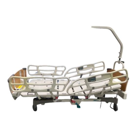
Introduction Chapter 1 1.9 BED ILLUSTRATION Your bed may have plastic siderails. Illustrated below is the FL17E equipped with steel siderails. SIDERAIL INNER CONTROL PANEL FOWLER SEAT SECTION KNEE GATCH PUSH PULL HANDLES FOOT SECTION FOOT BOARD CONTROL PANEL SIDERAIL OUTER... -
Page 12: Operation Guide
To disengage the wheel brakes, toggle the pedal to neutral position. 2.3 MOVING THE BED The FL17E is equipped with a 5th steer wheel (see page 11, "Bed Illustration") activated by two brake/steer pedals located on both sides of the bed. -
Page 13: Positioning Siderails
Operation Guide Chapter 2 2.4 POSITIONING SIDERAILS Keep siderails in the fully raised position and the sleep surface horizontal in its lowest position when the patient is unattended, unless its medical condition dictates otherwise. When raising the siderails, be sure that you hear the "click" that signals the locked condition. Pull firmly on the siderail to ensure it is locked into position.. -
Page 14: Siderail Function Guide
Operations Manual 2.6 SIDERAIL FUNCTION GUIDE OUTER CONTROL PANEL Right siderail Left siderail Figure 2.14A A: Push to raise Fowler C: Push to raise bed E: Push to raise Knee Gatch B: Push to lower Fowler D: Push to lower bed F: Push to lower Kne Gatch INNER CONTROL PANEL Right Siderail... -
Page 15: Foot Board Control Panel Guide
Operation Guide Chapter 2 2.7 FOOT BOARD CONTROL PANEL GUIDE SIDERAIL CONTROL SLEEP SURFACE POSITION SWITCHES LOCKOUT HEAD THIGH HI-LO SWITCHES TRENDELENBURG CONTOUR SWITCH AUTO CONTOUR PICTOGRAM (OPTIONAL) WHEN ON • Lockout Switches (A1 to A3) These three switches enable the selective lock out of the bed functions available to patient and nursing staff through the siderail control panels (inner and outer). - Page 16 Operations Manual • Hi-Lo Switches (D1 and D2) These two switches enable adjustment of the sleep surface height (Hi-Lo). D1: Push to raise the sleep surface. D2: Push to lower the sleep surface. • Trendelenburg Switch (E) This switch, when activated, enables both Trendelenburg positions through the Hi-Lo switches.
-
Page 17: Foley Bag Hooks
IV poles in conjunction with a Balkan frame. 2.11 PATIENT RESTRAINT STRAP LOCATIONS The FL17E is equipped with 12 separate locations for installing patient restraint straps. Ten of them are located on the mattress support edges directly across from each other whereas the remaining two are located on the top part of the head section, parallel to the head board (see page 11, "Bed Illustration"). -
Page 18: Cpr Emergency Release (Optional)
2.13 NIGHT LIGHT (OPTIONAL) The FL17E may be equipped with an optional photoelectric night light to illuminate the floor area around the bed. The night light turns on as the room lights dim. It is located on the left side of the frame at the foot end of the bed. -
Page 19: Accessories
Accessories Chapter 3 3. ACCESSORIES Listed below are all the accessories that may be attached to the FL17E as well as their maximum load capacity when applicable. • Ø1/2" removable anodized aluminum IV pole. Maximum load capacity: 11 lb (5 kg). -
Page 20: Appendix A: Fixing Board Permanently
Appendix A: Fixing Boards Permanently Appendix A: Fixing Board Permanently Figure A Tool necessary: 7/16" Wrench Procedure: One or both boards can be fixed permanently to the bed frame. Two 1/4" flat washers, two 1/4" spring washers and two 1/4-20 x 1 3/4" hexagon bolts are needed for the head board.
Need help?
Do you have a question about the FL17E and is the answer not in the manual?
Questions and answers