ST STM32L4 Manual
Simplifying microsoft azure connectivity with discovery kit iot node
Hide thumbs
Also See for STM32L4:
- User manual (110 pages) ,
- Programming manual (262 pages) ,
- Application note (58 pages)

Subscribe to Our Youtube Channel
Related Manuals for ST STM32L4


Summary of Contents for ST STM32L4
- Page 1 Simplifying Microsoft Azure Connectivity with the STM32L4 Discovery Kit IoT Node v1.5...
- Page 2 Agenda Presentation • Training Material Check/Installation Help • Overview of the STM32 Portfolio • Keil MDK-ARM Installation • Overview of the STM32L475 • Overview of the STM32L475 Discovery Kit IoT Node • STM32Cube Introduction • Keil MDK-ARM License Installation • Lab 1: Getting Started with STM32CubeMX - Blinking LED •...
- Page 3 Agenda Presentation • Lab 4: Monitor IoT Node Sensor Data sent to Azure Cloud • Lab 5: Manage IoT Node from the Azure Portal • Lab 6: Update IoT Node Firmware Over The Air (FOTA) • Bluetooth® Low Energy Overview •...
- Page 4 Training Material Check / Installation Help...
- Page 5 Seminar Day Check List • You would have received an email about a week ago with the Dropbox download link and instructions to install the necessary software. • Please use the printed checklist handed to you today to make sure that you have completed the necessary steps.
- Page 6 Training Material Installation • In case you have missed something, we have a few USB Flash drives with the Seminar Installer that we will pass around. This will install Tera Term, Device Explorer, NotePad++, and extract the seminar file to C:\STM32L4AzureSeminar •...
- Page 7 Training Material Installation (Cont’d) • If you see prompts such as the one below, please click “Install” to allow installing the ST-Link Device Drivers (there would be typically two such prompts).
- Page 8 Workshop Directory Content Documents Hands on Keil Software...
- Page 9 Keil MDK-ARM Tool Installation...
-
Page 10: Step 1. Keil Installation
Step 1. Keil Installation • C:\STM32L4AzureSeminar\Keil\ Browse to and Double-click on the file MDK524a.exe to begin the Keil toolchain installation. • Click through the default options and accept the ‘license agreement’ when prompted. • If you have an existing installation of Keil you should install in a new directory... - Page 11 Step 1. Keil Installation • Click on to begin the installation...
- Page 12 Step 1. Keil Installation • Click on Next...
- Page 13 Step 1. Keil Installation • Accept the license agreement and click on Next...
- Page 14 Step 1. Keil Installation • Please use the default directory path: C:\Keil_v5 and click on Next...
- Page 15 Step 1. Keil Installation • Enter your contact information and click on Next...
- Page 16 Step 1. Keil Installation • Installation begins…...
- Page 17 Step 1. Keil Installation • Before installing ULINK device drivers, Windows will block it and asks Don’t Install for confirmation. We will not use it so just click...
- Page 18 Step 1. Keil Installation • Setup complete…. Click Finish • We will manually install “Software Packs” a bit later If you get any errors for the “Pack Installer”, don’t worry. Just click OK, and we will get to that in a bit.
- Page 19 Overview of the STM32 Portfolio...
- Page 20 Today - STM32 Portfolio 10 product series / More than 40 product lines 2 010 CoreMark 400 MHz High-performance 856 DMIPS 398 CoreMark 608 CoreMark 1 082 CoreMark 120 MHz 180 MHz 216 MHz 150 DMIPS 225 DMIPS 462 DMIPS 245 CoreMark* 106 CoreMark Mainstream...
- Page 21 What is the MCU Ecosystem? All collaterals required to develop with an MCU Hardware Development Software Development Tools Tools Evaluation boards Configuration Tools Debug and Programming Probes Development & Debugging Tools Monitoring Tools Ecosystem Information and sharing Embedded Software Drivers Web site RTOS Product selectors...
- Page 22 Hardware Development Tools STM32 Discovery Evaluation parties Nucleo kits boards Flexible Prototyping, Typical Full feature prototyping, Creative From full evaluation use case Community demos evaluation to Extension open + + + possibilities hardware Arduino™ Connectivity ST Morpho...
- Page 23 STM32 Ecosystem SW Development Tools A complete flow, from configuration up to monitoring FREE IDE’s STM32CubeMX Partners IDEs STMStudio Configure & Generate Code Compile and Debug Monitor...
- Page 24 Development Software Architecture Mobile app prototyping & cloud prototyping Pre-integrated ST components and SW Sample applications Function Packs Sensors – motion, environment, light .. STM32Cube expansion SW High-value middleware Ultra-low power STM32Cube connectivity middleware STM32Cube Analog and mixed Expansion HAL...
- Page 25 STM32 Nucleo Development Boards A comprehensive range of affordable development boards for all STM32 microcontroller series, with unlimited unified expansion capability, and with integrated debugger/programmer Complete product range from ultra-low power to high-performance www.st.com/stm32nucleo...
- Page 26 STM32 Nucleo Expansion Boards http://www.st.com/x-nucleo 33 expansion boards covering all the key functions Power Move Sense Connect Translate Drive Actuate Motion & Power management Motor driver Audio environmental sensors Wi-Fi LED Boost Actuator Op-amp Proximity sensor Sub-GHz Microphone...
- Page 27 From Prototype to End Device Partnership with third parties - Form factor devices and customization Third Third Parties Parties Final Device Modular Blocks Form Factor Optimized Design Prototyping Field testing Volume Production Easy Porting of developed software to final Product HW/SW optimization and support for production...
- Page 28 Simple Vs Advanced Use Cases Expansion SW (X-Cube) Function Pack • • Prototype with a single expansion Create advanced use cases based board on multiple expansion boards Pre-integrated application example Sample applications Home Building Wearables applications automation Smart Things...
- Page 29 Overview of the STM32L475...
- Page 30 Overview of the STM32L475 Key features • Cortex M4 @ 80 MHz with DSP, FPU and ART • 1.71V – 3.6V supply 80 MHz Full functional • 1MB Flash dual bank / 128KB RAM • USB OTG FS –LPM Battery Charging Detection •...
- Page 31 Overview of the STM32L4 Discovery Kit IoT Node...
- Page 32 STM32L4 Discovery Kit IoT Node Get connected seamlessly! Smart Nodes Network Servers...
- Page 33 STM32L4 Discovery Kit IoT Node Open the door to remote services Direct connection to cloud servers Low-power long-range communication Smart Nodes Environmental awareness: humidity, pressure, temp Detection hub: motion, proximity, audio...
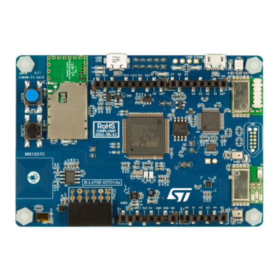
- Page 34 STM32L4 Discovery Kit IoT Node Multi-link communication, multiway sensing Arduino Connector USB-OTG User LEDs Wi-Fi Power ST-Link + VCP ST-Link Status LED User Button Sub GHz QSPI Flash Reset Button STM32L475VG MEMS Microphone NFC EEPROM ® Bluetooth Energy TOF Sensor...
- Page 35 Comprehensive Software Libraries Instant showcase SW Libraries for STM32L4 MCU & sensors Connectivity SW protocol stacks Cloud service connectors (AWS, Azure) Demo examples (X-CUBE-AWS, X-CUBE-AZURE, FP-CLD-AZURE1)
- Page 36 Wireless Connectivity – Wi-Fi • Inventek ISM43362 Wi-Fi Module • 802.11 b/g/n compliant Broadcom MAC/Baseband/Radio module • Fully contained TCP/IP stack to minimize host CPU requirements • FCC and CE certified • Secure Wi-Fi authentication supporting WEP-128, WPA-PSK (TKIP), WPA2-PSK...
- Page 37 ® Wireless Connectivity - Bluetooth • ® ST SPBTLE-RF Bluetooth Low Energy Module • Based on our ST BlueNRG-MS Wireless Network Processor • Bluetooth ® Low Energy 4.1 compliant • FCC and BQ certified module with integrated balun & antenna...
- Page 38 Wireless Connectivity - SubGHz • ST SPSGRF-915 Sub-GHz Module (915 MHz - US) • FCC and IC certified module with integrated balun & antenna • Supports 2-FSK, GFSK, MSK, GMSK, OOK and ASK modulation schemes • Long range (100s of meters) with an air data rate from 1 to 500 kbps...
- Page 39 Wireless Connectivity - NFC • ST M24SR64-Y Dynamic NFC/RFID Tag • ISO14443-A NFC Forum Type 4 RF interface • 106 Kbps Data Rate • I²C 1MHz interface • Up to 64kbit EEPROM memory • 128-bit password for data protection • 200 years data retention & 1Mcycles erase/write •...
- Page 40 USB OTG FS • Full Speed USB On-The-Go Communication Interface • PMOD • Peripheral Module Interface Supporting GSM, GPS, etc… • Arduino Connectors • Arduino Compatible Connectors to interface with additional ST X-NUCLEO or 3rd Party Expansion Board (eg: LoRa)
- Page 41 • LPS22HB Pressure Sensor • Integrated High Accuracy Proximity/Range Sensor • VL53L0X Time-of-Flight Range Sensor • Digital Microphones • MP34DT01 MEMS Digital Microphones • Voice & Audio Recognition Functions • Acoustic Beam Forming using the ST Open Software Acoustic Beam Forming Library...
- Page 42 Reset and User Buttons • Board Reset and Programmable Application Buttons • User LEDs • Programmable Application LEDs • QSPI Flash • 64Mbit for Data Storage and Program Execution • Selectable Power Supply • ST-Link, USB-OTG, Arduino or External Power...
- Page 43 Advantages of a Single Board • Easily Debug Hardware Issues. • Included Collateral is Tightly Coupled • BSP Included for all Board Components • Cloud Connectivity Reference Solutions Included • Cost Effective Development Solution (~$60) • No Need to Manage & Order Multiple Board SKUs.
- Page 44 Availability Mass Market SubGHz Regions with Part number Samples Availability frequency band authorized use B-L475E-IOT01A1 915 MHz B-L475E-IOT01A2 868 MHz Rest of the World...
- Page 45 STM32Cube Introduction...
- Page 46 STM32Cube Introduction • STM32Cube includes: • STM32CubeMX, a configuration tool for generating user driven initialization • Firmware collateral, delivered for every STM32 device series (i.e. STM32CubeF4) with: • An STM32 Abstraction Layer embedded software: STM32Cube HAL • A consistent set of Middleware: RTOS, USB, TCP/IP, Graphics, … STM32CubeMX STM32CubeL0 STM32CubeF4...
- Page 47 STM32CubeMX : Overview STM32CubeMX Peripherals & Middleware Wizard Pinout Wizard Power Consumption Clock Tree wizard Wizard...
- Page 48 STM32CubeMX : User Code Configuration Generates Initialization C Code based on user driven configuration!
- Page 49 STM32CubeMX : MCU Selector • Filter by: • Series • Line • Package • Peripherals...
- Page 50 STM32CubeMX : Pin-out Configuration • Pinout from: • Peripheral tree • Manually • Automatic signal remapping • Management of dependencies between peripherals...
- Page 51 STM32CubeMX : Clock Tree • Immediate display of all clock values • Management of all clock constraints • Highlight of errors...
- Page 52 STM32CubeMX : Peripheral Configuration • Global view of used peripherals and middleware • Highlight of configuration errors • Manage: • GPIO • Interrupts • DMA...
- Page 53 STM32CubeMX : Power Consumption Calculator • Power step definitions • Battery selection • Creation of consumption graph • Display of • Average consumption • Average DMIPS • Battery lifetime...
- Page 54 STM32Cube : Firmware Components Evaluation boards Discovery boards Nucleo boards Board Demonstrations Middleware level Applications Utilities Networking Graphics File system RTOS LwIP TCP/IP Host & Device STemWin FATFS FreeRTOS & Polar SSL Middleware HAL level Examples CMSIS Hardware Abstraction Layer API Board Support Packages Drivers STM32L431...
- Page 55 Keil License Installation...
- Page 56 Step 2. Keil License Installation • C:\STM32L4AzureSeminar\Keil\ Browse to and double-click on the file MDK-ARM_Pro_Eval_AddOn_2017-10.exe...
- Page 57 Step 2. Keil License Installation • Click on Next...
- Page 58 Step 2. Keil License Installation • Accept the license agreement and click on Next...
- Page 59 Step 2. Keil License Installation • Click on Next...
- Page 60 Step 2. Keil License Installation • Enter your contact information and click on Next...
- Page 61 Step 2. Keil License Installation • Click on Finish...
- Page 62 Keil Software Pack Installation...
- Page 63 Step 3. Keil Software Packs • Browse to your Desktop and double-click on Keil uVision5...
- Page 64 Step 3. Keil Software Packs • Keil will automatically prompt you to install the Device Family Packs. • Click on OK • doesn’t show up, click on Pack Installer icon If the Pack Installer...
- Page 65 Step 3. Keil Software Packs • We will manually import the STM32L4xx_DFP software pack… • In Pack Installer, Select File and then Import...
- Page 66 Step 3. Keil Software Packs C:\STM32L4AzureSeminar\Keil Browse to And then choose Keil.STM32L4xx_DFP.1.4.0.zip...
- Page 67 Step 3. Keil Software Packs After the STM32L4 Pack is installed, the Pack installer can be closed...
- Page 68 Board Distribution Participant Number (2 characters) Each board package will have a label with a unique number. During the lab sessions, this number will be referred to as your Participant Number.
- Page 69 ST-Link Driver Installation • Connect your PC to the USB ST-Link. • The board will be powered through the ST-Link connection. • ST-Link Status LED will be steady when ST-Link is recognized. USB ST-Link ST-Link Status LED...
- Page 70 Lab 1: Getting Started with STM32CubeMX – Blinking LED...
- Page 71 Launch STM32CubeMX • Open the STM32L4AzureSeminar folder on your Desktop. • Double click on the STM32CubeMX icon.
- Page 72 Create New STM32CubeMX Project • Click on New Project...
- Page 73 Select the Microcontroller • Expand Core...
- Page 74 Select the Microcontroller • Select ARM Cortex-M4...
- Page 75 Select the Microcontroller • Expand Series...
- Page 76 Select the Microcontroller • Select STM32L4...
- Page 77 Select the Microcontroller • Expand Line...
- Page 78 Select the Microcontroller • Select STM32L4x5...
- Page 79 Select the Microcontroller • Expand Package...
- Page 80 Select the Microcontroller Select LQFP100 Double-click on STM32L475VG...
-
Page 81: Gpio Selection
GPIO Selection • This example will use LED2 on the DK IoT board. PB14 Use the find toolbar and type PB14 Select PB14 and set it to GPIO_Output mode. Note: Board schematics can be found in the IoT board User Manual (UM2153) -
Page 82: Gpio Configuration
GPIO Configuration Select the Configuration Select GPIO under System. - Page 83 GPIO Configuration Select PB14. Set the User Label to LED2. Click OK...
-
Page 84: Project Settings
Project Settings Select Project -> Settings (Alt + P) - Page 85 Project Settings Set the project name to Lab1. Set the project location: C:\STM32L4AzureSeminar\Hands_On\ Set the IDE Toolchain to MDK-ARM Click OK.
- Page 86 Generate the Project • Click Generate Code (Ctrl + Shift + G)
-
Page 87: Open The Project
Open the Project • Click Open Project... - Page 88 Inside Keil MDK-ARM Project Window File Editor Window Build Output Window...
- Page 89 Edit main.c • Expand the file tree: 1. Expand Lab1 2. Expand Application/User 3. Double-click main.c...
- Page 90 Edit main.c Add the following code inside the while(1) loop (line 100): HAL_Delay(100); HAL_GPIO_TogglePin(LED2_GPIO_Port, LED2_Pin);...
- Page 91 Load and Run Click on the Build button or choose Project > Build Target Click the Start/Stop Debug Session button Click the Run button The board LED should now start blinking!
- Page 92 Microsoft Azure IoT Overview...
- Page 93 What is Microsoft Azure IoT? • Microsoft Azure Internet of Things (IoT) services enable secure, bidirectional communication between IoT devices and the cloud. Image Source: Microsoft...
- Page 94 What Is JSON • JSON (JavaScript Object Notation) is an open standard lightweight data-interchange format. As a text document, it is easy for users to read and write, and for machines to parse and generate. • JSON is completely language independent, but uses conventions that are familiar to C-family programmers including C, C++, C#, Java, JavaScript, Perl, Python and many others.
- Page 95 What is MQTT • MQTT stands for MQ Telemetry Transport. It is an extremely simple and lightweight messaging protocol, designed for constrained devices and low-bandwidth, high-latency or unreliable networks. • Designers use MQTT to minimize network bandwidth and device resource requirements, while ensuring reliability and some degree of delivery assurance.
- Page 96 How MQTT Works • MQTT uses a client/server model where every IoT device is a client and is connected to a server, called an MQTT broker (example: Azure IoT Hub). • The clients send messages to an address, called a topic. The MQTT broker will forward that message to all the clients subscribed to that topic.
- Page 97 Azure IoT Device Twin • A Device Twin is a JSON document that is used to store and retrieve current state information for a IoT node. • For each new device, the IoT Hub creates a Device Twin and uses it to maintain a persistent state of the device regardless of whether the device is connected to the Internet or not.
-
Page 98: Device Management
Device Management • IoT Hub enabled a set of Configuration device management patterns that can be adapted or extended to fit your needs • Reboot • Factory reset • Configuration • Firmware update • Report progress and status Image Source: Microsoft The pattern shown here is for Configuration: the back-end app uses the desired properties to configure software running on the device. - Page 99 Azure IoT Security • IoT Hub uses security tokens to authenticate devices and services • Devices and services use a shared access or symmetric key to sign and send security tokens to the IoT Hub to get access • IoT Hub also allows using X.509 certificates to authenticate a device...
- Page 100 Lab 2: Getting Started with Microsoft Azure IoT in 5 minutes!
- Page 101 Lab Overview • In this lab, we will: • Program the STM32L4 Discovery Kit IoT node with precompiled binaries • Input WiFi credentials through a terminal program • Establish connection to Azure IoT • View sensor data from your node on a web application...
- Page 102 Program your board • In Windows Explorer, navigate to the following folder: C:\STM32L4AzureSeminar\Hands_On\STM32 CubeFunctionPack_AZURE1_V3.1.0\Projects \Multi\Applications\Azure_Sns_DM\Binaries\B- L475E-IOT01\ • Open another Windows Explorer instance, and Click “Computer” and open the “DIS_L4IOT” drive; this could be assigned some drive letter such as D: or E: on your...
- Page 103 Program your board • We will use simple drag-and-drop programming that is enabled by the enhanced ST-LINK/V2-1 debugger built into the STM32L4 Discovery Kit • Drag and drop the “Azure_Sns_DM_BL_Web.bin” file to the Discovery kit “DIS_L4IOT” drive • Programming is complete when the LD6 LED stops flashing and the “DIS_L4IOT” drive disappears and reappears.
- Page 104 Open and Configure Serial Terminal • Open the STM32L4AzureSeminar folder on your Desktop. Double-click on the TeraTerm shortcut...
- Page 105 Open and Configure Serial Terminal (Cont’d) Select the STMicroelectronics STLink Virtual COM Port Click...
- Page 106 Open and Configure Serial Terminal • Set baud rate speed in serial terminal to 115200 (Setup Serial port) Note: If you see any Japanese characters, go to Setup > General and change language to “UTF-8”...
-
Page 107: Reset The Board
Reset the Board • Press the black Reset button • Then, within 3 seconds, press the blue User button User Button Reset Button... - Page 108 Change the default WiFi Credentials • Type your responses questions as follows: • Press Enter after each response Do you want to change them?(y/n)? Do you want to read them from NFC?(y/n) Enter the SSID: stm32iot Enter the PassWd: stm32iot Enter the encryption mode (0:open, 1:WEP, 2:WPA/WPA2-Personal): Note: You cannot use backspace or delete if you make a typo;...
- Page 109 The WiFi credentials are stored in MCU Flash memory for future • Board is automatically registered to ST’s demonstration Azure IoT Hub • The WiFi module’s MAC address is used as the unique identifier • The unique URL displayed also uses...
- Page 110 Open the Web Application • Multiple ways to open the web app: • Double click on the URL in the TeraTerm terminal window to lauch your browser • Use your Android phone to touch the NFC on the board to launch the URL in your browser...
- Page 111 STM32ODE IoT Web Dashboard • The STM32ODE Web Dashboard is a web application hosted on Azure cloud • Connects to IoT hub and retrieves sensor data sent from device to cloud • Plots data on easy to view graphs • Separate tabs for each sensor •...
- Page 112 Visualize Sensor Data Connected: Device is connected to IoT Hub Disconnected: Device is not connected to IoT Hub now Switch to device management view Enabled: Device can send data if connected Select dataset to be visualized Warning: Device close to reaching maximum allowed messages per day Set alert threshold and view alerts in graph Disabled:...
- Page 113 Explore Device Management Features...
- Page 114 FP-CLD-AZURE1 Function Pack Overview...
- Page 115 Include middleware and drivers for Wi-Fi connectivity, NFC, inertial and environmental sensors • Provide software interface to access temperature and humidity sensor (HTS221), pressure sensor (LPS22HB), inertial sensors (LIS3MDL, LSM6DSL), ToF and gesture detection (VL53L0X) and to write and read the M24SR64-Y RFID/NFC tag Latest info available at www.st.com FP-CLD-AZURE1...
- Page 116 FP-CLD-AZURE1: Folders Structure Drivers and BSP for Discovery Kit IoT node WiFi and NFC middleware Azure IoT SDK and mbedTLS Bootloader to handle FW update...
- Page 117 FP-CLD-AZURE1: Folders Structure (Cont’d) Sample application based on Azure IoT SDK for data telemetry and Device Management Solution files for 3 IDE: • IAR (EWARM) • System Workbench (SW4STM32) • ARM Keil (MDK-ARM) C:\STM32L4AzureSeminar\Hands- on\STM32CubeFunctionPack_AZURE1_V3.1.0\Projects\Multi\Applications\Azure_Sns_DM\MDK-ARM\B- L475E-IOT01\...
- Page 118 Hardware Abstraction Layer API Boards Support Packages Drivers STM32 SPWF01SA LPS25HB LSM6DS0 LIS3MDL M24SR64 HTS221 LPS22HB LSM6DSL LSM303AGR HW Components X-NUCLEO-IKS01A1 STM32 Nucleo Board Expansion Board X-NUCLEO-IDW01M1 X-NUCLEO-NFC01A1 Expansion Board Expansion Board X-NUCLEO-IKS01A2 STM32L4 IoT Discovery Expansion Board Development boards...
- Page 119 Lab 3: Connect your STM32 IoT Node to Azure IoT Hub...
- Page 120 Introduction • In this lab, we will: • Create and login to a Free Azure account • Create an IoT Hub • Create a new Device node and retrieve it’s Connection String • Setup your IoT node using the sample application provided with the Function Pack...
- Page 121 • For this seminar, we will use Azure login credentials and IoT Hub already created for this workshop by ST • For this workshop session, you should skip the steps to create a new Azure account and to create the new IoT Hub •...
- Page 122 Step 1: Create a Free Azure account • https://azure.microsoft.com/en-us/free/ • Need to create a Microsoft account if you don’t already have one • Need mobile phone and credit card for identity verification • Free $200 credit; will not charge credit card; will not automatically renew at the end of trial period.
- Page 123 Step 2: Log into your Azure account • Make sure your laptop is connected to the internet • Go to https://portal.azure.com and sign in with the credentials below: • login: SeminarParticipant@iotcloudservicesst.onmicrosoft.com • password: STM32iot...
- Page 124 Step 3: Create an IoT Hub • Internet of Things IoT Hub In the left jump-bar, click on We did these steps for you...
- Page 125 Step 3: Create an IoT Hub (Cont’d) Insert a unique id for your IoTHub Sample application doesn’t require a specific tier; the free tier can be used. We did these steps for you The Subscription would be “Free Trial” You can create a container folder for your Azure services Geographical region where the IoT Hub will be hosted Create the IoT Hub...
- Page 126 IoT Hub Created • The IoTHub is now included in the list of resources and resource groups...
- Page 127 Step 4: IoT Hub Overview Select IoT Hub • Click on the All resources icon to view all you resources • Click on the IoT Hub just created from the list of resources in the left jump bar...
- Page 128 Step 4: IoT Hub Overview wait for “Active” status (Cont’d) • If you see the status of your newly created IoT Hub as “Activating”, you may need to wait for a few minutes for activation. Note: You may also have to log out and log back in for status to change from “Activating”...
- Page 129 Step 4: IoT Hub Overview • The overview page will be opened. It shows the essential data of your IoT Hub and the current usage in terms of registered devices and messages received.
-
Page 130: Step 5: Create A New Device
Step 5: Create a new device in the IoT Hub registry • Click Device Explorer... - Page 131 Step 5: Create a new device in the IoT Hub registry (Cont’d) • Click Add...
- Page 132 Step 5: Create a new device in the IoT Hub registry • “Thing_XX”: “XX” is your Insert your Device ID participant number (2 characters) printed on the box • Check Auto Generate Keys • Enable Connect device to IoT Hub •...
- Page 133 Step 6: Retrieve Connection string • After the device is created, open the device in the Device Explorer pane.
- Page 134 Step 6: Retrieve Connection string (Cont’d) • Copy the Device Connection string into Notepad.
- Page 135 Step 7: Open Keil Project • Browse to the project location: C:\STM32L4AzureSeminar\Hands-on\STM32CubeFunctionPack_AZURE1_V3.1.0\Projects\Multi\Applications\Azure_Sns_DM\MDK- ARM\B-L475E-IOT01\ • Double click on Project.uvprojx project file to bring up Keil...
- Page 136 Step 7: Open Keil Project (Cont’d) • Expand Application/User Group in Project Explorer window Azure sample application Platform dependent functions...
- Page 137 Step 8: Disable Registration and set Connection String • Project Window double- click on console.c • Right-click on line 46 • Click Open document “azure1_config.h”...
- Page 138 Step 8: Disable Registration and set Connection String (Cont’d) • In file azure1_config.h • Comment Line 61 • Uncomment line 74 and paste the Connection String retrieved in previous step (slide 134) replacing "HostName=<host_name>;DeviceId=<device..." Make sure to have the Connection String in between double-quotes aka “….”...
- Page 139 Step 9: Rebuild the Project • Click on Project menu • Click on Rebuild all target files In the Build Output window, it should report ‘ 0 Errors(s), 0 ’ Warnings You are now ready to Program your STM32...
- Page 140 Step 10: Program IoT node • Click on Flash menu • Click on Download Progress can be monitored in the bottom left status bar. Your IoT node should now be programmed...
-
Page 141: Step 11: Check Connection
Step 11: Check Connection • Restart the application by pressing the Reset Button on Nucleo Development Board (Black button). Wait until the board is connected to Wi-Fi access point and to the IoT Hub • Each 2 seconds, a message is created and transmitted to the IoTHub using MQTT protocol. For each message transmitted, a confirmation acknowledge is received back by the device... - Page 142 Flash the IoT node Using Installed Script (Cont’d) The STM32 flash memory is divided in different regions: The first region contains a custom boot loader (required for firmware update) The second region contains the application firmware The third region is used in a firmware update procedure to store the new downloaded firmware before updating it, and to save the Wi-Fi credentials inside the Meta Data Manager.
- Page 143 Flash the IoT node Using Installed Script • Once built the project, it is necessary to launch the “.bat” script located in folder C:\STM32L4AzureSeminar\Hands- on\STM32CubeFunctionPack_AZURE1_V3.1.0\Projects\Multi\Applications\Azure_Sns_DM\MDK-ARM\B- L475E-IOT01 In order to flash the MCU, the usage of the script is required to install in the MCU a bootloader together with the project binary.
- Page 144 C:\Program Files (x86)\STMicroelectronicsTraining\ST-LINK\ which is the one used by default in the script • You can verify that the path in the script correspond to your installation path for ST-Link utility Note: If you see an error “The system cannot find the path specified”, please run...
- Page 145 Flash the IoT node Using Installed Script (Cont’d) • Double click on CleanAzure_Sns_DM.bat to launch the script • Once done, the console should show that the board was programmed successfully • Press any key to close the console...
- Page 146 Lab 4: Monitor IoT Node Sensor Data sent to Azure Cloud...
- Page 147 Introduction • The sample application reads raw data from sensors board, compose a message and through Azure IoT SDK iteratively transmits messages to your IoT Hub • In this lab you will learn how to visualize the log of messages received by your IoT Hub using a Web App •...
- Page 148 Introduction MQTT device-to-cloud messages "deviceId":"c47f51037c8e", "messageId":3123, HTTP & WebSocket "Temperature":30.719666, "Humidity":30.874012, "ts":"2017-10-10T22:03:14Z"...
- Page 149 Step 1: Open Web App • Open • http://stm32iotapp.azurewebsites.net • Select Device ID...
- Page 150 Step 2: Visualize real-time sensor data • Optionally, check data by blowing onto the temperature sensor • Monitor the spike in the real-time visualization...
- Page 151 Create your own IoT Web App • To learn how to create your own “Web App”, go to: https://docs.microsoft.com/en-us/azure/iot-hub/iot-hub-live-data- visualization-in-web-apps • You will learn to • Create a web app in the Azure portal. • Get your IoT hub ready for data access by adding a consumer group. •...
- Page 152 Customize Usage of the Sensor Board • The message transmitted to your IoT Hub is composed inside function SendSNSData() in file AzureClient_mqtt_DM_TM.c (Azure_Sns_DM/User) Read raw data from sensors to Azure1 data structure, using driver APIs (BSP_TEMPERATURE_Get_Temp, BSP_TEMPERATURE_Get_Hum, etc.) Convert sensors data structure into a JSON string Create message handler Send the message...
- Page 153 Customize Usage of the Sensor Board (Cont’d) • Function SendSNSData() is called by a timer interrupt every two seconds. Transmission rate for messages can be changed using Desired Properties or directly in the code in AzureClient_mqtt_DM_TM.c by using ChangeTelemetryInterval API •...
- Page 154 Lab 5: Manage IoT Node from Azure portal...
- Page 155 Introduction • IoT Hub provides three options for device apps to expose functionality to a back-end app: • Direct methods for communications that require immediate confirmation of the result. Direct methods are often used for interactive control of devices such as turning on a fan. •...
- Page 156 Step 1: Send cloud-to-device message • In the Azure portal, go to your IoT Hub Device Explorer • Select you Device • Click on Message to Device...
- Page 157 Step 1: Send cloud-to-device message Turn LED On • Copy-paste the message below to the Message Body field to turn the green LED on: • {"Name":"LedOn", "Parameters":{}} • Click on Send...
- Page 158 Step 2: Visualize and Interpret Message received by device • Each message received by the device from IoT Hub is printed over serial terminal • Microsoft Azure IoT SDK provides means to define user specific callbacks (actions) associated to certain commands •...
- Page 159 Step 3: Send cloud-to-device message Turn LED Off • Copy-paste the message below to the Message Body field to turn the green LED off: • {"Name":"LedOff", "Parameters":{}} • Click on Send...
- Page 160 Step 4: Send cloud-to-device message Blink LED • Copy-paste the message below to the Message Body field to blink the green LED: • {"Name":"LedBlink", "Parameters":{}} • Click on Send...
- Page 161 Customize Code to Execute Commands • You can define a new action associated to a message, see example in AzureClient_mqtt_DM_TM.c Pause is the message and the name of the callback (action) that will be executed • Define user specific implementation for the message. See example for Pause in AzureClient_mqtt_DM_TM.c •...
- Page 162 Lab 6: Firmware-over-the-air (FOTA) Update...
- Page 163 Introduction • In this lab, we will: • Trigger a Firmware-Over-The-Air (FOTA) Update using a simple binary stored on the cloud.
- Page 164 Over-The-Air Firmware Update Image Source: Microsoft...
- Page 165 Step 2: Initiate Firmware Update method • Close the Message to Device window...
- Page 166 Step 2: Initiate Firmware Update method • Click on Direct Method...
- Page 167 Step 2: Initiate Firmware Update method • Copy-paste the message below to Method name FirmwareUpdate • Copy-paste the message below to Method payload {"FwPackageUri": "https://stm32iot.blob.core.windows.net/ FirmwareUpdate firmware/blinky.bin"} {"FwPackageUri": "https://stm32iot.blob.core.windows.net/firmware/blinky.bin"} • Click on Invoke Method...
- Page 168 Step 2: Monitor Firmware Update Execution on Device Via Serial Terminal Erase FLASH memory and download new firmware When download is finished, the board will restart and load the new firmware...
- Page 169 Step 2: Monitor Firmware Update Execution on Device Via Serial Terminal (Cont’d) When the download is completed, the board is reset and the new firmware is installed. Download is finished The board restarts and loads the new firmware...
- Page 170 STM32 boot sequence after a Firmware Update...
- Page 171 ® Bluetooth Low Energy Overview...
-
Page 172: What Is Bluetooth
® What is Bluetooth Low Energy? • ® Bluetooth Low Energy technology • Short range wireless ISM 2.4 GHz • Optimized for ultra low power • <15 mA peak current • <50 uA average current • Fast connection procedure • Client server architecture •... - Page 173 ® Bluetooth Low Energy Branding 2011 2017 Two flavors Back to one flavor • ® An implementation of the Bluetooth core system has only • Ultra low power consumption being a pure low energy one Primary Controller which may be one of the following implementation configurations: •...
- Page 174 ® Bluetooth Low Energy Stack Partitioning • The application collects & computes Application & the data to be transmitted over ® Bluetooth Low Energy Profiles Bluetooth® Low Energy. ® BLUETOOTH LOW ENERGY STACK • Data transmission and reception ® uses the Bluetooth Low Energy GATT stack services and characteristics...
- Page 175 ST BlueNRG-MS Solution Integration • ® Single mode Bluetooth Low Energy wireless network processor • 2.4GHz RF transceiver Customer Code ® Bluetooth • Cortex-M0 microcontroller (running the BT MS stack) Library Energy Profiles Flexibility • AES 128-bit co-processor Source Code •...
- Page 176 ® Demo: Bluetooth Low Energy Pairing...
- Page 177 Lab Goal • This lab will ensure that your BlueNRG device has a unique name and MAC address. • This lab will demonstrate how to configure a BlueNRG device, communicate with a smartphone and display heart rate data.
- Page 178 Lab Goal • The DK IoT Node will be used as server while the applet is a client. • You will need to download the STM32 BLE Profiles application available on the Apple App store or the Android Google Play store.
- Page 179 • One of the packages installed on your PC is the STM32CubeL4 • This package includes several applications made for the STM32L4 DK IoT node board • The zip file is extracted within your STM32Cube repository folder • The zip file is installed by the Seminar Installer...
- Page 180 We are going to configure the program to give each BlueNRG module a unique MAC address and Unique device name. The device name will be used later to identify your board within the ST BLE Profiles app. Close the previous Keil MDK-ARM project. Project.uvprojx...
- Page 181 BlueNRG Module configuration (1/4) Expand the file tree: 1. Expand Application/Common/ble_services 2. Double-click hrs.c 3. Right-click config.h on line 48 Open document “config.h” 4. Select...
- Page 182 BlueNRG Module configuration (2/4) • ‘ab’ CFG_ADV_BD_ADDRESS Replace the in the (line 171) with your participant number found on your box (2 characters).
- Page 183 BlueNRG Module configuration (3/4) 1. Expand Application/HR_Example 2. Double-click hr.c...
- Page 184 BlueNRG Module configuration (4/4) • ’X’,’X’ Add your participant number within single quotes in place of the local_name (line 242) table as shown above.
- Page 185 Load and Run Click on the Build button or choose Project > Build Target Click the Start/Stop Debug Session button Click the Run button...
- Page 186 Pair with STM32 BLE Profiles App Android • ® Make sure Bluetooth is active on your phone • Using your phone, open the STM32 BLE Profiles app. • For iOS users click on Scan.
- Page 187 Pair with STM32 BLE Profiles App Android • Identify your device with device name HR_L475_IoT_XX, is the number you entered during the board configuration. Click on your device name.
-
Page 188: Connect To Your Device
Connect to your Device • iOS users, please click Connect on the next screen (iOS) - Page 189 Select the Heart Rate Profile Android • Click on Heart Rate under Services (iOS) or Profiles (Android)
- Page 190 Select the Heart Rate Profile • iOS users, please click on Heart Rate Measurement...
- Page 191 Display HR Data Android • You should see the simulated heart rate.
- Page 192 • Make your own custom web application by following the Azure guide linked earlier • Use the rich set of sensors on the board to get creative! • Post your projects or ideas on the ST Community website to gather feedback and get support:...
- Page 193 Releasing Your Creativity /STM32 @ST_World st.com/e2e www.st.com/stm32...
- Page 194 Appendix 1: Upload firmware to Azure storage...
- Page 195 Step 1: Prepare Firmware binary for Upload to Azure Cloud Storage directory, rename your Azure_Sns_DM.bin to Thing_XX.bin where In your project is your participant number...
- Page 196 Step 2: Upload firmware to Azure storage • Open the stm32iot Storage account from the Azure Portal Dashboard...
- Page 197 Step 2: Upload firmware to Azure storage • Click on the firmware container...
- Page 198 Step 2: Upload firmware to Azure storage • Click on Upload...
- Page 199 Step 2: Upload firmware to Azure storage • Browse to the location of your binary (located in your project folder) • Click on Upload...
- Page 200 Step 3: Retrieve firmware URL Once the binary has been uploaded: • Double-click on your Thing_XX.bin blob • Click to copy the blob...
- Page 201 Appendix 2: Using Device Explorer tool to manage devices connecting to your IoT hub...
- Page 202 Step 1: Visualize IoT Hub Credentials and Retrieve Connection String • Within settings pane for Hub, click on Shared access policies pane • Click on iothubowner the left side bar • Copy the Connection string Notepad++...
- Page 203 Step 2: Launch Device Explorer Desktop Application Open STM32L4AzureSeminar folder in your Desktop Double-click on the Device Explorer shortcut...
- Page 204 Step 3: Update IoT Hub Connection String in Device Explorer • Paste the IoT Hub connection string (from Page 64) in the IoT Hub Connection String • Click on Update...
- Page 205 Step 3: Update IoT Hub Connection String in Device Explorer (Cont’d) • On successful update the section Shared Access Signature populated with the three components of the IoT Hub Connection String: • Key Name • Key Value • Target...
- Page 206 Step 4: Create a New Device in Device Explorer • You are now ready to create your IoT device in the IoT Hub: • Go to tab Management • Click on Create • Create Device window will appear Primary and Secondary showing keys which are automatically generated...
- Page 207 Step 4: Create a New Device in Device Explorer (Cont’d) • For this tutorial we rely on device authentication with keys. However, also device identification with X509 certificated is supported by NucleoL4 • “Thing_XX”: “XX” is your Insert your device ID participant number (2 characters) printed on the •...
- Page 208 Step 4: Create a New Device in Device Explorer (Cont’d) • An entry for your device has been created and listed in Management tab of your device explorer. This entry contains the connection string be stored in the device to authorize access to your IoT Hub...
- Page 209 Step 5: Retrieve Connection string for added device • “Thing_XX”: Select your device ID “XX” is your participant number (2 characters) printed on the box • Use the mouse right click for context menu then select Copy connection string for selected device •...
- Page 210 Step 6: Visualize Messages in Device Explorer • Select Data • Device ID, Select your device “Thing_XX”: “XX” is your participant number (2 characters) • Click on Monitor to start visualizing the log of messages received by IoTHub...
- Page 211 Step 7: Send Message to Device with Device Explorer: Turn LED On • Select Message To Device • Device ID, Select your device “Thing_XX”: “XX” is your participant number (2 characters) • Copy-paste the message below to the Message field to turn the green LED on: •...
- Page 212 Step 8: Call FW-update Method on Device with Device Explorer • Select Call Method on Device • Select your device “Thing_XX”: “XX” is your participant number (2 characters) FirmwareUpdate • Copy-paste the message below to {"FwPackageUri": "https://stm32iot.blob.core.windows.net/firmware/blinky.bin"} Method name FirmwareUpdate Copy-paste the message below to Method payload {"FwPackageUri":...
- Page 213 Releasing Your Creativity /STM32 @ST_World st.com/e2e www.st.com/stm32...
Need help?
Do you have a question about the STM32L4 and is the answer not in the manual?
Questions and answers