ST STM32F0 Series Application Note
Getting started with touch sensing control on stm32 microcontrollers
Hide thumbs
Also See for STM32F0 Series:
- Programming manual (91 pages) ,
- Application note (29 pages) ,
- Application note (56 pages)
Table of Contents
Advertisement
AN5105
Application note
Getting started with touch sensing control on STM32 microcontrollers
Introduction
This document helps customers to quickly locate information regarding touch sensing on STM32 microcontrollers.
It is applicable to STM32F0, STM32F3, STM32L0, STM32L1 and STM32L4 Series products. It lists all the existing application
notes and user manuals covering touch sensing. It indicates where the key aspects of touch sensing are documented.
It also explains how to build touch sensing applications on STM32L0538-DISCO and STM32F072B-DISCO discovery boards
using the STM32CubeMx graphical interface.
AN5105 - Rev 1 - September 2018
www.st.com
For further information contact your local STMicroelectronics sales office.
Advertisement
Table of Contents

Subscribe to Our Youtube Channel
Related Manuals for ST STM32F0 Series


Summary of Contents for ST STM32F0 Series
- Page 1 It indicates where the key aspects of touch sensing are documented. It also explains how to build touch sensing applications on STM32L0538-DISCO and STM32F072B-DISCO discovery boards using the STM32CubeMx graphical interface. AN5105 - Rev 1 - September 2018 www.st.com For further information contact your local STMicroelectronics sales office.
-
Page 2: General Information
AN5105 General information General information ® This document applies to Arm -based devices. Note: Arm is a registered trademark of Arm Limited (or its subsidiaries) in the US and/or elsewhere. AN5105 - Rev 1 page 2/52... -
Page 3: Terminology And Principle
AN5105 Terminology and principle Terminology and principle Terminology The touch sensing most relevant acronyms are described below: • Acquisition mode – CT: Charge-Transfer acquisition principle. This mode is used on STM32 microcontrollers. • Touch sensing STM32 peripheral – TSC: touch sensing controller peripheral –... -
Page 4: Table 1. Change Transfer Principle Documentation
Sampling capacitor selection guide for MCU based AN4310 Charge transfert acquisition principle overview touch sensing applications Guidelines for designing touch sensing applications AN4312 Capacitive sensing technology in ST with surface sensors AN4316 Tuning a STMTouch-based application Charge transfer periode tuning STM32L4 On Line Training... -
Page 5: Document Reference
AN5105 Document reference Document reference Figure 2. Main documentation tree shows the main documentation tree related to TSC and TSL. Figure 2. Main documentation tree Application Note overview (AN5105) Getting Started STM32 On-line Tuning with TSL Training (AN4316) (UM1913) Sampling Sensors Conducted Noise Capacitor... -
Page 6: Stm32L4 Touch Sensing Controller Online Presentation
STM32L4 touch sensing controller online presentation STM32L4 touch sensing controller online presentation An online training is available under our website www.st.com. Insert the STM32L4 Online Training” string in the "Search" fuction and press enter. To find it use the function "Search" and insert the strings “STM32L4 Online Training”. -
Page 7: Main Characteristics
AN5105 Main characteristics Main characteristics Description The following Figure 5. TSC characteristics shows all touch sensing controller (TSC) characteristics and their correlation. The TSC main characteristics are described in the following pages. Figure 5. TSC characteristics Signal Charge Noise Sensitivity Sensor threshold transfer... -
Page 8: Table 3. Signal Threshold Usage Documentation
AN5105 Signal threshold Figure 6. STMStudio outputs • On software side: – Relevant information are located in tsl_conf.h and tscl_user.c files. – Threshold (xx_TH) can be adjust in tsl_conf_tsc.h file.: See below an example: #define TSLPRM_TKEY_DETECT_IN_TH (64) #define TSLPRM_TKEY_DETECT_OUT_TH (60) #define TSLPRM_TKEY_CALIB_TH (56) #define TSLPRM_LINROT_DETECT_IN_TH (50) #define TSLPRM_LINROT_DETECT_OUT_TH (40) -
Page 9: Charge Transfer
AN5105 Charge transfer Table 3. Signal threshold usage documentation Title Chapters Developing applications on STM32Cube with UM1913 Debug with STMStudio STMTouch® touch sensing library Monitoring STMTouch driver variables using STMStudio Tuning of the Thresholds AN4316 Tuning a STMTouch-based application Touchkeys thersholds Linear and Rotary touch sensors thresholds Charge transfer The acquisition is based on the measurement of the sensor channel capacitance. -
Page 10: Sensitivity
AN5105 Sensitivity Sensitivity Sensitivity is a key point in touch sensing applications. The sensitivity can be improved by: • Reduce air gap • Reduce panel thickness • Choose dielectric with higher ε • GND plane must not too close from shield and sensors •... -
Page 11: Sensor
AN5105 Sensors Sensors • It is recommended to use the same shape for all electrodes. • The touchkeys can be customized by the drawing on the panel. TSL compensates capacitance differences. • Acquisition time and processing parameters can be optimized when electrodes have similar capacitance. Sensor size example Figure 8. -
Page 12: Linear Or Slider
AN5105 Sensors 5.5.2 Linear or slider A linear is a set of contiguous capacitive electrodes. Figure 9. Interlaced linear touch sensor with 3 channels / 4 electrodes (half-ended electrodes design) shows a slider used on a discovery board. Figure 9. Interlaced linear touch sensor with 3 channels / 4 electrodes (half-ended electrodes design) Up to 60 mm Full band width 3.6 mm... -
Page 13: Rotary Or Wheel
AN5105 Sensors 5.5.3 Rotary or wheel A rotary is a set of contiguous capacitive electrodes. Figure 10. Interlaced patterned rotary sensor with 3 channels / 3 electrodes Full band width 2.0 - 4.0 mm Tooth pitch 2.0 - 4.0 mm 0.2 - 0.3 mm 2 mm LEGEND:... -
Page 14: Active Shield Or Driven Shield
AN5105 Sensors 5.5.4 Active shield or driven shield Active shield or driven shield. (this name is used in some application notes) drives the shield plane with the same signal as the electrode. There are several advantages using Active Shield instead of a grounded shield: •... -
Page 15: Layout And Pcb
AN5105 Layout and PCB Layout and PCB Rules to follow to improve TSC systems 5.6.1 Led rules Figure 12. Led layout example Figure 13. Example of cases where a LED bypass capacitor is required Table 11. Led rules documentation gives a list of documents containing information about led rules. Table 11. -
Page 16: Electrode Not Located On Pcb
AN5105 Layout and PCB 5.6.2 Electrode not located on PCB It is possible but it is not recommended, because when the electrode it isn't located on PCB, the sensitivity decreases and additional extra parasitic capacitances are added. Figure 14. Electrode not located on PCB example Spring Spacer (cylinder Flex PCB... -
Page 17: Ground, Shield And Sensors
AN5105 Layout and PCB 5.6.3 Ground, shield and sensors Table 13 gives a list of documents containing information about the layout . Table 13. Layout documentation Title Chapters • PCB and Layout Guidelines for designing touch sensing applications AN4312 • Ground considerations with surface sensors •... -
Page 18: Figure 17. Track Routing
AN5105 Layout and PCB Figure 17. Track routing Figure 18. Track routing recommendation At least 2 mm (4 - 5 mm is recommended) At least Ground plane or twice the ground track Any application track track width (LED, power, Com.) As thin as At least twice the panel thickness... -
Page 19: Figure 19. Shield
AN5105 Layout and PCB Figure 19. Shield Top layer Bottom layer Ground plane Track width (W) ~ 0.21 3 x W 3-4 mm Active shield Sense plate AN5105 - Rev 1 page 19/52... -
Page 20: Faq
AN5105 Layout and PCB 5.6.4 System keys points: • Direct connection between earth and board ground is required to avoid conducted noise issues. • Conductive painting on the front panel must be avoid. • Robust mechanical assembly is required. Layout keys points: •... -
Page 21: Noise
AN5105 Noise Noise Noise is a key point for touch sensing applications. Noise can come from Power supply. 5.7.1 Power supply Main rules to follow: • Place Buzzer and LED before LDO. • Place LDO close to MCU. Figure 20. Typical power supply schematic LEDs Touch sensing... -
Page 22: Noise Immunity
AN5105 Noise 5.7.3 Noise immunity Noise filtering can be done on hardware and software (TSL) sides. Table 16. Noise immunity documentation gives a list of documents containing information about the noise immunity. Table 16. Noise immunity documentation Title Chapters Developing applications on STM32Cube with UM1913 Noise filters STMTouch®... -
Page 23: Tuning
AN5105 Tuning Tuning For tuning purpose dedicated application note are available. Sensors Table 18. Sensors documentation gives a list of documents containing information about the sensor. Table 18. Sensors documentation Title Chapters Guidelines for designing touch sensing applications AN4312 All chapters with surface sensors Table 19. -
Page 24: Getting Started Tsc With Stm32Cubemx
AN5105 Getting started TSC with STM32CubeMX Uses cases How to set-up an TSC application based on TSL is esplained in the following two examples. These examples describe the way to set-up TLS on STM32F072B-DISCO and STM32L0538-DISCO discovery boards. This description can be used as example to set-up others TSC series such us L4, F3, L0, L1 and L4. An STM32CubeMX new feature is available from version 4.24.0. -
Page 25: Discovery Board: Stm32F072B-Disco
The STM32F072 Discovery kit helps the user to discover the STM32F072, which has the full set of features available in the STM32F0 Series, and to develop his applications easily. It includes everything required for beginners and experienced users to get started quickly. - Page 26 AN5105 Discovery board: STM32F072B-DISCO Figure 23. STM32F072B-DISCO board schematics AN5105 - Rev 1 page 26/52...
-
Page 27: Tsc Group And Sensor Activation
AN5105 Discovery board: STM32F072B-DISCO 7.2.2 STM32F072B-DISCO TSC group and sensor activation To activate the TSC group, sampling capacitors and sensor channels follows the below steps: • activate TSC according schematics information. • desactivate unrelevant peripheral like USB, SPI, NCF(L0), EPaper(L0), MFX(L0) SWD peripheral must be set according to Figure 24 Figure 24. -
Page 28: Stm32F072B-Disco Clock Tree
AN5105 Discovery board: STM32F072B-DISCO Figure 26 shows the results obtained. Figure 26. STM32F072B-DISCO pinout overview 7.2.3 STM32F072B-DISCO clock tree It uses the default clock tree setting. Figure 27. STM32F072B-DISCO clock configuration AN5105 - Rev 1 page 28/52... -
Page 29: Stm32F072B-Disco Touchsensing Library
AN5105 Discovery board: STM32F072B-DISCO 7.2.4 STM32F072B-DISCO touchsensing library To activate the TLS usage, switch on TOUCHSENSING box configuration. Figure 28. TOUCHSENSING box configuration Select three channels Linear slider and assign dedicated Gx_IOy (see previous chapter or schematics for details). • For training purpose, we can used three channels Linear slider as three keys sensors. -
Page 30: Figure 30. Stm32F072B-Disco Sensor Selection Step2
AN5105 Discovery board: STM32F072B-DISCO Figure 30. STM32F072B-DISCO sensor selection step2 Figure 31. STM32F072B-DISCO sensor selection step3 AN5105 - Rev 1 page 30/52... -
Page 31: Figure 32. Stm32F072B-Disco Sensor Selection Step4
AN5105 Discovery board: STM32F072B-DISCO Figure 32. STM32F072B-DISCO sensor selection step4 Figure 33. STM32F072B-DISCO sensor selection step5 AN5105 - Rev 1 page 31/52... -
Page 32: Stm32F072B-Disco Software Project Generation
AN5105 Discovery board: STM32F072B-DISCO 7.2.5 STM32F072B-DISCO software project generation Now, it is possible to generate the complete software project based on TSC HAL and TSL. Figure 34 Figure 37 show all these steps. Figure 34. STM32F072B-DISCO software generation step1 Figure 35. STM32F072B-DISCO software generation step2 AN5105 - Rev 1 page 32/52... -
Page 33: Figure 36. Stm32F072B-Disco Software Generation Step3
AN5105 Discovery board: STM32F072B-DISCO Figure 36. STM32F072B-DISCO software generation step3 Figure 37. STM32F072B-DISCO IDE workspace AN5105 - Rev 1 page 33/52... -
Page 34: Software Basic Algorythm
HAL_GPIO_WritePin(LD4_GPIO_Port, LD4_Pin, GPIO_PIN_RESET); HAL_GPIO_WritePin(LD6_GPIO_Port, LD6_Pin, GPIO_PIN_RESET); else //if(MyLinRots[0].p_Data->StateId == TSL_STATEID_RELEASE) HAL_GPIO_WritePin(LD4_GPIO_Port, LD4_Pin, GPIO_PIN_RESET); HAL_GPIO_WritePin(LD5_GPIO_Port, LD5_Pin, GPIO_PIN_RESET); HAL_GPIO_WritePin(LD6_GPIO_Port, LD6_Pin, GPIO_PIN_RESET); /* USER CODE END 3 */ Take care of ST-Link setup, see Figure 38. STM32F072B-DISCO setup. AN5105 - Rev 1 page 34/52... -
Page 35: Figure 38. Stm32F072B-Disco Setup
AN5105 Discovery board: STM32F072B-DISCO Figure 38. STM32F072B-DISCO setup Now the system is functional and ready to be used. Led will blink according finger position on slider. AN5105 - Rev 1 page 35/52... -
Page 36: Discovery Board: Stm32L0538-Disco
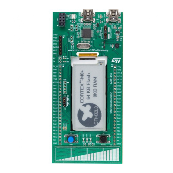
It offers everything required for beginners and experienced users to get started quickly and develop applications easily. Based on an STM32L053C8T6, it includes an ST-LINK/V2-1 embedded debug tool interface, linear touch sensor, IDD current measurement, 2.04” E-paper display, NFC connector for PLUG-CR95HF-B board, LEDs, pushbuttons and a USB Mini-B connector. -
Page 37: Figure 40. Stm32L0538-Disco Board Schematics
AN5105 Discovery board: STM32L0538-DISCO Figure 40. STM32L0538-DISCO board schematics AN5105 - Rev 1 page 37/52... -
Page 38: Stm32L0538-Disco Tsc Group And Sensor Activation
AN5105 Discovery board: STM32L0538-DISCO 7.3.2 STM32L0538-DISCO TSC group and sensor activation To activate the TSC group, sampling capacitors and sensor channels follows the below steps: • Activate TSC according schematics information. • You can deactivate unrelevant peripheral like USB, SPI, NCF(L0), EPaper(L0), MFX(L0) SWD peripheral must be set according to Figure Figure 41. -
Page 39: Stm32L0538-Disco Clock Tree
AN5105 Discovery board: STM32L0538-DISCO Figure 43 shows the results obtained. Figure 43. Pinout overview 7.3.3 STM32L0538-DISCO clock tree It uses the default clock tree setting. Figure 44. Clock configuration AN5105 - Rev 1 page 39/52... -
Page 40: Stm32L0538-Disco Touchsensing Library
AN5105 Discovery board: STM32L0538-DISCO 7.3.4 STM32L0538-DISCO touchsensing library To activate the TLS usage, switch on TOUCHSENSING box configuration. Figure 45. TOUCHSENSING box configuration Select 3 channels Linear slider and assign dedicated Gx_IOy (see previous chapter or schematics for details). For training purpose, the user can: •... -
Page 41: Figure 47. Stm32L0538-Disco Sensor Selection Step2
AN5105 Discovery board: STM32L0538-DISCO Figure 47. STM32L0538-DISCO sensor selection step2 Figure 48. STM32L0538-DISCO sensor selection step3 AN5105 - Rev 1 page 41/52... -
Page 42: Figure 49. Stm32L0538-Disco Sensor Selection Step4
AN5105 Discovery board: STM32L0538-DISCO Figure 49. STM32L0538-DISCO sensor selection step4 Figure 50. STM32L0538-DISCO sensor selection step5 AN5105 - Rev 1 page 42/52... -
Page 43: Stm32L0538-Disco Software Project Generation
AN5105 Discovery board: STM32L0538-DISCO 7.3.5 STM32L0538-DISCO software project generation Now, it is possible to generate the complete software project based on TSC HAL and TSL. See details in Figure 51 Figure Figure 51. STM32L0538-DISCO software generation step1 Figure 52. STM32L0538-DISCO software generation step2 AN5105 - Rev 1 page 43/52... - Page 44 AN5105 Discovery board: STM32L0538-DISCO Figure 53. STM32L0538-DISCO complete project overview Figure 54. STM32L0538-DISCO IDE workspace Figure 55. SWD settings AN5105 - Rev 1 page 44/52...
-
Page 45: Stm32L0538-Disco Software Basic Algorythm
AN5105 Discovery board: STM32L0538-DISCO 7.3.6 STM32L0538-DISCO software basic algorithm Below is showed an example to show keys usage instead of slider usage. • Open your IDE and in main.c file add the following lines: /* USER CODE BEGIN 3 */ extern TSL_TouchKey_T MyTKeys[];... -
Page 46: Revision History
AN5105 Revision history Table 22. Document revision history Date Version Changes 19-Sep-2018 Initial release. AN5105 - Rev 1 page 46/52... -
Page 47: Table Of Contents
AN5105 Contents Contents General information ............. . . 2 Terminology and principle . - Page 48 AN5105 Contents Discovery board: STM32F072B-DISCO......... . . 25 7.2.1 STM32F072B-DISCO board selection .
- Page 49 AN5105 List of tables List of tables Table 1. Change transfer principle documentation ........... 4 Table 2.
- Page 50 AN5105 List of figures List of figures Figure 1. Change transfer principle ............. 4 Figure 2.
- Page 51 AN5105 List of figures Figure 53. STM32L0538-DISCO complete project overview..........44 Figure 54.
- Page 52 ST’s terms and conditions of sale in place at the time of order acknowledgement. Purchasers are solely responsible for the choice, selection, and use of ST products and ST assumes no liability for application assistance or the design of Purchasers’...
Need help?
Do you have a question about the STM32F0 Series and is the answer not in the manual?
Questions and answers