
Subscribe to Our Youtube Channel
Related Manuals for KYLAND Technology SICOM3448G-Port-HV-HV


Summary of Contents for KYLAND Technology SICOM3448G-Port-HV-HV
- Page 1 SICOM3448G Series Industrial Ethernet Switch Hardware Installation Manual Publication Date: Jan. 2017 Version: V1.0 No.:...
- Page 2 SICOM3448G Industrial Ethernet Switch Hardware Installation Manual Disclaimer: Kyland Technology Co., Ltd. tries to keep the content of this manual as accurate and as updated as possible. This document is not guaranteed to be error-free, and we reserve the right to amend it without notice to users.
- Page 3 Notice for Safety Operation The product performs reliably as long as it is used according to the guidance. Artificial damage or destruction of the device should be avoided. Before using the device, read this manual carefully for personal and equipment safety. Please keep the manual for further reference.
- Page 4 Do not disassemble the device by yourself. When an anomaly occurs, contact our sales or technical support personnel. If any part is lost, contact our sales or technical support personnel to purchase the substitute. Do not purchase parts from other channels. ...
-
Page 5: Table Of Contents
Contents 1 Product Overview ......................1 2 Structure and Interface ...................... 2 2.1 Front Panel ......................... 2 2.2 Rear Panel ........................3 3 Switch Installation ......................4 3.1 Dimension Drawing ..................... 4 3.2 Mounting Modes and Steps ..................5 4 Cable Connection ......................8 4.1 10/100/1000Base-T(X) Ethernet Port ................ -
Page 6: Product Overview
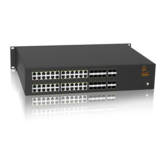
The series switches are applicable to harsh industrial environments. The series switches support 19 inch 2U rack mounting by front/rear panel. The specific configuration of the product is shown in the following table. Table 1 Configuration SICOM3448G-Port-HV-HV Models SICOM3448G-C-Port-HV-HV Code definition Code option Indicating three anti-coating 4X8G16GE,4X8G24GX16GE,4X20G28GE... -
Page 7: Structure And Interface
Structure and Interface 2 Structure and Interface Caution: It is recommended to purchase the port dustproof shield (optional) to keep ports clean and ensure switch performance. 2.1 Front Panel Figure 1 Front Panel Table 2 Description of Front Panel Identifier Description Alarm Alarm LED... -
Page 8: Rear Panel
Structure and Interface 2.2 Rear Panel Figure 2 Rear Panel Table 3 Description of Rear Panel Panel identification Description GE(1-16) Sixteen 10/100/1000Base-T(X) Ethernet ports GE/GX(17-24) Eight 1000Base-X,10/100/1000Base-T(X)Combo ports XG(1-4) Four 10 Gigabit SFP + ports FAULT Alarm terminal PWR1/PWR2 Power terminal Ground terminal GX(25-48) Twenty-four 1000Base-X, 10/100/1000Base-T(X) SFP ports... -
Page 9: Switch Installation
Switch Installation 3 Switch Installation 3.1 Dimension Drawing Figure 3 Dimension Drawing (unit: mm) Caution: As part of the heat dissipation system, the switch housing becomes hot during operation. Please use caution when coming in contact and avoid covering the switch housing when the switch is running. -
Page 10: Mounting Modes And Steps
Switch Installation 3.2 Mounting Modes and Steps The series switches support rack mounting by front/rear panel. The following uses mounting by front panel as an example to describe mounting steps. The steps for mounting by rear panel are similar to those for mounting by front panel. Before installation, make sure that the following requirements are met. - Page 11 Switch Installation install the mounting brackets, other small screw holes (M3) are used to fasten gaskets. If there are screws inserted in screw holes (M4), remove the screws and keep them for future use. As shown in the following figure, use three screws to secure two mounting brackets to the switch respectively.
- Page 12 Switch Installation Dismounting Step 1: Remove the four screws and supporting captive nuts securing the mounting brackets to the rack posts. Step 2: Remove the switch from the rack posts. Then unscrew the mounting brackets to complete dismounting.
-
Page 13: Cable Connection
Cable Connection 4 Cable Connection 4.1 10/100/1000Base-T(X) Ethernet Port 10/100/1000Base-T(X) Ethernet port is equipped with RJ45 connector. The port is self-adaptive. It can automatically configure itself to work in 10M, 100M, or 1000M state, full or half duplex mode. The port can also adapt to MDI or MDI-X connection automatically. You can connect the port to a terminal or network device with a straight-through or cross-over cable. -
Page 14: 1000Base-X, 10/100/1000Base-T(X) Sfp Slot
Cable Connection Wiring Sequence Figure 8 Connection Using Straight-through/Cross-over Cable Note: The color of the cable for RJ45 connector meets the 568B standard: 1-orange and white, 2-orange, 3-green and white, 4-blue, 5-blue and white, 6-green, 7-brown and white, and 8-brown. - Page 15 Cable Connection Figure 9 Gigabit SFP Optical Module Gigabit SFP optical module is equipped with LC connector, and each port consists of a TX (transmit) port and an RX (receive) port. To enable communication between Device A and Device B, connect the TX (transmit) port of Device A to the RX (receive) port of Device B, and the RX (receive) port of Device A to the TX (transmit) port of Device B.
-
Page 16: 1000Base-X, 10/100/1000Base-T(X) Combo Port
Cable Connection incorrect connection of the TX and RX ports. In this case, swop the two connectors in the one end of the optical fiber. Caution: The device uses laser to transmit signals in fibers. The laser meets the requirements of level 1 laser products. -
Page 17: 10Gbase-X Sfp+ Port
Cable Connection 4.4 10GBase-X SFP+ port 10GBase-X SFP+ slot (10GBase-X SFP+ slot) requires an SFP+ optical module to enable data transmission. The following table lists the 10GBase-X SFP+ optical modules (optional) supported by the series switches. Table 7 SFP+ optical module Central Transmission Model... -
Page 18: Grounding
Cable Connection Figure 13 Wiring Sequence of DB9-RJ45 Console Cable Table 8 Pin Definitions of DB9 Port (9-Pin Serial Port) and RJ45 Port (Console Port) DB9 Port (9-Pin Serial Port) RJ45 Port (Console Port) Signal Signal RXD (Receive data) TXD (Transmit data) TXD (Transmit data) RXD (Receive data) GND (Grounding) -
Page 19: Power Terminal Block
Cable Connection 4.7 Power Terminal Block There is a power terminal block on the rear panel of the switch. You need to connect the power cable to the terminal block to provide power for the switch. The device supports single (PWR1) and redundant (PWR1 and PWR2) power supply with a 5-pin 5.08mm-spacing plug-in terminal block. -
Page 20: Alarm Terminal Block
Cable Connection Step 3: Insert the power cable into the power terminal block according to Table 9 to fix the power cable. Step 4: Insert the terminal with the connected cable into the terminal block on the device. Step 5: Connect one end of the power cable to an external power supply system (with the allowed power range). - Page 21 Cable Connection Max Switch Power: 60W Maximum dielectric voltage withstand: 2KV Note: Pin 1 and pin 2 are normally-open contacts; pin 2 and pin 3 are normally-closed contacts. When the switch works properly, pin 1 and pin 2 are closed, pin 2 and pin 3 are open; when an alarm occurs, pin 1 and pin 2 are open;...
-
Page 22: Leds
LEDs 5 LEDs Table 10 Front Panel LEDs State Description Power 1 is connected and operates properly. Power 1 LED- PWR1 Power 1 is not connected or operates abnormally. Power 2 is connected and operates properly. Power 2 LED- PWR2 Power 2 is not connected or operates abnormally. - Page 23 LEDs Yellow 1000M working state(1000Base-TX) blinking Ongoing network activities Green 10/100M working state (10/100Base-T(X)) and blinking Ongoing network activities No effective port connection LED 1 and LED 2 indicate the status of the lower gigabit SFP slot, while LED 3 and LED 4 indicate the status of the upper gigabit SFP slot.
-
Page 24: Switch Access
Switch Access 6 Switch Access You can access the switch in any of the following ways: 6.1 Access through Console Port Step 1: Connect the console port of the switch to the 9-pin serial port of a PC with the delivered DB9-RJ45 console cable. - Page 25 Switch Access Figure 17 Selecting the Communication Port in Use Note: To confirm the communication port in use, right-click [My Computer] and click [Property]→ [Hardware]→[Device Manager]→[Port] to view the communication port. Step 5: Set port parameters (Bits per second: 115200, Data bits: 8, Parity: None, Stop bits: 1, and Flow control: None), as shown in Figure 18.
-
Page 26: Access Through Telnet
Switch Access Step 6: Click OK to enter the switch CLI. Then you can run the following commands to perform operations. Table 12 CLI Commands View Command Description User view SWITCH>enable Enter the management view. Management view SWITCH#show interface Query the IP address of the switch. Management view SWITCH#show version Query the version of the switch. - Page 27 Switch Access cable. Step 2: Enter the IP address of the switch in the address box of the browser. The user login interface is displayed. You can log in to the Web UI by default user name "admin" and password "123". Note: ...
-
Page 28: Basic Features And Specifications
Basic Features and Specifications 7 Basic Features and Specifications Power Requirements Power Identifier Rated Voltage Range Maximum Voltage Range HV (220AC/DCW) 100-240VAC, 50/60Hz; 110-220VDC 85-264VAC/77-300VDC Power terminal 5-pin 5.08mm-spacing plug-in terminal block Rated Power Consumption Rated Power Consumption 70W (MAX) Physical Characteristics Housing Metal, fanless... - Page 29 Customer Service Hotline: 010-88796676 FAX: 010-88796678 Website: http://www.kyland.com.cn Email: services@kyland.com.cn For more information about KYLAND products, please visit our website: http://www.kyland.com.cn http://www.kyland.com...
Need help?
Do you have a question about the SICOM3448G-Port-HV-HV and is the answer not in the manual?
Questions and answers