Table of Contents
Advertisement
Quick Links
Download this manual
See also:
User Manual
Advertisement
Table of Contents

Subscribe to Our Youtube Channel
Related Manuals for KYLAND Technology SICOM3000


Summary of Contents for KYLAND Technology SICOM3000
- Page 1 SICOM3000 Industrial Ethernet Switch Hardware Installation Manual Publication Data: Jun. 2013 Version: V1.0 No.: 1.12.02.
- Page 2 SICOM3000 Industrial Ethernet Switch Hardware Installation Manual Disclaimer: Kyland Technology Co., Ltd. tries to keep the content of this manual as accurate and as updated as possible. This document is not guaranteed to be error-free, and we reserve the right to amend it without notice to users.
- Page 3 Notice for Safety Operation The product performs reliably as long as it is used accord- ing to the guidance. Artificial damage or destruction of the device should be avoided. Before using the device, read this notice carefully for personal and equipment safety. Please keep the manual for further reference.
- Page 4 ● Do not operate the device or connect or disconnect cables during an electrical storm. ● Use compatible connectors and cables. If you are not sure, contact our sales or technical support personnel for confirmation. ● Do not disassemble the device by yourself. When an anomaly occurs, contact our sales or technical support personnel.
-
Page 5: Table Of Contents
Contents 1 Product Overview 2 Structure and Interface 2.1 Front Panel 2.2 Top Panel 3 Mounting 3.1 Dimension Drawing 3.2 Mounting Modes and Steps 3.2.1 Mounting 3.2.2 Panel Mounting 4 Connection 4.1 10/100Base-T(X) Ethernet Port 4.2 100Base-FX Ethernet Port 4.3 1000Base-X, 10/100/1000Base-T(X) SFP Slot 4.3.1 Gigabit SFP Optical Module 4.3.2 Gigabit SFP Electrical Module 4.4 Console Port... -
Page 7: Product Overview
Product Overview 1 Product Overview SICOM3000 includes a series of industrial Ethernet switches applied in the wind power, distribution network automation, subway PIS and AFC, power SCADA, sewage treatment, highway, metallurgy, hydroelectric power, photovoltaic generation, subway CBTC, plant automation, intelligent transportation, and many other industries.SICOM3000 is... -
Page 8: Structure And Interface
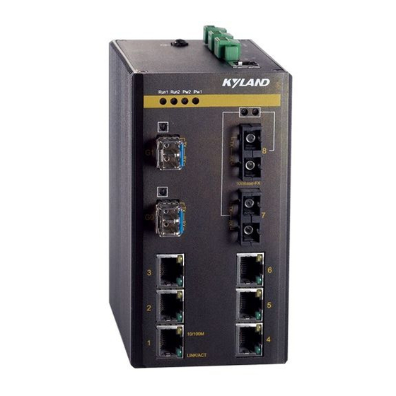
2 Structure and Interface Caution: It is recommended to purchase the port dustproof shield (optional) to keep ports clean and ensure switch performance. 2.1 Front Panel Front Panel of SICOM3000-2GX-2S/M-6T (1)(2)(3)(4) (10) (11) Speed Link/ACT Figure 1 Front Panel of SICOM3000-2GX-2S/M-6T... - Page 9 Structure and Interface Table 2 Description of the Front Panel of SICOM3000-2GX-2S/M-6T Identifier Description PWR1 Power 1 LED PWR2 Power 2 LED Running LED Alarm Alarm LED Gigabit SFP slot (G2) and its connection status LED Gigabit SFP slot (G1) and its connection...
- Page 10 Structure and Interface Front Panel of SICOM3000-2GX-8T (1)(2)(3)(4) Speed Link/ACT Figure 2 Front Panel of SICOM3000-2GX-8T...
- Page 11 Structure and Interface Table 3 Description of the Front Panel of SICOM3000-2GX-8T No. Identifier Description PWR1 Power 1 LED PWR2 Power 2 LED Running LED Alarm Alarm LED Gigabit SFP slot (G2) and its connection status LED Gigabit SFP slot (G1) and its connection...
-
Page 12: Top Panel
Structure and Interface 2.2 Top Panel PWR1 PWR2 Console +/L -/N -/N +/L FAULT Figure 3 Top Panel Table 4 Description of the Top Panel No. Identifier Description PWR1 PWR2 Power terminal block +/L -/N -/N +/L Alarm terminal block FAULT Console Console port... -
Page 13: Mounting
Mounting 3 Mounting 3.1 Dimension Drawing Figure 4 Dimensions for DIN-Rail Mounting (unit:mm) Figure 5 Dimensions for Panel Mounting (unit:mm) Caution: As part of the heat dissipation system, the switch housing becomes hot during operation. Please use caution when coming in contact and avoid covering the switch housing when the switch is running. -
Page 14: Mounting Modes And Steps
Mounting 3.2 Mounting Modes and Steps The series switches support DIN-rail and panel mounting. Before installation, make sure that the following requirements are met. 1) Environment:temperature (-40 to 85 ), ambient relative humidity (5% to 95%, non-condensing) 2) Power requirement:The power input is within the voltage range of the switch. - Page 15 Mounting DIN-Rail Dismounting Step 1: Insert the head of a screwdriver into the opening of the spring locking piece at the bottom from the left. Lift the handle of the screwdriver to open the spring locking piece of the connecting seat, as shown on the left of the following figure.
-
Page 16: Panel Mounting
Mounting 3.2.2 Panel Mounting Note: Purchase the plate (optional) for panel mounting. Panel Mounting Step 1:Use screws to secure the plate for panel mounting to the rear panel of the device. Step 2:Select the mounting position (on a wall or inner wall of a cabinet) for the device and guarantee adequate space and heat dissipation (dimensions:75mm×140mm×123mm). - Page 17 Mounting Panel Dismounting Step 1:Loosen the four screws with a screwdriver. Pull the device upward until the four screws are in the Ф6.5 positions in the following figure. Then remove the plate for panel mounting from the four screws to detach the device from the wall or inner wall of the cabinet.
-
Page 18: Connection
Connection 4 Connection 4.1 10/100Base-T(X) Ethernet Port 10/100Base-T(X) Ethernet port is equipped with RJ45 connector. The port is self-adaptive. It can automatically configure itself to work in 10M or 100M state, full or half duplex mode. The port can also adapt to MDI or MDI-X connection automatically. - Page 19 Connection Wiring Sequence RJ45 connector RJ45 connector Straight-through cable Wiring sequence Cross-over cable Wiring sequence Figure 11 Connection Using Straight-through/Cross-over Cable Note: The color of the cable for RJ45 connector meets the 568B standard:1-orange and white, 2-orange, 3-green and white, 4-blue, 5-blue and white, 6-green, 7-brown and white, and 8-brown.
-
Page 20: 100Base-Fx Ethernet Port
Connection 4.2 100Base-FX Ethernet Port 100Base-FX Ethernet port is equipped with FC/ST/SC connector, and each port consists of TX (transmit) port and RX (receive) port. To enable data transmission between Device A and Device B, connect the TX port of Device A to the RX port of Device B, and the RX port of Device A to the TX port of Device B. -
Page 21: 1000Base-X, 10/100/1000Base-T(X) Sfp Slot
Connection 4.3 1000Base-X, 10/100/1000Base-T(X) SFP Slot 1000Base-X, 10/100/1000Base-T(X) SFP slot (gigabit SFP slot) requires an SFP optical/electrical module to enable data transmis- sion. The following table lists the gigabit SFP optical/electrical modules (optional) supported by the series switches. Table 6 Gigabit SFP Optical/Electrical Modules... -
Page 22: Gigabit Sfp Optical Module
Connection 4.3.1 Gigabit SFP Optical Module Figure 13 Gigabit SFP Optical Module An SFP optical module is equipped with LC connector, and each port consists of a TX (transmit) port and an RX (receive) port. To enable communication between Device A and Device B, connect the TX port of Device A to the RX port of Device B, and the RX port of Device A to the TX port of Device B, as shown in the following figure. - Page 23 Connection How to Connect the SFP Optical Module Insert the SFP optical module into the SFP slot in the switch, and then insert the fibers into the TX port and RX port of the SFP module. SFP slot SFP optical module Optical fiber Figure 15 Connecting the SFP Optical Module Identify the RX port and TX port of an SFP optical module:...
-
Page 24: Gigabit Sfp Electrical Module
Connection 4.3.2 Gigabit SFP Electrical Module Figure 16 Gigabit SFP Electrical Module How to Connect the SFP Electrical Module Insert the SFP electrical module into the SFP slot in the switch, and then insert the RJ45 connector of the twisted pair into the SFP module. SFP slot SFP Electrical module RJ45 connector... -
Page 25: Console Port
Connection 4.4 Console Port Connect the 9-pin serial port of a PC to the console port of the switch with a DB9-RJ45 console cable. Then you can configure, maintain, and manage the switch by running Hyper Terminal in Windows OS of a computer. -
Page 26: Grounding
Connection Table 7 Pin Definitions of DB9 Port (9-Pin Serial Port) and RJ45 Port (Console Port) DB9 Port (9-Pin Serial Port) RJ45 Port (Console Port) Pin Signal Signal RXD (Receive data) TXD (Transmit data) TXD (Transmit data) RXD (Receive data) GND (Grounding) GND (Grounding) 4.5 Grounding... -
Page 27: Power Terminal Block
Connection 4.6 Power Terminal Block You need to connect the power wires to the terminal block to provide power to the device. The device supports single (PWR1) and redun- dant (PWR1 and PWR2) power supply (as listed in Table 1) with a 5-pin 5.08mm-spacing plug-in terminal block. - Page 28 Connection The following table lists the pin definitions of the 5-pin 5.08mm-spacing plug-in terminal block. Table 8 Pin Definitions of 5-Pin 5.08mm-Spacing Plug-in Terminal Block Signal DC Definition AC Definition PWR1: + PWR1: L PWR1: - PWR1: N PGND PGND PWR2: - PWR2: N PWR2: +...
- Page 29 Connection PWR2:-/N PGND PWR1:-/N PWR2:+/L PWR1:+/L Plug Socket Figure 22 Connection of 5-Pin 5.08mm-Spacing Plug-in Terminal Block Caution: The switch supports 12DCW, 24DCW, and 220AC/DCW power input (as listed in Table 1). Before connecting the device to power supply, make sure that the power input meets the power requirement.
-
Page 30: Alarm Terminal Block
Connection 4.7 Alarm Terminal Block The device provides a 3-pin 5.08mm-spacing plug-in terminal block for alarm output or input. 3 2 1 FAULT Figure 23 Alarm Terminal Block (socket) Alarm Output The 3-pin 5.08-spacing plug-in terminal blocks of the following models are used for alarm output. - Page 31 Connection Alarm Input The 3-pin 5.08-spacing plug-in terminal blocks of the following models are used for alarm input. The pins of the alarm terminal block are redefined, as listed in the following table. The switch receives external alarm signals from the terminal block and outputs corresponding alarms.
-
Page 32: Leds
LEDs 5 LEDs Table 11 Front Panel LEDs Speed(yellow) Connection status (green) -
Page 33: Switch Access
Switch Access 6 Switch Access You can access the switch in any of the following ways: 6.1 Access through Console Port Step 1: Connect the console port of the switch to the 9-pin serial port of a PC with the delivered DB9-RJ45 console cable. Step 2: Open Hyper Terminal in Windows OS. - Page 34 Switch Access Step 4: Connect the communication port in use, as shown in the following figure. Figure 25 Selecting a Serial Port Note: To confirm the communication port in use, right-click [My Computer] and select [Property]. Click [Hardware] → [Device Manager] →...
- Page 35 Switch Access Step 5:Set port parameters (Bits per second: 115200, Data bits:8, Parity:None, Stop bits:1, and Flow control:None), as shown in the following figure. Figure 26 Setting Port Parameters Step 6:Click OK to enter the switch CLI. Then the following commands can be used to perform operations.
-
Page 36: Access Through Telnet
Switch Access 6.2 Access through Telnet Step 1:Connect the network port of a PC to the Ethernet port of the switch with a network cable. Step 2:On the Windows desktop, click Start and Run. The Run dialog box is displayed. Enter "telnet IP address". For example, if the IP address of the device is 192.168.0.2 (default IP address of a Kyland switch), enter "telnet 192.168.0.2"... -
Page 37: Basic Features And Specifications
Basic Features and Specifications 7 Basic Features and Specifications... - Page 40 FAX: +86-10-88796678 Website: http://www.kyland.com Email: support@kyland.com For more information about KYLAND products, please visit our website: http://www.kyland.com...
Need help?
Do you have a question about the SICOM3000 and is the answer not in the manual?
Questions and answers