Table of Contents
Advertisement
Quick Links
Advertisement
Table of Contents

Related Manuals for Fanvil i23


Summary of Contents for Fanvil i23
- Page 1 [键入文字] IP Voice Access User Manual Wall mounted In-wall 1 / 59...
- Page 2 [键入文字] Document VER Firmware VER Explanation Time V1.0 2.3.1028.434 Initial issue 20151209 V.2.0 2.3.1028.434 Increase the interface parameters, modify the company 20171027 address, increase the QIG IP scanning tool download address 2 / 59...
- Page 3 [键入文字] Safety Notices 1. Please use the specified power adapter. If you need to use the power adapter provided by other manufacturers under special circumstances, please make sure that the voltage and current provided is in accordance with the requirements of this product, meanwhile, please use the safety certificated products, otherwise may cause fire or get an electric shock.
-
Page 4: Table Of Contents
[键入文字] Directory PRODUCT INTRODUCTION ......................6 1. A ......................6 PPEARANCE OF THE PRODUCT ............................ 7 DESCRIPTION B. START USING ............................ 8 1. C ........................8 ONFIRM THE CONNECTION 1) Power port ..........................8 2) Electric-lock and indoor switch port ................... 8 3) Driving mode of electric-lock(Default in active mode) .............. - Page 5 [键入文字] VOIP ............................. 26 a) SIP ............................26 b) STUN ............................ 29 INTERCOM ........................... 31 a) AUDIO ..........................31 b) FEATURE ..........................32 c) MCAST ..........................34 d) Action URL ........................... 37 DOOR PHONE ........................37 a) FUNCTION KEY ........................37 b) DOOR PHONE ........................
-
Page 6: Product Introduction
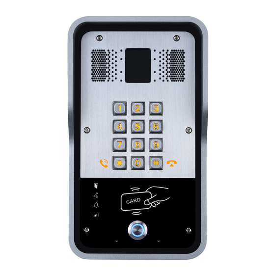
[键入文字] A. Product introduction i23 voice access is a full digital network door phone,with its core part adopts mature VoIP solution(Broadcom chip), stable and reliable performance, hands-free adopting digital full-duplex mode, voice loud and clear, generous appearance, solid durable, easy for installation, comfortable keypad and low power consumption. -
Page 7: Description
[键入文字] 2. description Buttons and icons Description Function Numeric keyboard Input password to open the door or to call. Can be set to a variety of functions, in order to programmable keys meet the needs of different occasions induction zone RFID induction area Door unlocking: On Lock Status... -
Page 8: Start Using
[键入文字] B. Start Using Before you start to use the equipment, please make the following installation: 1. Confirm the connection Confirm whether the equipment of the power cord, network cable, electric lock control line connection and the boot-up is normal. (Check the network state of light) 1) Power port Power supply ways: 12v/DC or POE. -
Page 9: Wiring Instructions
[键入文字] 4) Wiring instructions NO: Normally Open Contact. COM: Common Contact. NC: Normally Close Contact. Driving Mode Electric lock Jumper port Connections Active Passive √ √ √ √ √ √ √ √ √ √ 9 / 59... -
Page 10: Quick Setting
Press and hold “#” key for 3 seconds and the door phone will report the IP address by voice, or use the "iDoorPhoneNetworkScanner.exe " software to find the IP address of the device. (Download address http://download.fanvil.com/tool/iDoorPhoneNetworkScanner.exe Note: when power on, 30s waiting is needed for device running. Log on to the WEB device configuration. -
Page 11: Basic Operation
[键入文字] C. Basic operation 1. Answer a call When a call comes in, the device will answer automatically. If you cancel auto answer feature and set auto answer time, you will hear the bell ring at the set time and the device will auto answer after a timeout. -
Page 12: Page Settings
[键入文字] If access code is input correctly, the device will play sirens sound to prompt access control and the remote user, while input error by low-frequency short chirp. Password input successfully followed by high-frequency sirens sound, while input error is followed by high-frequency short chirp. -
Page 13: Configuration Via Web
[键入文字] 3. Configuration via WEB (1) BASIC a) STATUS Status Field Name Explanation Shows the configuration information for WAN and LAN port, including connection Network mode of WAN port (Static, DHCP, PPPoE),MAC address, IP address of WAN port and LAN port, DHCP server, status for LAN port (ENABLED or DISABLED). -
Page 14: B) Wizard
[键入文字] b) WIZARD Wizard Field Name Explanation Select the appropriate network mode. The equipment supports three network modes: Static IP mode The parameters of a Static IP connection must be provided by your ISP. In this mode, network parameter information will be obtained automatically from a DHCP mode DHCP server. -
Page 15: C) Language
[键入文字] c) LANGUAGE Set the current language. d) TIME&DATE Set the time zone and SNTP (Simple Network Time Protocol) server on this page. Daylight Saving Time configuration and Manual Time and Date entry can also be done in this page. 15 / 59... - Page 16 [键入文字] Time&Date Field Name Explanation System Current Time Display the current time Simple Network Time Protocol (SNTP) Settings Enable SNTP Enable or Disable SNTP Enable DHCP If this is enabled, equipment will synchronize time with DHCP server Time Primary Server IP address of Primary SNTP Server Secondary IP address of Secondary SNTP Server...
-
Page 17: Network
[键入文字] (2) NETWORK a) WAN Field Name Explanation WAN Status Active IP The current IP address of the equipment address Current subnet The current Subnet Mask mask Current IP The current Gateway IP address gateway MAC address The MAC address of the equipment MAC Timestamp Get the MAC address of time. - Page 18 [键入文字] Field Name Explanation DHCP Network parameters are provided automatically by a DHCP server. PPPoE Account and Password must be input manually. These are provided by your ISP. If Static IP is chosen, the screen below will appear. Enter values provided by the ISP. After entering the new settings, click the APPLY button.
-
Page 19: B) Lan
[键入文字] b) LAN Field Name Explanation IP Address LAN static IP If Bridge Mode is activated, the equipment will not provide an IP address for the LAN Enable bridge port. Instead, the LAN and WAN will be part of the same network. If this is activated, mode clicking Apply, will cause the equipment reboot. - Page 20 [键入文字] Chart 2 shows an example with two VLANs indicated by red and blue. In this example, frames broadcast from Port 1 will only go to Port 2 since Ports 3 and 4 are in a different VLAN. VLANs can be used to divide a network by restricting the transmission of broadcast frames.
-
Page 21: D) Web Filter
[键入文字] QoS&VLAN Field Name Explanation Link Layer Discovery Protocol (LLDP) Settings Enable LLDP Enable or Disable Link Layer Discovery Protocol (LLDP) Enables the telephone to synchronize its VLAN data with the Network Switch. Enable Learning The telephone will automatically synchronize DSCP, 802.1p, and VLAN ID Function values even if these values differ from those provided by the LLDP server. -
Page 22: E) Firewall
[键入文字] Web filter The Web filter is used to limit access to the equipment. When the web filter is enabled, only the IP addresses between the start IP and end IP can access the equipment. Web Filter Table Web page access allows display the IP network list. Web Filter Table Settings Beginning and Ending IP Address for MMI Filter, Click add this filter range to the Web Filter Table. -
Page 23: F) Vpn
[键入文字] Field Name Explanation Firewall Settings Input / Output Specify if the current rule is input or output. Deny/Permit Specify if the current rule is Deny or Permit. Protocol Filter protocol type (TCP/ UDP/ ICMP/ IP) Port Range Set the filter Port range Set source address. - Page 24 [键入文字] Field Name Explanation Virtual Private Network (VPN) Status VPN IP Shows the current VPN IP address. VPN Mode Enable VPN Enable/Disable VPN. L2TP Select Layer 2 Tunneling Protocol Select OpenVPN Protocol. (Only one protocol may be activated. After the selection is Open VPN made, the configuration should be saved and the phone be rebooted.) Layer 2 Tunneling Protocol (L2TP)
-
Page 25: G) Security
[键入文字] g) SECURITY Field Name Explanation Update Security Select the security file to be updated. Click the Update button to update. File Delete Security Select the security file to be deleted. Click the Delete button to Delete. File SIP TLS Files Show SIP TLS authentication certificate. -
Page 26: Voip
[键入文字] (3) VOIP a) SIP Configure a SIP server on this page. 26 / 59... - Page 27 [键入文字] Field Name Explanation Basic Settings (Choose the SIP line to configured) Shows registration status. If the registration is successful done,it will display “has Status been registered”, otherwise will display “not registered”.The wrong password will display “403 errors” and account number failure will display “timeout”. Server Address SIP server IP address or URI.
- Page 28 [键入文字] Field Name Explanation SIP Encryption Enable/Disable SIP Encryption. Enable Session If enabled, this will refresh the SIP session timer per RFC4028. Timer Registration SIP re-registration time. Default is 60 seconds. If the server requests a different time, Expires the phone will change to that value. Session Timeout Refresh interval if Session Timer is enabled.
-
Page 29: B) Stun
[键入文字] Field Name Explanation Enable DNS SRV Enables use of DNS SRV records Use VPN Enable SIP use VPN for every line individually, not all of them Transport Configuration using the transport protocol, TCP, TLS or UDP, the default is UDP. Protocol SIP Global Settings Enable Strict Branch - The value of the branch must be after”z9hG4bK”... - Page 30 [键入文字] STUN Field Name Explanation STUN NAT Traversal Shows whether or not STUN NAT Traversal was successful. Server Address STUN Server IP address Server Port STUN Server Port – Default is 3478. STUN blinding period – STUN packets are sent at this interval to keep the NAT Binding Period mapping active.
-
Page 31: Intercom
[键入文字] (4) INTERCOM a) AUDIO This page configures audio parameters such as voice codec, speak volume, mic volume and ringer volume. Field Name Explanation Audio Settings First Codec The first codec choice: G.711A/U, G.722, G.723.1, G.726-32, G.729AB Second Codec The second codec choice: G.711A/U, G.722, G.723.1, G.726-32, G.729AB, None Third Codec The third codec choice: G.711A/U, G.722, G.723.1, G.726-32, G.729AB, None Fourth Codec... -
Page 32: B) Feature
[键入文字] Field Name Explanation Talk Volume Settings SPK Output Set the speaker calls the volume level. Volume MIC Input Set the MIC calls the volume level. Volume Media Volume Settings Broadcast Set the broadcast the output volume level. Output Volume Signal Tone Set the audio signal the output volume level. - Page 33 [键入文字] Field Name Explanation Enable Intercom If enabled, mutes incoming calls during an intercom call. Mute Enable Intercom If enabled, plays intercom ring tone to alert to an intercom call. Tone Enable Auto Enable Auto Answer function Answer Auto Answer Set Auto Answer Timeout Timeout No Answer...
-
Page 34: C) Mcast
[键入文字] c) MCAST It is easy and convenient to use multicast function to send notice to each member of the multicast via setting the multicast key on the device and sending multicast RTP stream to pre-configured multicast address. By configuring monitoring multicast address on the device, monitor and play the RTP stream which sent by the multicast address. - Page 35 [键入文字] The options are as follows: 1-10: To definite the priority of the common calls, 1 is the top level while 10 is the lowest Disable: ignore all incoming multicast RTP stream Enable the page priority: Page priority determines the device how to deal with the new receiving multicast RTP stream when it is in multicast session currently.
- Page 36 [键入文字] Purple part (host: port) It is a set of addresses and ports to listen, separated by a colon. Pink part (index / priority) Multicast is a sign of listening, but also the monitoring multicast priority. The smaller number refers to higher priority.
-
Page 37: D) Action Url
[键入文字] d) Action URL Action URL Settings URL for various actions performed by the phone. These actions are recorded and sent as xml files to the server. Sample format is http://InternalServer /FileName.xml (5) DOOR PHONE a) FUNCTION KEY 37 / 59... - Page 38 [键入文字] Key Event Settings Set the key type to the Key Event. DSS key type Subtype Usage None Not responding Dial Dial function Key Event Release End calls Identify key Handfree The hand-free key(with hook dial, hang up) Hot key Settings Enter the phone number in the input box, when you press the shortcut key, equipment will dial set telephone number.
- Page 39 [键入文字] Multicast Settings Multicast function is launched will voice messages sent to set the multicast address, all equipment to monitor the group multicast address can receive sponsors speech information, etc. Using multicast functionality can be simple and convenient to send notice to each member in the multicast. Through the DSS Key configuration multicast calling WEB is as follows: DSS key type Number...
-
Page 40: B) Door Phone
The call will be ended automatically when time up. 120 seconds Remote Remote door unlocking password. Password Local Local door unlocking password via keypad, the default password 6789 Password length is 4. i23 IP door Description Device description displayed on IP scanning tool software. phone 40 / 59... - Page 41 [键入文字] Field Name Explanation Initial Value Enable Access Table: enter <Access Code> for opening door during Enable Access calls. Enable Table Disable Access Table: enter <Remote Password> for opening door during calls. <Primary /Secondary>mode allow system to call primary extension first, if there were no answer, it would cancel the call and then call Hot Key Dialed secondary extension automatically.
-
Page 42: C) Door Card
[键入文字] Field Name Explanation Tamper Alarm Settings Tamper Alarm When the selection is enabled, the tamper detection enabled Reset Directly stop the alarm from equipment in the Webpage Alarm When detected someone tampering the equipment, will be sent alarm to the command corresponding server Reset... - Page 43 [键入文字] Door Card Field Name Explanation Door Card Table Index The serial number of has been issuer cards. Name The name of has been issuer cards. The card number of has been issuer cards. (Note: The card is not registered in the remote access list is unable to open the door.) Issuing Date The issuing date of has been issuer cards.
-
Page 44: D) Door Access
[键入文字] d) DOOR ACCESS 44 / 59... - Page 45 [键入文字] Field Name Explanation Access Table According to entrance guard access rules have been added, can choose single or multiple rules on this list to delete operation. Add Access Rule Name(necessary) User name Department Card holder's department Position Card holder's position RFID card number Valid for user access rules (including RFID, access code, etc) within corresponding Time Profile...
-
Page 46: E) Door Log
[键入文字] e) DOOR LOG According to open event log, can record up to 2 w open event, after more than cover the old records. Right click on the links to select save target as the door log can export CSV format. Field Name Explanation Door Opening Log... -
Page 47: Maintenance
[键入文字] (6) MAINTENANCE a) AUTO PROVISION The equipment supports PnP, DHCP, and Phone Flash to obtain configuration parameters. They will be queried in the following order when the equipment boots. DHCP option → PnP server → Phone Flash Field Name Explanation Auto Provision Settings Show the current config file’s version. - Page 48 [键入文字] Field Name Explanation Config Encryption key for the configuration file Encryption Key Common Config Encryption key for common configuration file Encryption Key Save Auto Save the auto provision username and password in the phone until the server url Provision changes Information DHCP Option Settings...
-
Page 49: B) Syslog
[键入文字] Field Name Explanation TR069 Settings Enable TR069 Enable/Disable TR069 configuration ACS Server Type Select Common or CTC ACS Server Type. ACS Server URL ACS Server URL. ACS User User name for ACS. ACS Password ACS Password. TR069 Auto Login Enable/Disable TR069 Auto Login. -
Page 50: C) Config
[键入文字] Field Name Explanation System log settings Server Address System log server IP address. Server port System log server port. MGR log level Set the level of MGR log. SIP log level Set the level of SIP log. Enable syslog Enable or disable system log. -
Page 51: D) Update
[键入文字] d) UPDATE This page allows uploading configuration files to the equipment. Field Name Explanation Browse to the config file, and press Update to load it to the equipment. Various types Web Update of files can be loaded here including firmware, ring tones, local phonebook and config files in either text or xml format. -
Page 52: E) Access
[键入文字] e) ACCESS Through this page, user can add or remove users depends on their needs and can modify existing user permission. Field Name Explanation User Settings User shows the current user name Show the user level; admin user can modify the configuration. General user can only User level read the configuration. -
Page 53: Logout
[键入文字] (7) LOGOUT Click <Logout> from the web to exit.Users need to enter their user name and password again when visit next time. 53 / 59... -
Page 54: Appendix
[键入文字] E. Appendix 1. Technical parameters Communication protocol SIP 2.0(RFC-3261) Main chipset Broadcom DSS key materials Stainless steel DSS Key Numeric keyboard Support Audio amplifier 2.4W Volume control Adjustable Full duplex Speech flow Support (AEC) speakerphone Protocols Decoding G.729、G.723、G.711、G.722、G.726 Passive switch(relay) Normally open/Normally close, support 30V/1A AC/DC. -
Page 55: Basic Functions
[键入文字] 2. Basic functions 2 SIP Lines PoE Enabled Full-duplex speakerphone (HF) Numeric keypad (Dial pad or Password input) Intelligent DSS Keys (Speed Dial/intercom etc) Wall mounted / In-wall Special integrated noise reduction module ... -
Page 56: Other Instructions
[键入文字] F. Other instructions 1. Open door modes Local control 1) Local Password Set <Local Password> (the password is "6789" by default) via DOOR PHONE\DOOR PHONE as above. Input password via keypad and press the "#" key, then the door will be unlocked. 2) Private access code ... -
Page 57: Management Of Card
[键入文字] Management of card Add Administrator There are 2 types of Administrator cards: issuer used for adding cards, revocation used for deleting cards. 1) Add<Issuer admin card> Input a card’s ID, selected <Issuer> in the types and Clicked <Add>, you can add Issuer admin card. 2) Add<Revocation admin card>... - Page 58 [键入文字] 3) Use new card to touch card reader induction area, and then you might hear the confirmed indication tone from the device. Repeat step 3 to add more cards. 4) In web page <Door card\card reader Settings > option, select <normal> function. 5) Click <Apply>, Card Reader would be back to the Normal status.
- Page 59 [键入文字] Delete user cards Method 1: used to batch delete cards for starters. 1) In web page <Door card →Card Reader Setting> option, select <Card revoking>. 2) Click <Apply>, Card Reader would be entered the revoking status. 3) Use card to touch card reader induction area, and you might hear the card reader confirmed indication tone.
Need help?
Do you have a question about the i23 and is the answer not in the manual?
Questions and answers