Table of Contents
Advertisement
Advertisement
Table of Contents

Subscribe to Our Youtube Channel
Related Manuals for Fanvil i12


Summary of Contents for Fanvil i12
- Page 1 User Manual Software Version: 2.6.0 Release Date:2020/05/13...
-
Page 2: Table Of Contents
Directory Directory.................................1 1 Pigure................................... 3 2 Table..................................5 3 Safety Instruction............................... 1 4 Overview................................1 5 Install Guide................................2 5.1 Use POE or external Power Adapter...................... 2 5.2 Installation..............................3 5.2.1 Interface description........................3 a) Port instructions........................4 5.2.2 Device connection confirmation....................6 5.3 Appendix Table............................6 5.3.1 Common command mode...................... - Page 3 9.4 System >> Configurations........................19 9.5 System >> Upgrade..........................20 9.6 System >> Auto Provision........................20 9.7 System >> FDMS..........................23 9.8 System >> Tools........................... 23 9.9 Network >> Basic..........................24 9.10 Network >> Advanced........................26 9.11 Network >> VPN..........................27 9.12 Network >> Web Filter........................28 9.13 Line >>...
-
Page 4: Pigure
1 Pigure Figure 1 - Connection Diagram......................6 Figure 2 - Quickly setting........................8 Figure 3 - WEB Login..........................8 Figure 4 - SIP Registration........................9 Figure 5 - Hot Key Setting......................... 10 Figure 6 - Function key settings......................10 Figure 7 - Enable Auto Answer......................11 Figure 8 - Set DND Option........................ - Page 5 Figure 37 - Hot Key Settings......................46 Figure 38 - Multicast Settings......................47 Figure 39 - Advanced Settings......................48...
-
Page 6: Table
2 Table Table 1 - Common command mode..................... 6 Table 2 - Function key LED state......................7 Table 3 - Intercom..........................14 Table 4 - MCAST..........................15 Table 5 - SIP Hotspot......................... 16 Table 6 - Auto Provision........................21 Table 7 - FDMS..........................23 Table 8 - Network Basic Setting...................... -
Page 7: Safety Instruction
3 Safety Instruction Please read the following safety notices before installing or using this unit. They are crucial for the safe and reliable operation of the device. Please use the external power supply that is included in the package. Other power ... -
Page 8: Overview
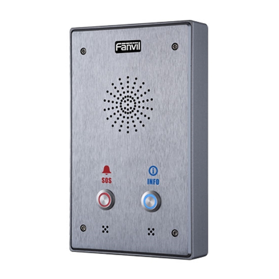
4 Overview i12 is a SIP voice intercom specially developed for the needs of industry users. The media stream transmission adopts the standard IP/RTP/RTSP protocol. It has inherited the advantages of good stability and carrier-grade sound quality of the azimuth phone. The product is a fully digital network-type intercom device. -
Page 9: Install Guide
POE switch through a network cable to play the role of power supply and data transmission. By connecting to the POE switch of the UPS system, the i12 can continue to work even if the power is cut off, just like a traditional PSTN phone powered by a telephone line. -
Page 10: Installation
5.2 Installation Before you start using the device, please install the following: 5.2.1 Interface description Expansion board interface Motherboard interface ... -
Page 11: A) Port Instructions
Port description Port Description Feature Picture Input Range:+9~+16V DC DC Power Input port (Notice: Plus-n-Minus connection of the Power) WAN port 10M/100M Adaptive Ethernet port, connected to the network 10M/100M Adaptive Ethernet port, connected to the computer LAN Port (which can be configured to routing mode, or to bridge mode) External Active One is the audio signal line, one is the GND line(Please connect to... - Page 12 Audio Recording output port Two short circuit output port NO: Under the idle state is disconnected (normally open). COM: Contactor of the Relay (middle). NC: Under the idle state is connected (normally close). Two short circuit input port ...
-
Page 13: Device Connection Confirmation
5.2.2 Device connection confirmation Check whether the power cord and network cable of the device are connected, and whether they normal after seconds after power-on. (Check network indicator status) Figure 1 - Connection Diagram 5.3 Appendix Table 5.3.1 Common command mode Table 1 - Common command mode Action Description... -
Page 14: Function Key Led State
5.3.2 Function key LED state Table 2 - Function key LED state Type State Line/Network Quick flashing Registration failed/ network abnormal Normally on Successfully registered Slow flashing In call... -
Page 15: User Getting Started
6 User Getting Started 6.1 Quick setting Before proceeding with this step, please confirm that your Internet broadband connection can work normally and complete the connection of the network hardware. The default network mode of this product when it leaves the factory is fixed IP address mode, and the default is 192.168.1.128. Long press the speed dial button for 10 seconds , wait for the horn to beep quickly, and then press ... -
Page 16: Sip Configurations
6.3 SIP Configurations At least one SIP line should be configured properly to enable the telephony service. The line configuration is like a virtualized SIM card. Just like a SIM card on a mobile phone, it stores the service provider and the account information used for registration and authentication. When the device is applied with the configuration, it will register the device to the service provider with the server’s address and user’s authentication as stored in the configurations. -
Page 17: Basic Function
7 Basic Function 7.1 Making Calls After setting the shortcut key as Hot key and setting the number, press the shortcut key to immediately call out the set number, the settings are as follows: Figure 5 - Hot Key Setting See detailed configuration instructions 9.26 Function Key 7.2 Answering Calls... -
Page 18: Auto-Answering
turn on the speed dial button to hang up the call. See detailed configuration instructions 9.26 Function Key. 7.4 Auto-Answering The user can turn off the auto-answer function (enabled by default) on the device webpage, and the ring tone will be heard after the shutdown, and the auto-answer will not time out. Web interface: enter [Intercom Setting] >>... -
Page 19: Call Waiting
Figure 8 - Set DND Option Turn on/off the DND of a specific line of the device, as follows: enter [Line] >> [SIP], choose a Line and enter [Line] >> [Advanced settings], Enable DND. Figure 9 - Enable do not disturb on a certain line 7.6 Call Waiting Enable call waiting: new calls can be accepted during a call. - Page 20 Figure 10 - Web page setting call waiting...
-
Page 21: Advance Function
8 Advance Function 8.1 Intercom When there is an intercom call, the device can answer it automatically. Figure 11 - WEB Intercom Table 3 - Intercom Parameters Description When the intercom system is enabled, the device will accept the Enable intercom SIP header Call-Info of the incoming call request Instruction to answer the phone automatically Automatically answer the call in intercom mode during the call, if... - Page 22 Figure 12 - MCAST Table 4 - MCAST Parameters Description Enable Auto Mcast Send the multicast configuration information by Sip Notify signaling, and the device will configure the information to the system for multicast listening or cancel the multicast listening in the system after receiving the information Auto Mcast Timeout When a multicast call does not end normally, but for some reason...
-
Page 23: Hotspot
8.3 Hotspot SIP hotspot is a simple utility. Its configuration is simple, can realize the function of group vibration, can expand the number of SIP account. Take one device A as the SIP hotspot and the other devices (B, C) as the SIP hotspot client. When someone calls device A, devices A, B, and C will ring, and if any of them answer, the other devices will stop ringing and not be able to answer at the same time. - Page 24 Figure 13 - SIP Hotspot The device is the hotspot server, and the default extension is 0.The device ACTS as a client, and the extension number is increased from 1 (the extension number can be viewed through the [SIP hotspot] page of the webpage).
-
Page 25: Web Configurations
9 Web Configurations 9.1 Web Page Authentication Users can log into the device's web page to manage user device information and operate the device. Users must provide the correct user name and password to log in. If the password is entered incorrectly three times, it will be locked and can be entered again after 5 minutes. -
Page 26: System >> Account
9.3 System >> Account Figure 14 - WEB Account On this page the user can change the password for the login page. Users with administrator rights can also add or delete users, manage users, and set permissions and passwords for new users 9.4 System >>... -
Page 27: System >> Upgrade
Import the configuration file of Settings. The device will restart automatically after successful import, and the configuration will take effect after restart Reset Phone The phone data will be cleared, including configuration and database tables. 9.5 System >> Upgrade Figure 16 - Upgrade Upgrade the software version of the device, and upgrade to the new version through the webpage. - Page 28 Fanvil devices support SIP PnP, DHCP options, Static provision, TR069. If all of the 4 methods are enabled, the priority from high to low as below: PNP>DHCP>TR069> Static Provisioning Transferring protocol: FTP、 TFTP、 HTTP、 HTTPS Details refer to Fanvil Auto Provision http://www.fanvil.com/Uploads/Temp/download/20180920/5ba38170d79fb.pdf...
- Page 29 Custom Option Custom option number. Must be from 128 to 254. Value Enable DHCP Set the SIP server address through DHCP option 120. Option 120 SIP Plug and Play (PnP) Whether enable PnP or not. If PnP is enable, phone will send a SIP SUBSCRIBE message with broadcast method.
-
Page 30: System >> Fdms
9.7 System >> FDMS Figure 18 - FDMS Table 7 - FDMS FDMS information Settings Community Name Name of equipment installation community Building Number Name of equipment installation building Room Number Equipment installation room name 9.8 System >> Tools This page gives the user the tools to solve the problem. Figure 19 - Tools Syslog :... -
Page 31: Network >> Basic
Fanvil technical support. 9.9 Network >> Basic This page allows users to configure network connection types and parameters. Figure 20 - Network Basic Setting Table 8 - Network Basic Setting Field Name Explanation Network Status The current IP address of the equipment... - Page 32 Account and Password must be input manually. These are PPPoE provided by your ISP. If Static IP is chosen, the screen below will appear. Enter values provided by the ISP. DNS Server Select the Configured mode of the DNS Server. Configured by Primary DNS Enter the server address of the Primary DNS.
-
Page 33: Network >> Advanced
9.10 Network >> Advanced Figure 21 - Basic network settings Advanced network settings are usually configured by IT administrators to improve the quality of equipment services Table 9 - Basic network parameters Parameters Description LLDP setting Report Enable LLDP Interval LLDP requests interval time Learning apply the learned VLAN ID to the phone configuration... -
Page 34: Network >> Vpn
9.11 Network >> VPN Figure 22 - VPN Virtual Private Network (VPN) is a technology to allow device to create a tunneling connection to a server and becomes part of the server’s network. The network transmission of the device may be routed through the VPN server. -
Page 35: Network >> Web Filter
Once the VPN is configured, the device will try to connect with the VPN automatically when the device boots up every time until user disable it. Sometimes, if the VPN connection does not establish immediately, user may try to reboot the device and check if VPN connection established after reboot. OpenVPN ... -
Page 36: Line >> Sip
Enable web page filtering: configure enable/disable web page access filtering; Click the "apply" button to take effect. Note: if the device you are accessing is in the same network segment as the phone, please do not configure the filter segment of the web page to be outside your own network segment, otherwise you will not be able to log in the web page. - Page 37 SIP Proxy Server Enter the SIP proxy server port, default is 5060 Port Outbound proxy Enter the IP or FQDN address of outbound proxy server provided by address the service provider Outbound proxy port Enter the outbound proxy port, default is 5060 Realm Enter the SIP domain if requested by the service provider Codecs Settings...
- Page 38 inactive After closing the grab packet, you can see that the DSP is sendonly and the hold is sendrecv Use Quote in Whether to add quote in display name Display Name Specific Server Type Set the line to collaborate with specific server type Registration Set the SIP expiration interval Expiration...
-
Page 39: Line >> Basic Settings
Enable Rport Set the line to add rport in SIP headers Enable PRACK Set the line to support PRACK SIP message Set the line to use DNS SRV which will resolve the FQDN in proxy Enable DNS SRV server into a service list Auto Change Port Enable/Disable Auto Change Port Keep Authentication... -
Page 40: Line >> Sip Hotspot
Figure 25 - Line Basic Setting Table 11 - Line Basic Setting Field Name Explanation SIP Settings Local SIP Port Set the local SIP port used to send/receive SIP messages. Registration Failure Set the retry interval of SIP REGISTRATION when registration Retry Interval failed. -
Page 41: Line >> Blacklist
Figure 26 - SIP Hotspot 9.16 Line >> Blacklist The function of restricting incoming calls is added to the webpage, and incoming calls can be restricted by setting a number or prefix. The rules are as follows: Add x, the type is number, then x cannot call. Add x and type as prefix, then the number starting with x cannot be called. - Page 42 Figure 28 - Function setting Table 12 - Common device function settings on the web Function setting Field Name Description General settings Limit call duration After enabling, hang up the call after timeout Call time Hang up after timeout DND (Do Not DND might be disabled phone for all SIP lines, or line for SIP individually.
-
Page 43: Intercom Settings >> Voice Settings
Configure the language of the voice prompt Descriptive information displayed on the IP scanning tool software or FDMS. Description The default is "i12" Configure the automatic hang-up time, if it is in hands-free mode, the device Auto hang up will automatically return to standby after the auto handdown time is... - Page 44 DTMF Set the DTMF payload type, ranging from 96 to 127, and the default is 101. payload type Preset Configure the default ringtone ringtone type G.729AB payload Configure the length of the G.729AB voice coding payload length Signal tone Configure the signal tone standard area standard G.722 Select time stamp for G.722 encoding, 160/20ms and 320/20ms can be...
-
Page 45: Intercom Settings >> Video Settings
9.19 Intercom Settings >> Video Settings Figure 30 - Video Setting Table 14 - Video Setting Connection Select external, click submit, restart the device mode Camera settings (external mode) Field Name Description Name Camera name Username External camera login name password External camera login password Camera type... -
Page 46: Intercom Settings >> Multicast
Sendrecv: to create a call, the SDP package in the invite package is Sendrecv RTSP Over TCP The RTSP goes over the TCP protocol H.264 Payload Set the h. 264 Payload type. The range is between 96 and 127. The default is Type Default Call Optional main stream and substream... -
Page 47: Intercom Settings >> Action Url
delete time reasons, the device can no longer receive the multicast rtp packet, through this configuration, the monitoring will be cancelled after the specified time SIP priority The priority defined in the current call, 1 is the highest priority, and 10 is the lowest. -
Page 48: Intercom Setting >> Time/Date
Note! The operation URL is used by the IPPBX system to submit device events. Please refer to the details Fanvil Action URL。 http://www.fanvil.com/Uploads/Temp/download/20190122/5c46debfbde37.pdf 9.22 Intercom Setting >> Time/Date Users can configure the device's time Settings on this page. Figure 32 - Time/Date... -
Page 49: Intercom Settings >> Certificate Management
Location Select the user's time zone specific area Select automatic DST according to the preset rules of DST, or DST Set Type the manually input rules Offset The DST offset time Month Start The DST start month Week Start The DST start week Weekday Start The DST start weekday Hour Start... -
Page 50: Security Settings
Figure 34 - Device certificate settings 9.25 Security Settings Figure 35 - Security Settings Table 17 - Security Settings Security Settings Explanation Field Name Input settings Explanation Field Name Input Detect Enable or disable Input Detect When choosing the low level trigger (closed trigger), detect the input port (low level) closed trigger. - Page 51 port (high level) disconnected trigger. Alert message Enable or disable the input port to send messages to the server sent to the server Send reset Enable or disable sending reset messages to the server message to server Output Settings Output port Enable or disable output response response When low level (NO: open) is selected, when the trigger condition is met, the...
-
Page 52: Function Key >> Function Key
IP:PORT, SIP number). When the input port is triggered, a short message will be sent to the Server Address server. The message format is as follows: Alarm Info: Description=i12;SIP User=;Mac=00:a8:34:68:23:d1;IP=172.18.2.243;port =Input1 (support variables and strings) 9.26... - Page 53 Figure 36 - Function keys Table 18 - Function keys Type Subtype Usage None No responding Redial User can redial the last number dialed Call Back Call the nearest missed number Release Delete password input, cancel dialing input and Function end call keys Identification key...
- Page 54 Fill Using Speed Dial mode together with , can called Speed Dial define whether this call is allowed to be party’ The SIP hung up by re-pressing the speed dial s SIP account key. Hot Key accou correspondi In Intercom mode, if the caller’s IP nt or ng lines phone supports Intercom feature, the...
- Page 55 Keep pressing the set shortcut key to make a call, release it and hang up Advanced Settings Figure 39 - Advanced Settings Table 21 - Advanced Settings Advanced Settings Field Name Explanation Input port is multiplexed as function Enable or disable the input port to be multiplexed as speed dial button 2 key 2 Use Function Key to Enable or disable shortcuts to answer calls...
-
Page 56: Trouble Shooting
10 Trouble Shooting When the device is not working properly, users can try the following methods to restore the device to normal operation or collect relevant information to send a problem report to the Fanvil technical support mailbox. 10.1 Get Device System Information Users can obtain information through the [System] >>... - Page 57 If all configurations are correct, contact your service provider for support, or follow the instructions in "10.4 Network Data Capture" to obtain a registered network packet and send it to the Fanvil Support Email to help analyze the issue.
Need help?
Do you have a question about the i12 and is the answer not in the manual?
Questions and answers