Table of Contents
Advertisement
Quick Links
Download this manual
See also:
User Manual
Advertisement
Table of Contents

Related Manuals for Fanvil I20 T


Summary of Contents for Fanvil I20 T
- Page 1 Voice Access System I20 T Quick Installation Guide 1、Introduction...
-
Page 2: Interface Description
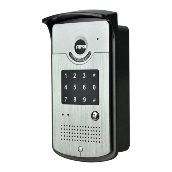
Package Contents I20-T Access Controller Amphenol Connector Software CD Quick Instanllation Guide 2、Voice Access Controller Components Description Housing Call/Answer Indicator Numeric Keypad(password and dialing) Red Light: Power Indicator Intercom call Button Green Light: Networking and registration status indicator Speaker Fixed screw 3、Interface Description... -
Page 3: Network, Power Switch, Electric Lock Connection
Network, Power Switch, Electric Lock Connection 12V DC Electric Lock Driver WAN(UTP Cable Connection) Output POE+ POE- 12V DC input Normally open, normally close port LAN(UTP Cable Connection) Electric Lock Connection Driver Option Outside Inside Driver Driver External Power Driving Internal Power Driving Jumper Jumper... - Page 4 to the internal driven mode and use the POE of the Voice Access System or 12V DC to control the the switch of the electric lock ; When the initial electric current of the lock is more than 500mA/12V, you need to access to the external driven mode(Use specialized DC power to control the electric lock ) 3.3 Wiring Relay connection description:...
-
Page 5: Step 1:Connect Network
Electric lock power Electric Jumper mode of connection supply mode lock Interna External Outside Driver √ √ √ √ Outside Driver 4、Setup of Voice Access System Step 1:Connect Network Plug one side of a cable to the WAN socket of I20, then the connection of hardware is finished. - Page 6 Step 2:Get Device IP Address How to get IP Address: Method 1. Use iDoorPhoneNetworkScanner tool 1) iDoorPhoneNetworkScanner tool; Install enclosed 2)Ensure the computer which installed iDoorPhoneNetworkScanner.exe is in the same network with I20 Voice Access Controller. 3)Run iDoorPhoneNetworkScanner.exe to search corresponding device’s IP address. Method 2: Press “#”key for 5 seconds, the controller will report it IP number by itself.
- Page 7 VOIP Account Setting: Set SIP server address, port, user name, password and number. Then start registration. Step 4:Set Speed Dial Key Setting Speed Dial to call SIP accounts, configuring DSS KEY1 corresponding Type: Hok key, Value: number, line: the registered SIP line (the number corresponded to), subtype: Speed Dial. Then submit...
- Page 8 Step 5: Parameters Setting Voice Access Configuration Function Initial Value Setting Item Open Time Time for open the door, if time is up, the door will be closed automatically. After time is up, the call will be ended 120s Holding Time automatically.
-
Page 9: Card Management
phone calls, input password only. Remote Phonebook Number Remote phone number When IP phone calls, it Access code for visitor. When remote needs to input phone calls, if the number is in access Authentication authentication code list, you can input access code to open code control voice access the door. - Page 10 (3)Administration Card List 7.2Issue User Card Issue User Card (method 1): 1) Choose “Card Issuing” in “Door Card”. 2) Press “Apply” to submit new User Card. 3) Put IC card on the Reader Sensing Area, and make sure the reader responded. 4)...
- Page 11 5)Press “Apply”. 6)You can check the issuing records in “Door Card Table” Issue the User Card (Method 2): 1) Put Issue Administration Card on the Reader Sensing Area, the controller is on the state of issuing. 2) Put IC card on the Reader Sensing Area, and make sure the reader responded. 3)...
-
Page 12: Add Remote Visit Data
5)Press “Apply” . Delete the user card (Method 2): 1) Put Issue Administration Card on the Reader Sensing Area, the controller is on the state of deleting. 2) Put IC card on the Reader Sensing Area, and make sure the reader responded. 3)...
Need help?
Do you have a question about the I20 T and is the answer not in the manual?
Questions and answers