
Related Manuals for CYP EL-7400V


Summary of Contents for CYP EL-7400V
- Page 1 EL-7400V HDMI/VGA/Display Port Presentation Switch & Scaler with HDMI & HDBaseT™ Outputs OPERATION MANUAL...
- Page 3 DISCLAIMERS The information in this manual has been carefully checked and is believed to be accurate. CYP (UK) Ltd assumes no responsibility for any infringements of patents or other rights of third parties which may result from its use. CYP (UK) Ltd assumes no responsibility for any inaccuracies that may be contained in this document.
-
Page 4: Safety Precautions
SAFETY PRECAUTIONS Please read all instructions before attempting to unpack, install or operate this equipment and before connecting the power supply. Please keep the following in mind as you unpack and install this equipment: • Always follow basic safety precautions to reduce the risk of fire, electrical shock and injury to persons. -
Page 5: Table Of Contents
CONTENTS 1. Introduction ...........6 2. Applications ...........6 3. Package Contents ........6 4. System Requirements ......7 5. Features ..........7 6. Operation Controls and Functions ..8 6.1 Front Panel ........... 8 6.2 Rear Panel ............. 9 6.3 Remote Control ........10 6.4 IR Cable Pinouts ........11 6.5 OSD Menu ..........12 6.6 WebGUI Control ........30 6.7 RS-232 Control ..........35... -
Page 6: Introduction
1. INTRODUCTION This scaler has DisplayPort, HDMI and PC (VGA) inputs which can be freely selected for output at a scaled resolution of the user’s choosing over the mirrored HDMI and HDBaseT outputs. This unit also includes separate analogue and digital audio outputs to provide additional playback flex- ibility. -
Page 7: System Requirements
4. SYSTEM REQUIREMENTS HDMI, DisplayPort or VGA source equipment such as media players, video game consoles, PCs, or set-top boxes. HDMI receiving equipment such as HDTVs, monitors or audio amplifiers. A compatible HDBaseT receiver with 48V PoH and Optical Audio Return support is strongly recommended. -
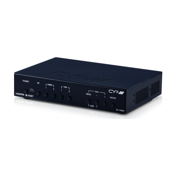
Page 8: Operation Controls And Functions
MENU – ENTER 720P EL-7400V POWER Button & LED: Press this button to power the unit on (Green LED) or place it into stand-by mode (Red LED). IR Window: Accepts IR signals from the included IR remote for control of this unit only. -
Page 9: Rear Panel
6.2 Rear Panel 4 5 6 INPUT OUTPUT OPT. RS-232 CAT5e/6/7 AUDIO SERVICE RS-232 DC 24V HDMI HDMI AUDIO COAX DP IN: Connect to DisplayPort source equipment such as a PC or laptop. Note: In some rare cases, digital DisplayPort audio can’t be supported. In those cases, please use analogue audio input 1. -
Page 10: Remote Control
IR IN: Connect to the provided IR Extender to extend the IR control range of remotely located devices. Ensure that the remote being used is within direct line-of-sight of the IR Extender. IR OUT: Connect to the provided IR Blaster to transmit IR signals to devices within direct line-of-sight of the IR Blaster. -
Page 11: Ir Cable Pinouts
6.4 IR Cable Pinouts IR Extender Infrared Power Ground IR Blaster Power Infrared... -
Page 12: Osd Menu
6.5 OSD Menu All functions of this unit can be controlled by using the OSD (On Screen Display) which is activated by pressing the Menu button on the front of the unit. Use the + (PLUS), − (MINUS), and ENTER buttons to navigate the OSD menu. - Page 13 VIDEO 2ND LEVEL 3RD LEVEL 4TH LEVEL Video Routing HDMI1 HDMI2 VGA1 VGA2 Output Native - CAT5e/6 Native - HDMI 640×480 60 800×600 60 1024×768 60 Output 1280×768 60 1360×768 60 1280×720 60 1280×800 60 1280×1024 60 1440×900 60 1400×1050 60 1680×1050 60 1600×1200 60 1920×1080 60...
- Page 14 VIDEO 2ND LEVEL 3RD LEVEL 4TH LEVEL Output (Cont.) 1280×720p 50 1920×1080p 50 1920×1080p 24 1920×1080p 25 1920×1080p 30 Aspect Overscan FULL Best Fit Pan Scan Letterbox Under 2 Under 1 Follow In DP HDCP Refer To Source REFER TO DISPLAY HDMI1 HDCP Refer To Source REFER TO DISPLAY...
- Page 15 VIDEO 2ND LEVEL 3RD LEVEL 4TH LEVEL BLACK No Signal Colour White Blue Green Blank Freeze Auto Setup Auto Sync Off 3 Min 5 Min 10 Min Auto Scan From DP From HDMI1 Auto Setup Auto Scan From HDMI2 From VGA1 From VGA2 Auto Switch...
- Page 16 VIDEO 2ND LEVEL 3RD LEVEL 4TH LEVEL VGA Setup Auto Setup [Current Status] H Position 0~250 V Position 0~250 Phase 0~255 0~250 (125) Clock Reset 1) Video Routing: Selects the input source to display. 2) Output: Selects the output resolution to use. Selecting Native- Cat.5e/6 or Native-HDMI will make the unit automatically select an output resolution based on the detected EDID of the connected display.
- Page 17 10) Auto Setup [submenu] Auto Sync Off: Sets the amount of time to continue outputting sync with the free run colour if there is no live source and no operations have been executed on the unit. Setting this to “OFF” forces the unit to always output sync.
- Page 18 PICTURE 2ND LEVEL 3RD LEVEL 0~1023 (512) Colour Gain R 0~1023 (512) Colour Gain G 0~1023 (512) Colour Gain B Colour Offset R 0~1023 (512) 0~1023 (512) Colour Offset G 0~1023 (512) Colour Offset B 0~60 (30) Brightness 0~60 (30) Contrast 0~60 (30) 0~60 (30)
- Page 19 6) Saturation: Provides control over the colour saturation level of the scaled output image. 7) Sharpness: Provides control over the amount of sharpness processing to apply to the scaled output image. 8) NR: Provides control over the aggressiveness of the digital noise reduction processing when applied to the scaled output image.
- Page 20 AUDIO 2ND LEVEL 3RD LEVEL FOLLOW VIDEO Audio Routing Audio 1 Audio 2 Audio 3 0~100 (80) HDMI Volume 0~100 (80) Coax Volume 0~100 (80) Analogue Volume HDMI Mute Coax Mute Analogue Mute Audio Delay 30ms 40ms 50ms 60ms 70ms 80ms 90ms 100ms...
- Page 21 AUDIO 2ND LEVEL 3RD LEVEL 150ms 160ms Audio Delay 170ms 180ms 190ms 200ms HDMI Audio Delay Coax Audio Delay Analogue Audio Delay Off Reset Audio 1) Audio Routing: Provides control over the analogue audio routing in the unit. Selecting “Follow Video” maps analogue audio 1 to all digital inputs (DisplayPort, HDMI 1 &...
- Page 22 7) Analogue Mute: Mutes or unmutes the analogue audio output. 8) Audio Delay: This control sets the amount of audio delay to use when audio delay has been enabled on any audio output. Selecting “Off” will disable audio delay for all output types. 9) HDMI Audio Delay: Enable or disable audio delay for the HDMI/ HDBaseT outputs.
- Page 23 2ND LEVEL 3RD LEVEL 0~60 (30) H Position 0~60 (30) V Position Timer 0~50 (50) Transparent Display Reset OSD 1) H Position: Set the horizontal position of the OSD menu. 2) V Position: Set the vertical position of the OSD menu. 3) Timer: Set the length of time to wait before automatically turning off the OSD menu if there is no user interaction.
- Page 24 4) Transparent: Set the transparency level of the OSD menu. A setting of 50 is completely opaque. 5) Display: Enable or disable the information display and set the length of time for the information display to be visible after a source or resolution change.
- Page 25 EDID 2ND LEVEL 3RD LEVEL DP EDID 1024×768 60 1280×800 60 1280×1024 60 1366×768 60 1440×900 60 1400×1050 60 1600×900 60 1600×1200 60 1680×1050 60 1920×1200 60 1280×720p 50 1280×720p 60 1920×1080p 50 1920×1080p 60 INT1 User1 User2 User3 Out-HDMI Out-CAT5e/6 HDMI1 EDID 1024×768 60...
- Page 26 EDID 2ND LEVEL 3RD LEVEL 1600×900 60 1600×1200 60 1680×1050 60 1920×1200 60 1280×720p 50 1280×720p 60 1920×1080p 50 1920×1080p 60 INT1 User1 User2 User3 Out-HDMI Out-CAT5e/6 HDMI2 EDID 1024×768 60 1280×800 60 1280×1024 60 1366×768 60 1440×900 60 1400×1050 60 1600×900 60 1600×1200 60 1680×1050 60...
- Page 27 EDID 2ND LEVEL 3RD LEVEL HDMI2 EDID 1920×1080p 50 1920×1080p 60 INT1 User1 User2 User3 Out-HDMI Out-CAT5e/6 VGA1 EDID 1024×768 60 1280×800 60 1280×1024 60 1366×768 60 1440×900 60 1400×1050 60 1600×900 60 1600×1200 60 1680×1050 60 1920×1200 60 1280×720p 50 1280×720p 60 1920×1080p 50 1920×1080p 60...
- Page 28 EDID 2ND LEVEL 3RD LEVEL 1280×800 60 1280×1024 60 VGA2 EDID 1366×768 60 1440×900 60 1400×1050 60 1600×900 60 1600×1200 60 1680×1050 60 1920×1200 60 1280×720p 50 1280×720p 60 1920×1080p 50 1920×1080p 60 INT2 User4 User5 DP EDID Status HDMI1 EDID Status HDMI2 EDID Status [Current EDID Selection] VGA1 EDID Status...
- Page 29 RESET 2ND LEVEL 3RD LEVEL Reset All Picture Reset All 1) Reset All Picture: Selecting this will reset all picture settings back to their factory defaults. 2) Reset All: Selecting this will reset all of the unit’s settings back to their factory defaults.
-
Page 30: Webgui Control
6.6 WebGUI Control Device Discovery Tool Please obtain the “Device Discovery” software from your authorised dealer and save it in a directory where you can easily find it. Connect the unit and your PC/Laptop to the same active network and ex- ecute the “Device Discovery”... - Page 31 WebGUI Overview After connecting to the WebGUI’s address in a web browser, the login screen will appear. Please enter the appropriate user name and password then click “LOGIN” to log in. Note: The default user name and password is “admin”. 6.6.1 Main Page 0 All primary functions of this unit are controllable via the built-in WebGUI.
- Page 32 STATUS This section provides information about the unit’s current input, output and HDCP status as well as the current Firmware Revision. VIDEO This section allows for control of input selection, output resolution & aspect ratio, HDCP behavior for the HDMI & DisplayPort inputs, the “no signal”...
- Page 33 AUDIO This section provides controls to set each individual audio output type’s volume levels, and delay settings. Each output type may also be muted independently. When the Audio Source is set to “Follow Video” the analogue audio inputs are mapped as follows: Audio 1 > Digital video (DisplayPort, HDMI 1 and HDMI 2), Audio 2 >...
- Page 34 “SAVE” button. Note: If the IP address is changed then the IP address required for WebGUI or Telnet access will also change accordingly. Consult the OSD to view the current IP settings if necessary. FWUPDATE This section allows for new firmware to be uploaded into the unit. To update the unit's firmware click the “Choose File”...
-
Page 35: Rs-232 Control
6.7 RS-232 Control UNIT TERMINAL SERIAL PORT SETTINGS Pinout Pinout Baud Rate 115200 Data Bits Parity Bit None Stop Bits Flow Control None 6.8 Telnet Control Before attempting to use Telnet control, please ensure that both the unit and the PC are connected to the same active networks. To Access the Command Line Interface (CLI) Click Start, type “cmd”... -
Page 36: Rs-232 And Telnet Commands
6.9 RS-232 and Telnet Commands COMMAND DESCRIPTION & PARAMETERS ? Show the full command list. HELP Show the full command list. GET N1 ? Show details about a specific command. N1 = {Base Command String} SET SYSTEM REBOOT Reboot the unit. - Page 37 COMMAND DESCRIPTION & PARAMETERS GET POWER Show the current power state. SET IP MODE N1 Set the IP address assignment mode. Available values for N1: [Static IP mode] [DHCP mode] GET IP MODE Show the current IP mode. SET IP ADDR N1 ...
- Page 38 COMMAND DESCRIPTION & PARAMETERS GET GATEWAY Show the current gateway. GET MAC ADDR Show the MAC address. SET INT EDID 1 TO INPUT N1 Assign Internal EDID 1 to input N1. Available values for N1: [DisplayPort] [HDMI 1] [HDMI 2] [All 3 digital inputs] SET INT EDID 2 TO INPUT N1 ...
- Page 39 COMMAND DESCRIPTION & PARAMETERS SET NATIVE EDID N1 TO INPUT N2 Assign Native EDID N1 to input N2. Available values for N1: [1024×768@60 EDID] [1280×800@60 EDID] [1280×1024@60 EDID] [1366×768@60 EDID] [1440×900@60 EDID] [1400×1050@60 EDID] [1600×900@60 EDID] [1600×1200@60 EDID] [1680×1050@60 EDID] [1920×1200@60 EDID] [1280×720P@ 50 EDID] [1280×720P@60 EDID]...
- Page 40 COMMAND DESCRIPTION & PARAMETERS SET USER EDID N1 TO INPUT N2 Assign User EDID N1 to input N2. Available values for N1: [User EDID 1] [User EDID 2] [User EDID 3] [User EDID 4] [User EDID 5] Available values for N2: [DisplayPort] [HDMI 1] [HDMI 2]...
- Page 41 COMMAND DESCRIPTION & PARAMETERS SET SINK EDID [N1] TO INPUT N2 Assign output N1’s EDID to input N2. Available values for N1: [HDMI output] [HDBaseT output] Available values for N2: [DisplayPort] [HDMI 1] [HDMI 2] [All digital inputs] GET SINK EDID [N1] DATA List output N1’s EDID data in ASCII HEX.
- Page 42 COMMAND DESCRIPTION & PARAMETERS SET INPUT N1 HDCP MODE N2 Set the HDCP handling method to use with input N1. Available values for N1: [DisplayPort] [HDMI 1] [HDMI 2] Available values for N2: [Off ] [Refer to source] [Refer to display] GET INPUT N1 HDCP MODE ...
- Page 43 COMMAND DESCRIPTION & PARAMETERS GET AUDIO ROUTE Show the current audio routing setting. SET AUDIO [N1] MUTE N2 Enable or disable audio muting for output type N1. Available values for N1: [HDMI] [Coaxial] [Analogue audio] Available values for N2: [Off ] [On] GET AUDIO [N1] MUTE ...
- Page 44 COMMAND DESCRIPTION & PARAMETERS SET AUDIO [N1] VOLUME N2 Set the audio volume for output type N1. Available values for N1: [HDMI] [Coaxial] [Analogue audio] N2 = 0 ~ 100 [Volume level] SET AUDIO [N1] VOLUME UP Increase the volume of audio type N1 by 1 unit. Available values for N1: [HDMI] [Coaxial]...
- Page 45 COMMAND DESCRIPTION & PARAMETERS SET AUDIO DELAY N1 Set the global audio delay setting. Available values for N1: [Off ] [30ms] [40ms] [50ms] [60ms] [70ms] [80ms] [90ms] [100ms] [110ms] [120ms] [130ms] [140ms] [150ms] [160ms] [170ms] [180ms] [190ms] [200ms] GET AUDIO DELAY Show the current global audio delay setting.
- Page 46 COMMAND DESCRIPTION & PARAMETERS SET AUDIO [N1] DELAY ENABLE N2 Enable or disable audio delay on output type N1. Available values for N1: [HDMI] [Coaxial] [Analogue audio] Available values for N2: [Off ] [On] GET AUDIO [N1] DELAY ENABLE Show the current audio delay setting for output type N1.
- Page 47 COMMAND DESCRIPTION & PARAMETERS GET SCALER [A] INPUT TIMING Show the video timing of the current input source. SET SCALER [A] OUTPUT TIMING N1 Set the scaled output resolution. Available values for N1: [Native - Cat.5e/6] [Native - HDMI] [640×480@60Hz] [800×600@60Hz] [1024×768@60Hz]...
- Page 48 COMMAND DESCRIPTION & PARAMETERS SET SCALER [A] ASPECT RATIO N1 Set the output aspect ratio. Available values for N1: [Overscan] [Full] [Best fit] [Pan & scan] [Letterbox] [Underscan 2] [Underscan 1] [Follow input] GET SCALER [A] ASPECT RATIO Show the current output aspect ratio.
- Page 49 COMMAND DESCRIPTION & PARAMETERS SET SCALER [A] NO SIGNAL Colour N1 Set the free run colour to use when there is no live source. Available values for N1: [Black] [White] [Blue] [Red] [Green] GET SCALER [A] NO SIGNAL Colour Show the currently selected free run colour.
- Page 50 COMMAND DESCRIPTION & PARAMETERS SET INPUT AUTO SCAN N1 Enable or disable the auto scan on signal loss function. Selecting a specific input will force the scan to begin with that input. Available values for N1: [Off ] [On] [DisplayPort] [HDMI 1] [HDMI 2]...
- Page 51 COMMAND DESCRIPTION & PARAMETERS GET INPUT N1 VGA AUTO Show the current status of the VGA auto setup function on input N1. Available values for N1: [VGA 1] [VGA 2] SET INPUT N1 VGA H POSITION N2 Set the horizontal position for input N1 (VGA inputs only). Available values for N1: [VGA 1] [VGA 2]...
- Page 52 COMMAND DESCRIPTION & PARAMETERS SET INPUT N1 VGA PHASE N2 Set the phase for input N1 (VGA inputs only). Available values for N1: [VGA 1] [VGA 2] N2 = 0 ~ 250 [Phase] GET INPUT N1 VGA PHASE Show the current phase of input N1.
- Page 53 COMMAND DESCRIPTION & PARAMETERS SET SCALER [A] OSD H POSITION N1 Set the horizontal position of the OSD. N1 = 0 ~ 60 [Horizontal position] GET SCALER [A] OSD H POSITION Show the current horizontal position of the OSD. SET SCALER [A] OSD V POSITION N1 ...
- Page 54 COMMAND DESCRIPTION & PARAMETERS GET SCALER [A] OSD TIMEOUT Show the current OSD menu timeout setting. SET SCALER [A] OSD TRANSPARENCY N1 Set the transparency level for the OSD menu. N1 = 0 ~ 50 [Transparency] GET SCALER [A] OSD TRANSPARENCY Show the current OSD menu transparency level.
- Page 55 COMMAND DESCRIPTION & PARAMETERS SET SCALER [A] B GAIN N1 Set the output’s blue gain level. N1 = 0 ~ 1023 [Blue gain] GET SCALER [A] B GAIN Show the current blue gain output level. SET SCALER [A] R OFFSET N1 Set the output’s red offset level.
- Page 56 COMMAND DESCRIPTION & PARAMETERS SET SCALER [A] CONTRAST N1 Set the output’s contrast level. N1 = 0 ~ 60 [Contrast] GET SCALER [A] CONTRAST Show the output’s current contrast level. SET SCALER [A] HUE N1 Set the output’s hue setting. N1 = 0 ~ 60 [Hue] GET SCALER [A] HUE ...
- Page 57 COMMAND DESCRIPTION & PARAMETERS SET SCALER [A] NR N1 Set the amount of noise reduction to apply to the output. Available values for N1: [Off ] [Low] [Middle] [High] [Auto] GET SCALER [A] NR Show the current noise reduction setting. Note 1: Commands will not be executed unless followed by a carriage return.
-
Page 58: Connection Diagram
7. CONNECTION DIAGRAM Smart TV RS-232 Controlled Device RS-232 1.5m 60° 60° Network Switch 1.5m 60° 60° Remote RS-232 Zone RS-232 Control HDBaseT Output System DP & Analogue Audio Inputs INPUT OUTPUT OPT. RS-232 CAT5e/6 AUDIO SERVICE RS-232 Power Supply HDMI HDMI AUDIO... -
Page 59: Specifications
8. SPECIFICATIONS 8.1 Technical Specifications HDMI Bandwidth 340MHz/10.2Gbps HDBaseT Bandwidth 340MHz/10.2Gbps Input Ports 1×DisplayPort 2×HDMI 2×VGA [HD-15] 3×3.5mm (Stereo Audio) Output Ports 1×HDMI 1×Cat.5e/6/7 1×TOSLINK (S/PDIF Audio) 1×RCA (S/PDIF Audio) 1×3.5mm (Stereo Audio) Pass-through Ports 1×IR Extender [3.5mm] 1×IR Blaster [3.5mm] 1×RS-232 [Terminal Block] Control Interfaces 1×RS-232 [9-pin D-sub]... - Page 60 Dimensions 215mm×42mm×144mm (W×H×D) [Case Only] 215mm×47mm×153mm (W×H×D) [All Inclusive] Weight 1,068g Chassis Material Metal Silkscreen Colour Black Operating Temperature 0 ˚C–40 ˚C/32 ˚F–104 ˚F Storage Temperature -20 ˚C–60 ˚C/-4 ˚F–140 ˚F Relative Humidity 20–90% RH (Non-condensing) Power Consumption...
-
Page 61: Video Specifications
8.2 Video Specifications Support Resolution/Timing (Hz) Input Output 640×480 60/72/75/85 60Hz 720×400 800×600 56/60/72/75/85 60Hz 1024×768 60/70/75/85 60Hz 1152×864 1280×720 1280×768 60/75/85 60Hz 1280×800 60/60 (RB) 60Hz 1280×960 ... -
Page 62: Audio Specifications
Support Resolution/Timing (Hz) Input Output (720) 1440×576i (720) 1440×480i 59.94/60 720×480p 59.94/60 60Hz 720×576p 1920×1080i 50/59.94/60 1920×1080p 23.97/29.97/59.94 1920×1080p 24/25/30/50/60 8.3 Audio Specifications Analogue Inputs Max Audio Level 2Vrms Input Impedance >10kΩ... -
Page 63: Acronyms
9. ACRONYMS ACRONYM COMPLETE TERM Analogue-to-Digital Converter Cat.5e Category 5 (enhanced) cable Cat.6 Category 6 cable Cat.7 Category 7 cable Command-Line Interface DisplayPort Digital Visual Interface EDID Extended Display Identification Data Graphical User Interface High-Definition HDCP High-bandwidth Digital Content Protection HDMI High-Definition Multimedia Interface HDTV... - Page 64 CYP (UK) Ltd., Unit 7, Shepperton Business Park, Govett Avenue, Shepperton, Middlesex, TW17 8BA Tel: +44 (0) 20 3137 9180 | Fax: +44 (0) 20 3137 6279 Email: sales@cypeurope.com www.cypeurope.com v1.01...
Need help?
Do you have a question about the EL-7400V and is the answer not in the manual?
Questions and answers