Table of Contents
Advertisement
Quick Links
Advertisement
Table of Contents

Related Manuals for CYP CLUX-2HPIP


Summary of Contents for CYP CLUX-2HPIP
- Page 1 CLUX-2HPIP 2×1 HDMI Multiviewer Operation Manual Operation Manual...
- Page 3 DISCLAIMERS The information in this manual has been carefully checked and is believed to be accurate. Cypress Technology assumes no responsibility for any infringements of patents or other rights of third parties which may result from its use. Cypress Technology assumes no responsibility for any inaccuracies that may be contained in this document.
-
Page 4: Revision History
SAFETY PRECAUTIONS Please read all instructions before attempting to unpack, install or operate this equipment and before connecting the power supply. Please keep the following in mind as you unpack and install this equipment: • Always follow basic safety precautions to reduce the risk of fire, electrical shock and injury to persons. -
Page 5: Table Of Contents
CONTENTS 1. Introduction ............1 2. Applications .............1 3. Package Contents ..........1 4. System Requirements ........2 5. Features ............2 6. Operation Controls and Functions ....3 6.1 Front Panel ..........3 6.2 Rear Panel ..........4 6.3 WebGUI Control ........5 6.4 RS-232 Control ......... 15 6.5 Telnet Control .......... -
Page 6: Introduction
1. INTRODUCTION This HDMI Multiviewer is capable of scaling up to 2 sources and displaying both simultaneously on a single HDMI output within their own windows. This is the ideal solution for monitoring multiple sources simultaneously for use in control rooms, or for flexible display presentations in conference rooms or classrooms. -
Page 7: System Requirements
4. SYSTEM REQUIREMENTS • HDMI source equipment such as media players, video game consoles or set-top boxes. • HDMI receiving equipment such as an HDTV, monitor, or audio amplifier. • Analog audio receiving equipment such as headphones, an audio amplifier or powered speakers. 5. -
Page 8: Operation Controls And Functions
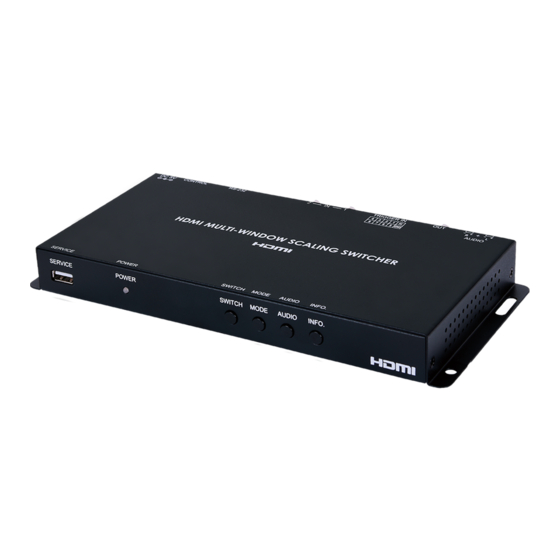
6. OPERATION CONTROLS AND FUNCTIONS 6.1 Front Panel SERVICE POWER SWITCH MODE AUDIO INFO. SERVICE: This port is reserved for firmware update use only. POWER LED: This LED will illuminate to indicate the unit is on and receiving power. SWITCH Button: Press to toggle between the two HDMI inputs and output the selected source full screen. -
Page 9: Rear Panel
6.2 Rear Panel AUDIO DC 5V TRIGGER IN RS-232 CONTROL AUDIO OUT: Connect to powered speakers or an amplifier for balanced stereo analog audio output. HDMI OUT: Connect to an HDMI TV, monitor or amplifier for digital video and audio output. TRIGGER IN: This 10 pin terminal block provides 8 trigger pins (plus 5V &... -
Page 10: Webgui Control
6.3 WebGUI Control • Device Discovery APP Please obtain the “Device Discovery” software from your authorized dealer and save it in a directory where you can easily find it. Connect the unit and your PC/Laptop to the same active network and execute the “Device Discovery”... - Page 11 • WebGUI Overview After connecting to the WebGUI’s address in a web browser, the login screen will appear. Please enter the appropriate user name and password then click “Submit” to log in. Note: The default user name and password is “admin”. On the left side of the browser you will see the following menu tabs where all primary functions of the unit are controllable via the built in WebGUI: Adjustment, Windows Setup, OSD/LOGO Settings,...
- Page 12 2) Information-Out: Provides the unit’s current output resolution as well as listing the current Window Mode. 3) Source: Provides controls for the A/V Mute function and Audio Source selection. ■ A/V Mute: When A/V Mute is enabled, all output will be disabled on the HDMI output.
- Page 13 Note: The output will briefly go black during the preset recall process. ■ Factory Reset: Click on the Factory Reset button to reset the unit to its factory default state. After the reset is complete, the unit will reboot automatically. Note: Network configuration details will not be reset. • Adjustment Tab This tab provides controls over the general display characteristics of each input channel as well as providing a way to set the unit’s output resolution.
- Page 14 6) Image Still: Freezes and unfreezes the video from the selected input channel. This function is off by default. 7) Flip: Enabling the Flip function will cause the video in the selected input channel to be mirrored horizontally. This function is off by default.
- Page 15 ■ Height: Sets the vertical size of the selected channel window in pixels. ■ H Position: Sets the horizontal position of the selected channel window in pixels. ■ V Position: Sets the vertical position of the selected channel window in pixels. Note: Changing channels before clicking “Save”...
- Page 16 ■ Edit: Clicking this button opens the OSD Information Edit window to change the formatting of the OSD. Text: Define a text string to display on the OSD. Font Color: Set the color of the OSD font. Background Color: Set the background color of the OSD’s text block.
- Page 17 1) Chromakey Setup: This section provides all controls relating to the chromakeying function of the unit. ■ Color Set: Select from a list of pre-set chromakey ranges (White, Yellow, Cyan, Green, Magenta, Red, Blue, Black) to perform simple, hassle-free keying or select “User” to enter in custom keying value ranges.
- Page 18 • Network Tab This tab provides access to control of the IP configuration and Login settings for the unit. 1) IP Configuration: The IP Address, Netmask and Gateway can be set manually, or DHCP can be enabled for automatic IP Configuration if your local network supports it.
- Page 19 • System Tab This tab provides firmware update functionality and, system configuration backup/restore functions. 1) System: This section contains all controls relating to firmware upgrades and system configuration export. ■ Firmware Upgrade: To update the unit's firmware, click the “Choose File” button to open the file selection window and then select the firmware update file (*.bin format) located on your local PC.
-
Page 20: Rs-232 Control
6.4 RS-232 Control UNIT TERMINAL SERIAL PORT SETTINGS Pinout Pinout Baud Rate 19200 Data Bits Parity Bit None Stop Bits Flow Control None 6.5 Telnet Control Before attempting to use Telnet control, please ensure that both the unit and the PC are connected to the same active networks. To Access the Command Line Interface (CLI) Click Start, type “cmd”... -
Page 21: Rs-232 And Telnet Commands
6.6 RS-232 and Telnet Commands COMMAND DESCRIPTION & PARAMETERS ? Show the full command list. HELP Show the full command list. GET FW VER Show the unit’s current firmware version. SET FACTORY DEFAULT Reset all configurations to the factory defaults. SAVE PRESET N1... - Page 22 COMMAND DESCRIPTION & PARAMETERS GET WINDOW LAYOUT MODE Show the currently selected windowing mode. SET OUT A WINDOW PRIORITY N1 Select which input window will have top display priority in the dual-windowing modes. N1 = 1 ~ 2 [Input port] GET OUT A WINDOW PRIORITY...
- Page 23 COMMAND DESCRIPTION & PARAMETERS [Sink] GET IN N1 EDID Show the EDID source currently used by input N1. N1 = 1 ~ 2 [Input port] SET OUT A TIMING N1 Set the scaled output resolution. Available values for N1: [Native] [480P60] [720P60] [1080P60]...
- Page 24 COMMAND DESCRIPTION & PARAMETERS SET OUT A AUDIO SOURCE N Select the HDMI audio source to send to the output. N1 = 1 ~ 2 [Input port] GET OUT A AUDIO SOURCE Show the currently selected HDMI audio source. SET OUT A MUTE N1 Enable or disable the audio/video output mute function.
- Page 25 COMMAND DESCRIPTION & PARAMETERS GET IN N1 BRIGHTNESS Show the current brightness value for input N1. N1 = 1 ~ 2 [Input port] SET IN N1 HUE N2 Set the hue shift for input N1. N1 = 1 ~ 2 [Input port] N2 = 0 ~ 100 [Hue]...
- Page 26 COMMAND DESCRIPTION & PARAMETERS SET IN N1 FORMAT N2 Force input N1 to use a specific color format. N1 = 1 ~ 2 [Input port] Available values for N2: [RGB] [YPbPr 4:2:2] [YPbPr 4:4:4] GET IN N1 FORMAT Show the currently set color space format used by input N1. N1 = 1 ~ 2 [Input port] SET IN N1 TEMPERATURE N2...
- Page 27 COMMAND DESCRIPTION & PARAMETERS SET CHROMAKEY ENABLE N1 Enable or disable Chromakey mode. Available values for N1: [Off] [On] GET CHROMAKEY ENABLE Show the current state of the Chromakey mode. SET CHROMAKEY COLOR N1 Select the RGB chromakey preset to use when Chromakey mode is enabled.
- Page 28 COMMAND DESCRIPTION & PARAMETERS SET CHROMAKEY GREEN RANGE N1 TO N2 Set the key-out range to use for the green component of the User defined key. N1= 00 ~ FF [Green min in hex] N2= 00 ~ FF [Green max in hex] SET CHROMAKEY BLUE RANGE N1 TO N2...
- Page 29 COMMAND DESCRIPTION & PARAMETERS SET IN N1 VPOSITION N2 Set the vertical position of the upper-left corner of input N1’s window in pixels. The maximum position value is the current vertical resolution minus 1. N1 = 1 ~ 2 [Input port] N2 = 0 ~ {Resolution-1} [Vertical position] Note: Only available in dual-windowing modes.
- Page 30 COMMAND DESCRIPTION & PARAMETERS GET IN N1 HEIGHT Show the current vertical size of input N1’s window in pixels. N1 = 1 ~ 2 [Input port] SET IN N1 UP-SIDE DOWN N2 Enable or disable the vertical flip function for input N1. N1 = 1 ~ 2 [Input port] Available values for N2:...
- Page 31 COMMAND DESCRIPTION & PARAMETERS GET IN N1 IMAGE STILL Show the current video freeze state for input N1. N1 = 1 ~ 2 [Input port] SET IN N1 BACKDROP COLOR N2 Set the free run color for input N1. N1 = 1 ~ 2 [Input port] Available values for N2: BLACK...
- Page 32 COMMAND DESCRIPTION & PARAMETERS SET OUT A OSD TEXT N1 Set the custom OSD text string. N1 = {Text string} [Custom text] GET OUT A OSD TEXT Show the current custom OSD text string. SET OUT A OSD FONT COLOR N1 Set the color of the OSD text.
- Page 33 COMMAND DESCRIPTION & PARAMETERS GET OUT A OSD BACKDROP COLOR Show the current OSD background color. SET OUT A OSD LOGO DISPLAY N1 Enable or disable the OSD graphical logo. Available values for N1: [Enabled] [Disabled] GET OUT A OSD LOGO DISPLAY Show the current state of the OSD graphical logo.
- Page 34 COMMAND DESCRIPTION & PARAMETERS SET WEBGUI TIMEOUT N1 Set the WebGUI inactivity timeout. N1 = 0 ~ 6000 [Timeout in minutes] GET WEBGUI TIMEOUT Show the current WebGUI inactivity timeout value. SET IP MODE N1 Set the IP address assignment mode. Available values for N1: [Static IP mode] [DHCP mode]...
- Page 35 COMMAND DESCRIPTION & PARAMETERS GET TELNET TIMEOUT Show the current Telnet inactivity timeout value. SET TELNET PORT N1 Set the network port to use for Telnet communication. N1 = 1 ~ 65535 [Telnet port] GET TELNET PORT Show the current Telnet port. Note: Commands will not be executed unless followed by a carriage return.
-
Page 36: Connection Diagram
7. CONNECTION DIAGRAM Camera Media Player RS-232 Control System HDMI RS-232 Inputs Trigger Inputs Display Display Source Source Screen Volume Power Supply Screen Volume Down Down Control AUDIO Keypad Network DC 5V TRIGGER IN RS-232 CONTROL Switch Analog Audio HDMI Output Output Powered... -
Page 37: Specifications
8. SPECIFICATIONS 8.1 Technical Specifications HDMI Bandwidth 225MHz/6.75Gbps Input Ports 2×HDMI Output Ports 1×HDMI 1×Stereo (Terminal Block) Control Interfaces 8×Trigger (Terminal Block) 1×RS-232 (9-pin D-sub) 1×IP Control (RJ-45) Baud Rate Up to 115200bps Power Supply 5V/2.6A DC (US/EU standards, CE/FCC/UL certified) ESD Protection Human Body Model: ±8kV (Air Discharge) -
Page 38: Video Specifications
8.2 Video Specifications Supported PC Resolution (Hz) HDMI Input HDMI Output 640×480@60 640×480@72 640×480@75 640×480@85 800×600@56 800×600@60 800×600@72 800×600@75 800×600@85 1024×768@60 ... -
Page 39: Audio Specifications
Supported TV Resolution (Hz) HDMI Input HDMI Output 720×480i@60 720×480p@60 720×576i@50 720×576p@50 1280×720p@50 1280×720p@60 1920×1080i@50 1920×1080i@60 1920×1080p@24 1920×1080p@25 1920×1080p@30 ... -
Page 40: Cable Specifications
8.4 Cable Specifications 1080p HDMI Cable Length 8-bit 12-bit Input Output 9. ACRONYMS ACRONYM COMPLETE TERM Command-Line Interface EDID Extended Display Identification Data Graphical User Interface High-Definition HDCP High-bandwidth Digital Content Protection HDMI High-Definition Multimedia Interface HDTV High-Definition Television Internet Protocol LPCM Linear Pulse-Code Modulation Personal Computer... - Page 44 CYPRESS TECHNOLOGY CO., LTD. www.cypress.com.tw...
Need help?
Do you have a question about the CLUX-2HPIP and is the answer not in the manual?
Questions and answers