Sign In
Upload
Manuals
Brands
Sick Manuals
Barcode Reader
CLV 421
User Manuals: Sick CLV 421 Barcode Scanner
Manuals and User Guides for Sick CLV 421 Barcode Scanner. We have
1
Sick CLV 421 Barcode Scanner manual available for free PDF download: Operating Instructions Manual
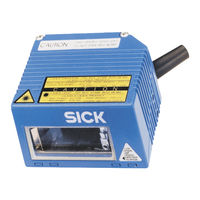
Sick CLV 421 Operating Instructions Manual (146 pages)
CLV42 Series
Brand:
Sick
| Category:
Barcode Reader
| Size: 3 MB
Table of Contents
SICK AG · Division Auto Ident · Germany · All Rights Reserved
2
Table of Contents
5
1 Notes on this Document
13
Function
13
Target Audience
13
Installation, Electrical Connection, Maintenance and Replacement
13
Startup, Operation and Configuration
13
Information Content
13
Symbols Used
14
2 Safety Information
15
Authorized Personnel
15
Installation and Maintenance
15
Electrical Connection and Replacement
15
Startup, Operation and Configuration
15
Intended Use
15
General Safety Instructions and Protection Measures
16
Fig. 2-1: Laser Warning Labels Found on the CLV
17
Quick Stop and Quick Restart
18
Switching off the CLV
18
Restarting the CLV
18
Environmental Information
18
Power Requirements
18
Disposal after Final Decommissioning
18
3 Product Description
19
Design
19
Scope of Delivery
19
Variants
19
Table 3-1: Variants of the CLV 42X
19
System Requirements
20
Product Features and Functions (Overview)
21
View of Line/Raster Scanner Devices
23
Fig. 3-1: Clv42X Line/Raster Scanner With/Without 105° Angle Attachment
23
Method of Operation
24
Fig. 3-2: Block Diagram: CLV Functions
24
Scan Procedure Variants
25
Indicators and Operating Elements
25
Operating Elements
25
Function of the LED Indicators
25
Fig. 3-3: LED Indicators
25
Table 3-2: Meaning of the LED Indicators
26
Function of the Beeper
27
Table 3-3: Beeper Function
27
4 Installation
29
Overview of Installation Sequence
29
Installation Preparations
29
Laying out Required Components to be Installed
29
Laying out Accessories
29
Laying out Other Required Materials
29
Replacing the Laser Warning Label
30
Selecting the Installation Location
30
Mounting Accessories
30
Fig. 4-1: Example Line Scanner: Replacing the Laser Warning Label
30
Fig. 4-2: Location of the Securing Threads on the CLV
31
Fig. 4-3: Installation Example: Mounting the CLV with Mounting Bracket
31
Distance between the CLV and the Bar Code
32
Fig. 4-4: Scanning Methods: Alignment with Bar Code and Conveyor Direction
32
Table 4-1: Permissible Reading Angles between the Scan Line and Bar Code
33
Fig. 4-6: Line Scanner: Reading Angles between the Scan Line and the Bar Code
33
Fig. 4-7: Preventing Surface Reflection: Angle between the Emitted Light and Bar Code (Tilted Away from the Vertical Axis)
33
Count Direction of the Code Position CP
34
Fig. 4-8: Count Direction of the Code Position CP Within the Scan Line
34
Installing and Adjusting the Device
35
Installing the CLV
35
Adjusting the CLV
35
Auxiliary Functions for Adjustment
36
Fig. 4-9: Line Scanner: Appearance of the Scan Line in the "Adjusting Mode" Operating Mode
36
Installing External Components
37
Installing the CDB 420 or CDM 420 Connection Module
37
Installing the External Reading Pulse Sensor
37
Fig. 4-10: Line Scanner: Installation Example for the External Reading Pulse Sensor
37
Installing the Polling Reflector
38
Table 4-2: Permissible Range Values for the Polling Reflectors
39
Fig. 4-11: Line Scanner: Installation Location of the Polling Reflector
39
Removing the Device
40
5 Electrical Connection
41
Overview of the Connection Sequence
41
Electrical Connections and Cables
41
Connections/Cables for the CDB 420 or CDM 420 Connection Module
41
Fig. 5-1: Block Diagram: Connection of the CLV to the CDB 420 or CDM 420 Connection Module
41
Connector Pin Assignment
42
Table 5-1: Pin Assignment of the 15-Pin D Sub HD Plug
42
Preparations for Electrical Connection
43
Requirements for the Host Interface
43
Power Supply
43
Table 5-2: Maximum Cable Lengths between the CLV and Host
43
Table 5-3: Power-Up Delay as a Function of the Device Number GN
43
Non-SICK Power Pack/Connections Without the SICK Connection Module
44
Making Electrical Connections
44
Overview of Connection Procedure
44
Auxiliaries
44
Table 5-4: Wiring Color Assignment of Cable No. 6 010 137 (Open End)
44
Connecting the Power Supply
45
Connecting the Host Interface
45
Fig. 5-2: Connections of the Host Interface
45
Connecting the CAN Interface
46
Table 5-5: Communication Parameters for the Host Interface (Default Setting)
46
Connecting the PC
47
Fig. 5-3: Connections of the Terminal Interface
47
Connecting the "Sensor 1" Switching Input
48
Connecting the "Sensor 2" Switching Input
48
Table 5-6: Characteristic Data of the "Sensor 1" Switching Input
48
Fig. 5-4: Connections of the "Sensor 1" Switching Input
48
Connecting the "Result 1" and "Result 2" Switching Outputs
49
Fig. 5-5: Connections of the "Sensor 2" Switching Input
49
Table 5-7: Characteristic Data of the "Result 1" and "Result 2" Switching Outputs
50
Fig. 5-6: Connections of the "Result 1" Switching Output
50
6 Operation
51
Overview of Procedure for Starting up the CLV
51
Default Settings
51
Default Settings: Line/Raster Scanner CLV 42X
52
Table 6-1: Extract: Default Parameter Settings of the Line/Raster Scanner CLV 42X
52
Quick Start
53
Starting up the Line/Raster Scanner with the Factory Default Settings
53
Table 6-2: Reading Distances for Module Width 0.35 MM (13.8 Mil), Default Settings
53
Fig. 6-1: Bar Code Pattern (Code 39; Module Width 0.35 MM (13.8 Mil); Print Ratio 2:1)
53
Configuration (Parameterizing)
54
Configuring CLV with the User Interface of CLV Setup
54
Function of Tabs in CLV Setup (Overview)
55
Parameterization Guide
57
Table 6-3: Guide: Parameterizing Reading Pulse Source
58
Table 6-4: Guide: Parameterizing Laser Timeout
58
Table 6-5: Guide: Settings to be Made for the Evaluation of Identical Bar Codes
59
Configuring the CLV with Autosetup
60
Fig. 6-2: CLV Setup: Autosetup Displayed in the Terminal Emulator
62
Operating Modes and Outputting the Reading Result
64
Reading Mode (Standard Operating Mode)
64
Fig. 6-3: CLV Setup: Output of the Reading Result of the Terminal Interface in Terminal Emulator
65
Chapter 6.2 Default Settings, Page
65
Fig. 6-4: Reading Result of the Terminal Interface: Structure for "Good Read
66
Fig. 6-5: Reading Result of the Terminal Interface: Structure for "No Read
66
Percentage Evaluation
67
Adjusting Mode
68
Fig. 6-6: CLV Setup: Display of the Percentage Evaluation in the Terminal Emulator
68
Show CP-Limits
69
Fig. 6-7: Appearance of Scan Line in the "Show CP-Limits" Mode
69
Displaying and Editing Operating Data
70
Reading Diagnosis
70
Fig. 6-8: CLV Setup: "Operating Data" Dialog Box
70
Monitor Host Interface
71
Table 6-6: "Monitor Host Interface" Function
71
Fig. 6-9: CLV Setup: Output of the Reading Result of the Host Interface in the Terminal Emulator at the Beginning (in this Case: O = Output)
72
Auxiliary Input
73
Self-Test
73
Fig. 6-10: CLV Setup: Displaying the Self-Test Result in the Terminal Emulator
73
Performing Device Functions of the CLV in the Dialog Box
74
Fig. 6-11: CLV Setup: Dialog Box for Autosetup Execution
74
CLV Messages
75
Displaying Messages
75
System Messages
75
Warnings
75
Error Messages
75
Table 6-7: Warnings
75
Switching off the CLV
76
7 Maintenance
77
Cleaning During Operation
77
Fig. 7-1: Cleaning the Reading Window
77
Maintenance
78
Disposal
78
Fig. 7-2: Cleaning the External Optical Sensor (Reading Pulse Generator)
78
8 Troubleshooting
79
Overview of Errors and Malfunctions Which Could Occur
79
Installation Errors
79
Electrical Connection Errors
79
Parameterization Errors
79
Malfunctions During Operation
79
Monitoring Errors and Malfunctions
79
Table 8-1: Error Message Output on the Terminal Interface
80
Error Status ST in Read Result of a Bar Code
82
Table 8-2: Meaning of the ST Error Status in the Reading Result
82
Troubleshooting
83
General Malfunction: CLV Not Ready
83
Table 8-3: Troubleshooting: Restoring Operation (Reading Mode)
83
Malfunctions in Reading Mode: Reading Pulse Errors
84
Table 8-4: Troubleshooting: Reading Pulse Errors in Reading Mode
84
Malfunctions in Reading Mode: Result Output Errors
85
Table 8-5: Troubleshooting: Result Output Errors in Reading Mode
85
Malfunctions in Reading Mode: Errors When Outputting the Result Status
87
Malfunctions: Configuration Errors (Parameterization)
87
Table 8-6: Troubleshooting: Errors in the Result Status Output in Reading Mode
87
Table 8-7: Troubleshooting: Configuration Errors (Parameterization)
87
SICK Support
88
9 Technical Data
89
Data Sheet CLV 420/421/422 Bar Code Scanners (Fixed Focus)
89
Table 9-1: Technical Specifications of the CLV 420/421/422 (Line/Raster Scanner)
89
CLV Dimensional Drawings
91
Fig. 9-1: Dimensions of the CLV 42X Line/Raster Scanner
91
10 Appendix
93
Overview
93
Specification Diagrams
93
Reading Conditions for All Diagrams
93
Table 10-1: Reading Conditions for Specification Diagrams
93
Reading Field Diagram for CLV 420 Line/Raster Scanner (Front Reading Window)
94
Fig. 10-1: CLV 420-0010/-1010: Reading Range (DOF) for Line/Raster Scanner
94
Reading Field Diagram for CLV 420 Line/Raster Scanner with 105° Angle Attachment (Lateral Reading Window)
95
Fig. 10-2: CLV 420-2010/3010: Reading Range (DOF) for Line/Raster Scanner with 105° Angle Attachment
95
Reading Field Diagram for CLV 421 Line/Raster Scanner (Front Reading Window)
96
Fig. 10-3: CLV 421-0010/1010: Reading Range (DOF) for Line/Raster Scanner
96
Reading Field Diagram for CLV 422 Line/Raster Scanner (Front Reading Window)
97
Fig. 10-4: CLV 422-0010/-1010: Reading Range (DOF) for Line/Raster Scanner
97
CLV 42X Characteristics Field of Scanning Frequency
98
System Messages
98
Table 10-2: CLV System Messages
98
Fig. 10-5: CLV 42X: Scanning Frequency Characteristic as a Function of the Reading Distance and Resolution
98
Installation and Operating Instructions for the PC-Based "CLV Setup" Program
99
Preparations for Installation
99
Installation
99
Starting "CLV Setup
102
Table 10-3: Default Settings of CLV Setup (Extract)
102
Fig. 10-6: CLV Setup: Results of the Autobaud Detect Function
103
CLV Setup Graphical User Interface
104
Fig. 10-7: User Interface of the "CLV Setup" Software
104
Functions
105
Hot Keys
105
Opening and Closing Tabs
106
Online Help - CLV Setup Help
106
Transferring Parameter Sets between CLV Setup and the CLV
107
10.4.10 Dealing with Unknown Parameters
107
10.4.11 Writing a Log File in Terminal Emulator
107
10.4.12 Starting CLV Setup with an INI File as an Argument
108
10.4.13 CLV Assistant
108
Configuring the CLV with Profile Bar Codes
109
Activating Autosetup with a Profile Bar Code
109
Profile Programming
111
Configuring the CLV with Command Strings
114
Table 10-4: Functions of Preprinted Profile Bar Codes on Card No. 8 008 085
114
Fig. 10-8: CLV Setup: Entering Commands in the Terminal Emulator
115
Calculating Parameter Values for Setting the CLV
116
Calculating the Number of Scans
116
Fig. 10-9: Line Scanner: Calculating the Number of Scans for Ladder-Type Bar Code Arrangements
116
Fig. 10-10: Line Scanner: Calculating the Number of Scans for Fence-Type Bar Code Arrangements
116
Tables
117
Calculating Code Length of a Bar Code
117
Table 10-5: Formulas for Calculating the Code Length of a Bar Code
117
Special Applications and Procedures
118
Triggering the Teach-In Match Code 1 Via the "Sensor 2" Switching Input
118
Auxiliary Input Via Terminal Interface
123
Fig. 10-12: Auxiliary Input Via the Terminal Interface of the CLV
124
Table 10-6: Communication Parameters on the Terminal/Pc for the Auxiliary Input
125
Fig. 10-13: CLV Setup: Auxiliary Input Via the Terminal Emulator
125
Connection to Profibus DP
126
Connection to Devicenet
126
Connection to Ethernet TCP/IP
126
Buildung up a CAN Scanner Network
126
Table 10-7: Communication Parameter Settings for the SICK Hand-Held Scanner from the IT 38Xx/46Xx/48Xx/58Xx Series
126
Replacing a CLV (Copying the Parameter Set)
127
10.10.1 Transferring the Parameter Set Using the Profile Bar Codes
127
10.10.2 Downloading the Parameter Set
128
10.11 Accessories
130
10.11.1 Installation Accessories
130
10.11.2 Connection Modules
130
10.11.3 Extensions for Connection Modules
130
Table 10-8: Accessories: Installation Accessories
130
Table 10-9: Accessories: Connection Modules
130
Table 10-10: Accessories: Extensions for Connection Modules
130
10.11.4 Cables and Plug-In Connections
131
10.11.5 Reading Pulse Generators
131
Table 10-11: Accessories: Cables and Plug-In Connections
131
Table 10-12: Accessories: Reading Pulse Generators (Polling Reflectors)
131
10.12 Dimensional Drawings of the Accessories
132
10.12.1 Mounting Bracket
132
10.13 Supplementary Documentation
133
CLV Connect (from Version 1.9)
133
Table 10-13: Supplementary Documentation
133
10.14 Glossary
134
10.15 EC Declaration of Conformity
140
Fig. 10-16: Copy of the Declaration of Conformity, Page 1 (Scaled Down)
140
10.16 Index
141
10.17 Bar Code Samples
145
Fig. 10-17: Scannable Bar Codes with Various Module Widths (Print Ratio 2:1)
145
Advertisement
Advertisement
Related Products
Sick CLV 420
Sick CLV 422
Sick CLV 490 Series
SICK CLV 480
SICK CLV 412
SICK CLV 45 Series
SICK CLV 450-0010
SICK CLV 450-6010
SICK CLV 451-6010
SICK CLV 490-1011
Sick Categories
Accessories
Security Sensors
Measuring Instruments
Scanner
Barcode Reader
More Sick Manuals
Login
Sign In
OR
Sign in with Facebook
Sign in with Google
Upload manual
Upload from disk
Upload from URL