Table of Contents
Advertisement
Advertisement
Table of Contents

Related Manuals for Elektron Analog Heat MKII


Summary of Contents for Elektron Analog Heat MKII
- Page 1 Analog Heat Stereo Analog Sound Processor User Manual...
-
Page 2: Fcc Compliance Statement
Elektron may also make improvements and/or changes in the products and programs described in this document at any time without notice. In no event shall Elektron be liable for any special, indirect, or consequential damages or any damages whatsoever resulting from loss of use, data, or profits, whether in an action of contract, negligence, or other action, arising out of or in connection with the use or performance of this information. - Page 3 • Do not exceed the limitations specified in the Electrical specifications. SAFETY INSTRUCTIONS FOR THE POWER ADAPTER ELEKTRON PSU-3b • The adapter is not safety grounded and may only be used indoors. • To ensure sufficient ventilation for the adapter, do not place it in tight spaces. To prevent the risk of elec- tric shock and fire because of overheating, ensure that curtains and other objects do not prevent adapter ventilation.
-
Page 5: Table Of Contents
TABLE OF CONTENTS TABLE OF CONTENTS 1. INTRODUCTION ..................7 1.1 CONVENTIONS IN THIS MANUAL . - Page 6 TABLE OF CONTENTS 6.6 SYSTEM ................. . . 19 6.6.1 USB CONFIG .
-
Page 7: Introduction
The right ear. Nobody wants the wrong one. Analog Heat User Manual. This manual is copyright © 2018 Elektron Music Machines MAV AB. All reproduction without written authorization is strictly prohibited. The information in this manual may change without notice. Elektron’s product names, logotypes, titles, words or phrases may be registered and protected by Swedish and international law. -
Page 8: Panel Layout And Connections
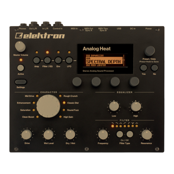
2. PANEL LAYOUT AND CONNECTIONS 2. PANEL LAYOUT AND CONNECTIONS 2.1 FRONT PANEL CONTROLS 1. MASTER VOLUME sets the master volume for the L/R and Headphones outputs. 2. [AMP] key accesses the AMP parameter page where you can set things such as drive amount and the volume of the preset. -
Page 9: Rear Panel Connections
2. PANEL LAYOUT AND CONNECTIONS 2.2 REAR PANEL CONNECTIONS 1. POWER, Switch for turning the unit on and off. 2. DC In, Input for power supply. Use the included PSU-3b power adapter, connected to a power outlet. 3. USB, For connecting the unit to a computer. For MIDI-control or Overbridge use. Connect to a computer host using the included A to B USB 2.0 connector cable. -
Page 10: First Steps With The Analog Heat
3. FIRST STEPS WITH THE ANALOG HEAT 3. FIRST STEPS WITH THE ANALOG HEAT 3.1 CONNECTING THE UNIT Make sure you place the Analog Heat on a stable support, such as a sturdy table with sufficient cable space. Before you start connecting the Analog Heat to other units, make sure all units are switched off. 1. -
Page 11: Setup Examples
Analog Heat in different configurations, please see "6.3.3 ANALOG IN/OUT" on page 16. 3.3.1 ANALOG HEAT AS AN EXTERNAL EFFECT In this example, the Analog Heat is used as an external effect to add color to the Elektron Octatrack before the signal reaches the mixer. -
Page 12: Signal Flow
4. SIGNAL FLOW 4. SIGNAL FLOW The illustrations below show the signal flows of the Analog Heat and illustrates how the different compo- nents interact with each other. 4.1 AUDIO SIGNAL FLOW This illustration shows the general flow of audio through the Analog Heat. The complete signal chain is in stereo. -
Page 13: Saving A Preset
5. THE USER INTERFACE 5.1.2 SAVING A PRESET 1. Press and hold PRESET/DATA for two seconds. The selected preset now starts to blink to illustrate that you are about to overwrite a preset position. 2. Turn PRESET/DATA to select the preset slot to where you want to save your sound, and then press [YES] 3. -
Page 14: Drive
5. THE USER INTERFACE 5.6 DRIVE Sets the gain level in the effect circuit. A higher setting increases the effect of the selected circuit type, typically resulting in more distortion. For more information, please see "4. SIGNAL FLOW" on page 12. 5.7 WET LEVEL Sets the level of the signal coming from the effect. -
Page 15: Overbridge
You need an Analog Heat, a USB cable, a computer running Overbridge, and a DAW. If you want to hook up multiple machines to a computer, you must use a USB hub. We suggest the Elektron Overhub, tailored for Overbridge use. It is Multi-TT hub and thereby also supports older Elektron machines. -
Page 16: Modulation
6. THE SETTINGS MENU • HIGH (Maximum input level 2,5 V, peak to peak) • MAX (Maximum input level 1,2 V, peak to peak) 6.2 MODULATION Here you can connect a number of modulation sources with their destinations and set the modulation depth. -
Page 17: Knob Mode
6. THE SETTINGS MENU • AUTO In Auto mode, Analog Heat automatically detects if the Overbridge plugin is running or not. With Overbridge running, the Analog In is not routed through the effect to the Analog Out. (Same as OFF setting.) If Overbridge is not running, the signal from analog is routed through the effect to the Analog Out. -
Page 18: Midi
6.5.2 PORT CONFIG • TURBO SPEED This setting allows Turbo mode negotiation between Elektron gear. Connecting the Analog Heat to other Turbo protocol compatible gear, like the Analog Rytm and the Octatrack, makes it possible to increase the average MIDI bandwidth by up to 10x. This increases the accuracy of MIDI clock signals as well as the timing of CC messages. -
Page 19: Channels
1. Download the OS syx file and the C6 software to your computer. 2. Select OS UPGRADE on the Analog Heat (If you wish to cancel the waiting state, press [NO].) 3. Open the C6 software. Click “Configure” and select Elektron Analog Heat for MIDI In as well as MIDI Out. -
Page 20: Drive
Test mode. Analog Heat is factory calibrated. It should not be re-calibrated unless specifically stated by Elektron Support or if prompted by the machine. 7. PARAMETER PAGES Here follows a description of all the parameters that are on the PARAMETER pages. You access the param- eter pages by pressing the [PARAMETER] keys. -
Page 21: Reso
7. PARAMETER PAGES 7.2.2 RESO Sets the amount of resonance at the cutoff point of the filter. (0.00–127.00) 7.2.3 ENV Sets the amount of how much the envelope and envelope follower affects the filter frequency. A negative value gives an inverted modulation. (-128.00–127.00) 7.2.4 LFO Sets the amount of how much the LFO affects the filter frequency. -
Page 22: Mode
7. PARAMETER PAGES 7.4.1 MODE Sets the mode of the envelope follower. Keep turning the knob to access the next mode. The higher the value under the selected mode, the more gain is added to the signal, which is useful for weak input signals. -
Page 23: Trig
7. PARAMETER PAGES 7.4.3 REL In Follow (FLW) mode, this is the fall time of the envelope follower, i.e. how quickly the follower falls when the amplitude of the audio falls. In generator mode (AD or AR), this is the decay- or release time of the generated envelope. -
Page 24: Depth1
7. PARAMETER PAGES 7.5.4 DEPTH1 Sets the amount of how much the envelope follower affects the modulation destination. A negative value gives an inverted modulation. (-128.00–+127.00) 7.6 LFO PAGE 1 Press [LFO] once to access this parameter page. 7.6.1 SPEED Sets the rate of the LFO in relation to the internal or external tempo. -
Page 25: Fade
8. TIPS & TRICKS 7.7.1 FADE FADE offers the possibility to fade in/out the LFO modulation. Positive values give a fade-out, negative values give a fade-in. A middle position (0) results in no fade in/out. The fade curve is restarted each time the LFO triggers. -
Page 26: Stereo Phaser Effect
8. TIPS & TRICKS 5. Press the [AMP] key to access AMP PAGE, and set VOL to 127. 6. Press the [ENV] key to access ENVELOPE PAGE 1, and set MODE to AD. Adjust the MODE (AD) param- eter until you clearly see the incoming signal in the TRIG meter. You should see the peaks and dips of the incoming signal, retaining as much as possible of dynamics of the signal. -
Page 27: Test Mode
Use the PRESET/DATA knob to scroll through the test log. A fully functional device should not report any errors. If it does report an error, please contact Elektron support or the retailer that you bought your Analog Heat from. -
Page 28: Technical Information
Sturdy steel casing Unit power consumption: 12 W typical Dimensions: W 215 x D 184 x H 63 mm (8.5” x 7.2” x Compatible Elektron power supply: PSU-3b 2.5”) (including power switch, jacks, knobs and feet) Weight: approximately 1.5 kg (3.3 lbs) 100 x 100 mm VESA mounting holes. -
Page 29: Appendix A: Midi
APPENDIX A: MIDI APPENDIX A: MIDI This appendix lists the CC and NRPN numbers for the Analog Heat. Parameter CC MSB CC LSB NRPN MSB NRPN LSB Specific values info Circuit Select 0=CB, 1=SA, 2=EN, 3=MD, 4=RC, 5=CD, 6=RF, 7=HG Drive Wet Level Dry/wet Mix... -
Page 30: Appendix B: Modulation Sources And Destinations
APPENDIX B: MODULATION SOURCES AND DESTINATIONS APPENDIX B: MODULATION SOURCES AND DESTINATIONS This appendix lists parameters that can be modulated by one or more of the following modulation sources; Envelope/Envelope Follower, LFO, and Expression pedal/CV. Modulation source Parameter EXP/CV Drive Wet Level Dry/Wet Mix Preset Volume... -
Page 31: Index
INDEX INDEX Phase 24 Speed 24 ACTIVE MODE 13 Waveform 24 AMPLIFIER 20 Drive 20 Dry/Wet 20 MIDI 18 Volume 20 CC, NRPN specification 29 Wet 20 Ports 18 AUDIO & ROUTING 16 Sync 18 MODULATION SOURCES/DESTINATIONS 30 CALIBRATION 19 CONNECTIONS 9 OS UPGRADE 19 CONTROL INPUTS 17...
Need help?
Do you have a question about the Analog Heat MKII and is the answer not in the manual?
Questions and answers