Table of Contents
Advertisement
Quick Links
OPTISENS TUR 2000
OPTISENS TUR 2000
OPTISENS TUR 2000
OPTISENS TUR 2000
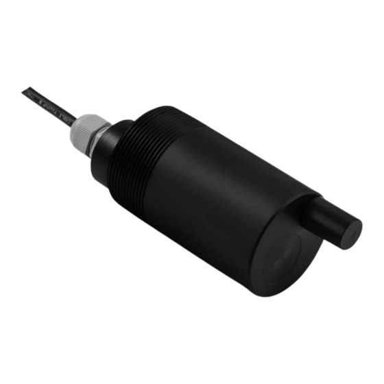
Sensor for turbidity measurement in water and
wastewater
The documentation is only complete when used in combination with the relevant
documentation for the signal converter.
© KROHNE 07/2017 - 4001970202 - MA OPTISENS TUR 2000 R01 en
Handbook
Handbook
Handbook
Handbook
Advertisement
Table of Contents

Related Manuals for KROHNE OPTISENS TUR 2000


Summary of Contents for KROHNE OPTISENS TUR 2000
- Page 1 Handbook Handbook Handbook Sensor for turbidity measurement in water and wastewater The documentation is only complete when used in combination with the relevant documentation for the signal converter. © KROHNE 07/2017 - 4001970202 - MA OPTISENS TUR 2000 R01 en...
- Page 2 All rights reserved. It is prohibited to reproduce this documentation, or any part thereof, without the prior written authorisation of KROHNE Messtechnik GmbH. Subject to change without notice. Copyright 2017 by KROHNE Messtechnik GmbH - Ludwig-Krohne-Str. 5 - 47058 Duisburg (Germany) www.krohne.com 07/2017 - 4001970202 - MA OPTISENS TUR 2000 R01 en...
-
Page 3: Table Of Contents
5.2.1 Calibration with a signal converter ..................26 5.2.2 Calibration log........................31 5.2.3 Calibration with PC ....................... 31 5.2.4 Communication protocol ...................... 32 5.2.5 Sensor mode options ......................32 5.3 Commands for operation via RS485................33 07/2017 - 4001970202 - MA OPTISENS TUR 2000 R01 en www.krohne.com... - Page 4 6.2.2 Form (for copying) to accompany a returned device............44 6.3 Disposal .......................... 44 7 Technical data 7.1 Measuring principle......................45 7.2 Technical data......................... 46 7.3 Dimensions and weight ....................47 www.krohne.com 07/2017 - 4001970202 - MA OPTISENS TUR 2000 R01 en...
-
Page 5: Safety Instructions
The manufacturer is not liable for any damage resulting from improper use or use for other than the intended purpose. The intended use of OPTISENS TUR 2000 sensors is the measurement of turbidity in water and wastewater applications. The sensor is suitable for connection to the MAC 100 signal converter. -
Page 6: Safety Instructions From The Manufacturer
The manufacturer reserves the right to alter the content of its documents, including this disclaimer in any way, at any time, for any reason, without prior notification, and will not be liable in any way for possible consequences of such changes. www.krohne.com 07/2017 - 4001970202 - MA OPTISENS TUR 2000 R01 en... -
Page 7: Product Liability And Warranty
This document is provided to help you establish operating conditions, which will permit safe and efficient use of this device. Special considerations and precautions are also described in the document, which appear in the form of icons as shown below. 07/2017 - 4001970202 - MA OPTISENS TUR 2000 R01 en www.krohne.com... -
Page 8: Warnings And Symbols Used
In general, devices from the manufacturer may only be installed, commissioned, operated and maintained by properly trained and authorized personnel. This document is provided to help you establish operating conditions, which will permit safe and efficient use of this device. www.krohne.com 07/2017 - 4001970202 - MA OPTISENS TUR 2000 R01 en... -
Page 9: Device Description
• SENSOFIT IMM 2000 - Immersion assembly Consumables / Spare parts available • Connector for cleaning hose • Turbidity standards for verification and calibration INFORMATION! For further information contact your local sales office. 07/2017 - 4001970202 - MA OPTISENS TUR 2000 R01 en www.krohne.com... -
Page 10: Device Description
2 Serial number as barcode 3 Order code 4 Articel number 5 Device name 6 Manufacturer 7 Electronic/electric device waste marking (WEEE dustbin symbol) 8 CE marking 9 Country of manufacture www.krohne.com 07/2017 - 4001970202 - MA OPTISENS TUR 2000 R01 en... -
Page 11: Installation
4 Rod holder 5 Mounting bracket INFORMATION! Install the sensor in a light angle to avoid wrong measurement results due to a dirty sensor or trapped air on the sensor. 07/2017 - 4001970202 - MA OPTISENS TUR 2000 R01 en www.krohne.com... -
Page 12: Storage And Transport
• Immersion assembly or other adequate housing If automatic flushing is installed, an optional solenoid valve is necessary as well. Examples of typical measuring points are listed in the following sections. www.krohne.com 07/2017 - 4001970202 - MA OPTISENS TUR 2000 R01 en... -
Page 13: Pre-Installation Requirements
Unpacking the sensor • Lay the sensor on a soft mat/tissue 1. • Keep the protection cap 2 in the original packaging as long as it is not required. 07/2017 - 4001970202 - MA OPTISENS TUR 2000 R01 en www.krohne.com... -
Page 14: Opening The Converter Housing
• Install a cap on the air line connector in order to avoid the cleaning drilling to be blocked for later use or water to flow through it into a closed assembly. www.krohne.com 07/2017 - 4001970202 - MA OPTISENS TUR 2000 R01 en... -
Page 15: Sensor Use With Cleaning Function
The pressurised air is to be provided and must be clean with a max of 3 bar. The typical cleaning time is 15 seconds and the typical cleaning frequency is 2 times/day, but this will differ from application to application. 07/2017 - 4001970202 - MA OPTISENS TUR 2000 R01 en www.krohne.com... -
Page 16: Mounting The Sensor Into An Assembly
For removing the sensor, repeat the steps above in reverse order. Calibrate the sensor before installing it into the assembly. For further information refer to Calibration on page 26 www.krohne.com 07/2017 - 4001970202 - MA OPTISENS TUR 2000 R01 en... -
Page 17: Electrical Connections
INFORMATION! Look at the device nameplate to ensure that the device is delivered according to your order. 07/2017 - 4001970202 - MA OPTISENS TUR 2000 R01 en www.krohne.com... -
Page 18: Connecting The Power Supply To The Signal Converter Mac 100
The manufacturer has designed all creepage distances and clearances according to VDE 0110 and IEC 664 for pollution degree 2. The power supply circuits fulfil the overvoltage category III and the output circuits fulfil the overvoltage category II. www.krohne.com 07/2017 - 4001970202 - MA OPTISENS TUR 2000 R01 en... - Page 19 (4 and 5). • Refasten the cover of the power supply terminal, close the converter housing and tighten all screws of the housing. 07/2017 - 4001970202 - MA OPTISENS TUR 2000 R01 en www.krohne.com...
-
Page 20: Connecting The Sensor Cable To The Signal Converter
Terminal block Pos.A Terminal block Pos.A White Green Yellow Grey None brown not connected Wire Wire Terminal S Terminal S Wire Wire Terminal S Terminal S Metal (non isolated cable) www.krohne.com 07/2017 - 4001970202 - MA OPTISENS TUR 2000 R01 en... - Page 21 • Push the wires 7 into terminal J 3, Q 4, Y5, V 6 and S 2. • To remove a wire, press down the white clip 8 on the corresponding terminal and pull the wire out. 07/2017 - 4001970202 - MA OPTISENS TUR 2000 R01 en www.krohne.com...
-
Page 22: Connecting The Sensor Directly To The Control System
The shield is not connected to the probe but it must be connected to the ground. Wire Function Shield not connected Yellow A (+) RS485 Grey B (-) RS485 Brown not connected Green + current loop White - current loop / COM RS485 www.krohne.com 07/2017 - 4001970202 - MA OPTISENS TUR 2000 R01 en... -
Page 23: Operation
A4 set clock A5 reset errors A6 analog > A6.1 measurement outputs A6.2 turbidity A6.3 range A6.4 time constant A17 offset A18 temperature offset A19 product cal. ↓↑ ↓↑ ↓↑ 07/2017 - 4001970202 - MA OPTISENS TUR 2000 R01 en www.krohne.com... - Page 24 B5.1 status log B5.2 calibration log B6 information B6.1 C number B6.2 process input A B6.4 SW.REV. MS B6.5 SW.REV. UIS B6.6 Electronic Revision ER ↓↑ ↓↑ ↓↑ ↓↑ www.krohne.com 07/2017 - 4001970202 - MA OPTISENS TUR 2000 R01 en...
- Page 25 C5.7 units ↓↑ ↓↑ ↓↑ ↓↑ D service: D service: D service: D service: This menu is password protected and contains functions to be used by service personnel only. 07/2017 - 4001970202 - MA OPTISENS TUR 2000 R01 en www.krohne.com...
-
Page 26: Calibration
Make sure there are no air bubble infront of the optics as they will be causing measurement signals due to reflection and light scattering effects and such might cause a wrong reading. www.krohne.com 07/2017 - 4001970202 - MA OPTISENS TUR 2000 R01 en... - Page 27 INFORMATION! Before proceding with product cal. product cal. product cal. product cal. make sure that the offset offset offset offset is set to 0.000 NTU 07/2017 - 4001970202 - MA OPTISENS TUR 2000 R01 en www.krohne.com...
- Page 28 • Tape three to four layers of new black electrical isolation tape across the detector window. • While taping you will notice that the measuring value decreases. • Make sure that the detector is absolutely sealed from light sources. www.krohne.com 07/2017 - 4001970202 - MA OPTISENS TUR 2000 R01 en...
- Page 29 • The sensor shall not stand vertical, but at a light angle to reduce any influences due to reflection. • Cover the setup with a cloth to shut out any interfering sun light. 07/2017 - 4001970202 - MA OPTISENS TUR 2000 R01 en www.krohne.com...
- Page 30 If the calibration was unsuccessful refer to Troubleshooting on page 40 • Step 8: switching back to measurement • Deactivate the function manual hold manual hold manual hold manual hold again. • Install the sensor in the measuring location. www.krohne.com 07/2017 - 4001970202 - MA OPTISENS TUR 2000 R01 en...
-
Page 31: Calibration Log
If during this 8 seconds interval digital activity is detected on the RS485 line it will switch to digital communication. Else it will remain in analog operation. The calibration and programming via PC gives additional possibilities concerning the signal calibration and is straight forward. 07/2017 - 4001970202 - MA OPTISENS TUR 2000 R01 en www.krohne.com... -
Page 32: Communication Protocol
After 2 seconds from switching the sensor on, the current will provide for 8 seconds a fixed current value depending of the selected scale: 8 mA for 4.000 NTU scale 12 mA for 40.00 NTU scale 20 mA for 400.0 NTU scale www.krohne.com 07/2017 - 4001970202 - MA OPTISENS TUR 2000 R01 en... -
Page 33: Commands For Operation Via Rs485
For example, if ID = 14, type 14H ^ or 00H ^ By sending the command 'H' the probe responds with a list of available commands with a brief description Figure 5-3: Help menu - List of all available commands 07/2017 - 4001970202 - MA OPTISENS TUR 2000 R01 en www.krohne.com... -
Page 34: Acquisition
The BCC is calculated as XOR of all bytes of the message (excluded <cr> and <lf>) and divided in 2 nibble. The 2 nibble are then transformed in ASCII codes. www.krohne.com 07/2017 - 4001970202 - MA OPTISENS TUR 2000 R01 en... -
Page 35: Digital Mode
In order to verify if the inserted value has been accepted, digit the command H INFORMATION! We suggest to use zero standards close to zero NTU value even if a small adjustment is possible for high reading values as well. 07/2017 - 4001970202 - MA OPTISENS TUR 2000 R01 en www.krohne.com... -
Page 36: Sensitivity Standard Setting
This command sets zero as default. Verify the result by means of the command ID + H and check the line “Zero calibration: not done” www.krohne.com 07/2017 - 4001970202 - MA OPTISENS TUR 2000 R01 en... -
Page 37: Sensitivity Calibration
Verify the lens surface and the air bubble absence first, eventually clean by using a soft tissue / cloth. The “Check signal cal.: not done” message will mean the parameter is turned to the default value through the Command ID + CR 07/2017 - 4001970202 - MA OPTISENS TUR 2000 R01 en www.krohne.com... -
Page 38: Check Signal Reset
The Command is for setting the alarm limit of the dirty or damaged lens surface. The Command sets the alarm limit of the dirty or damaged lens surface. www.krohne.com 07/2017 - 4001970202 - MA OPTISENS TUR 2000 R01 en... -
Page 39: Check Dry
ID + B + x command executed correctly Probe response: none command does not run properly The new baud rate will be available from the next switching on of the probe. 07/2017 - 4001970202 - MA OPTISENS TUR 2000 R01 en www.krohne.com... -
Page 40: Troubleshooting
400.0 NTU Zero adjustment ± 0.400 NTU on all scales 0 NTU Sensitivity adjusement 70...130% 100% Zero standard solution 0.000...400.0 NTU 0.020 NTU Sensitivity standard solution 0.000...400.0 NTU 400.0 NTU www.krohne.com 07/2017 - 4001970202 - MA OPTISENS TUR 2000 R01 en... -
Page 41: Serial Interface
1000 / 500 / 250 / 125 meter Baud rate 2400 / 4800 / 9600 bits 9600 bit Probes in network up to 32 Protocol ASCII Power supply Voltage 8...36 VDC Current 22 mA max. 07/2017 - 4001970202 - MA OPTISENS TUR 2000 R01 en www.krohne.com... -
Page 42: Service
The life time expectation of the sensor depends heavily on the application and if something that might scratch the measurement window or something chemical aggressive is in the water (medium) to be monitored. www.krohne.com 07/2017 - 4001970202 - MA OPTISENS TUR 2000 R01 en... -
Page 43: Returning The Device To The Manufacturer
• such dangerous substances, to enclose a certificate with the device confirming that it is safe to handle and stating the • product used. 07/2017 - 4001970202 - MA OPTISENS TUR 2000 R01 en www.krohne.com... -
Page 44: Form (For Copying) To Accompany A Returned Device
The user must dispose of the WEEE to a designated collection point for the recycling of WEEE or send them back to our local organisation or authorised representative. www.krohne.com 07/2017 - 4001970202 - MA OPTISENS TUR 2000 R01 en... -
Page 45: Technical Data
1 to 1. The advantage of the using NIR as light source as stated in the ISO 7027 is that this sensor is not affected by colour of the medium measured. 07/2017 - 4001970202 - MA OPTISENS TUR 2000 R01 en www.krohne.com... -
Page 46: Technical Data
Units displayed sensor NTU (= FNU) Installation conditions Ingress conditions IP68 Weight Body 420 g / 0.93 lb 10 meter cable 760 g / 1.41 lb Materials Sensor body www.krohne.com 07/2017 - 4001970202 - MA OPTISENS TUR 2000 R01 en... -
Page 47: Dimensions And Weight
EMC Directive 2004/108/EC (valid until 2016/04/19) or EMC Directive 2014/30/EU (valid from 2016/04/20) EN 61326-2-3:2013 EN 55011:2009+A1:2010 7.3 Dimensions and weight Dimensions [mm] Dimensions [inch] 0,71 3,94 5,51 0,98 07/2017 - 4001970202 - MA OPTISENS TUR 2000 R01 en www.krohne.com... - Page 48 • Process Analysis • Services Head Office KROHNE Messtechnik GmbH Ludwig-Krohne-Str. 5 47058 Duisburg (Germany) Tel.: +49 203 301 0 Fax: +49 203 301 10389 info@krohne.com The current list of all KROHNE contacts and addresses can be found at: www.krohne.com...
Need help?
Do you have a question about the OPTISENS TUR 2000 and is the answer not in the manual?
Questions and answers