Table of Contents
Advertisement
Quick Links
OPTISENS IND 1000
OPTISENS IND 1000
OPTISENS IND 1000
OPTISENS IND 1000
Inductive conductivity sensor
The documentation is only complete when used in combination with the relevant
documentation for the signal converter.
© KROHNE 12/2016 - 4001969202 - MA OPTISENS IND 1000 R02 en
Handbook
Handbook
Handbook
Handbook
Advertisement
Table of Contents

Related Manuals for KROHNE OPTISENS IND 1000


Summary of Contents for KROHNE OPTISENS IND 1000
- Page 1 OPTISENS IND 1000 OPTISENS IND 1000 Handbook Handbook Handbook Handbook Inductive conductivity sensor The documentation is only complete when used in combination with the relevant documentation for the signal converter. © KROHNE 12/2016 - 4001969202 - MA OPTISENS IND 1000 R02 en...
- Page 2 All rights reserved. It is prohibited to reproduce this documentation, or any part thereof, without the prior written authorisation of KROHNE Messtechnik GmbH. Subject to change without notice. Copyright 2016 by KROHNE Messtechnik GmbH - Ludwig-Krohne-Str. 5 - 47058 Duisburg (Germany) www.krohne.com 12/2016 - 4001969202 - MA OPTISENS IND 1000 R02 en...
-
Page 3: Table Of Contents
4.2.3 Menu C, setup ........................21 4.3 Calibration ........................23 4.3.1 Temperature compensation ....................23 4.3.2 Calibrating the temperature measurement................. 25 4.3.3 Calibrating measurement..................... 26 4.3.4 Calibration log........................30 4.4 Troubleshooting......................30 12/2016 - 4001969202 - MA OPTISENS IND 1000 R02 en www.krohne.com... - Page 4 5.4.2 Form (for copying) to accompany a returned device............32 5.5 Disposal .......................... 32 6 Technical data 6.1 Measuring principle......................33 6.1.1 Inductive conductivity measurement..................33 6.2 Technical data......................... 34 6.3 Dimensions ........................35 7 Notes www.krohne.com 12/2016 - 4001969202 - MA OPTISENS IND 1000 R02 en...
-
Page 5: Safety Instructions
The manufacturer is not liable for any damage resulting from improper use or use for other than the intended purpose. The intended use of OPTISENS IND 1000 conductivity sensor is the measurement of conductive liquids. The sensor is suitable for connection to the MAC 100 signal converter. -
Page 6: Disclaimer
This document is provided to help you establish operating conditions, which will permit safe and efficient use of this device. Special considerations and precautions are also described in the document, which appear in the form of icons as shown below. www.krohne.com 12/2016 - 4001969202 - MA OPTISENS IND 1000 R02 en... -
Page 7: Warnings And Symbols Used
In general, devices from the manufacturer may only be installed, commissioned, operated and maintained by properly trained and authorized personnel. This document is provided to help you establish operating conditions, which will permit safe and efficient use of this device. 12/2016 - 4001969202 - MA OPTISENS IND 1000 R02 en www.krohne.com... -
Page 8: Device Description
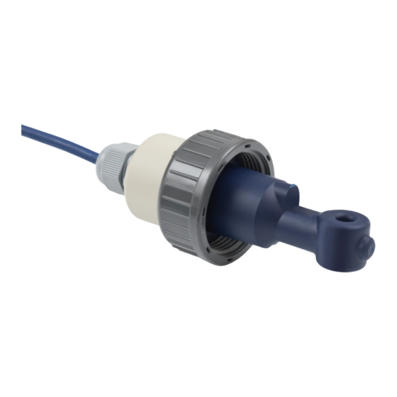
Check for the correct supply voltage printed on the nameplate. Figure 2-1: Standard scope of delivery 1 Ordered sensor with fixed cable 10 m / 33 ft 2 Documentation Optional accessories • SENSOFIT FLOW 1000 flow-through assembly (T-piece) www.krohne.com 12/2016 - 4001969202 - MA OPTISENS IND 1000 R02 en... -
Page 9: Device Description
Figure 2-2: Sensor rear view with guide slot Dimension [mm] Dimension [inch] 0.26 0.87 0.16 Figure 2-3: Sensor front view with exposed temperature sensor (standard sensor) Dimension [mm] Dimension [inch] 0.26 0.87 12/2016 - 4001969202 - MA OPTISENS IND 1000 R02 en www.krohne.com... - Page 10 0.26 0.87 The OPTISENS IND 1000 sensor features a compact and extremely rugged design as well as a wide measuring range. The meaurement coils are completely enclosed and there is no direct contact of the measurement coils to the medium. This feature makes it corrosion resistant and suitable for measurement mediums with a high dirt load.
-
Page 11: Nameplate
Figure 2-6: Example of a nameplate 1 Device name 2 Manufacturer 3 Matrix code of the serial number 4 Cell factor 5 Serial number 6 Articel number 7 Order code 12/2016 - 4001969202 - MA OPTISENS IND 1000 R02 en www.krohne.com... -
Page 12: Installation
(e.g. 25 mS/cm). Make sure the coils are minimum 20 mm away from any surface and fully immersed in the solution. 5. Install the sensor into its final measuring location. The required steps are explained in the following sections. www.krohne.com 12/2016 - 4001969202 - MA OPTISENS IND 1000 R02 en... -
Page 13: Pre-Installation Requirements
Free space around the sensor coil Approximate multiplier for cell factor correction DN32 ~8 mm ~1.09 (non conductive pipe) ~0.97 (conductive pipe). DN40 ~14 mm ~1.05 (non conductive pipe) ~0.98 (conductive pipe). DN50 ~21 mm ~1.00 12/2016 - 4001969202 - MA OPTISENS IND 1000 R02 en www.krohne.com... -
Page 14: Safety Instructions
"Pos.A" and "Pos.B" are populated. Figure 3-1: Terminal compartment overview 1 Sensor connection terminals 2 Terminal block S (protective earth) 3 Terminal block A : terminal for sensor www.krohne.com 12/2016 - 4001969202 - MA OPTISENS IND 1000 R02 en... -
Page 15: Calibrating The Sensor
3.6 Calibrating the sensor It is good practice to calibrate an inductive sensor before installation. For further information Calibrating measurement refer to on page 26. Then continue with the installation procedure. 12/2016 - 4001969202 - MA OPTISENS IND 1000 R02 en www.krohne.com... -
Page 16: Installing The Sensor
Always install the sensor in the designated flow through assembly or ensure that the pipe • diameter is large enough. The sensor must always have full contact with the measuring medium. • Figure 3-3: Installation requirements 1 Flow direction www.krohne.com 12/2016 - 4001969202 - MA OPTISENS IND 1000 R02 en... -
Page 17: Mounting To A Flow Through Assembly
The Sensor is also available as immersion version with 1000 or 2000 mm length. The sensor is already installed and sealed inside the assembly. The assembly is equipped with retaining clamps. 12/2016 - 4001969202 - MA OPTISENS IND 1000 R02 en www.krohne.com... -
Page 18: Examples Of A Typical Measuring Point
1 Bypass measurement 2 Outlet measurement 3 Shut-off valve 4 Flow-through assembly (T-piece) with sensor 5 Bypass pipe 6 Main pipe Figure 3-7: Installation with signal converter 1 Single channel version www.krohne.com 12/2016 - 4001969202 - MA OPTISENS IND 1000 R02 en... -
Page 19: Operation
B6.2 process input A C setup C setup C setup C setup C1 process input A C1.1 parameter C1.2 cell constant C1.14 time constant C1.15 temperature C1.23 cell calibration ↓↑ ↓↑ ↓↑ 12/2016 - 4001969202 - MA OPTISENS IND 1000 R02 en www.krohne.com... -
Page 20: Function Tables
"yes" (starts the simulation finally). • Choose the desired option with the help of ↑ or ↓ and press ^. If you chose "yes", the simulation starts. www.krohne.com 12/2016 - 4001969202 - MA OPTISENS IND 1000 R02 en... -
Page 21: Menu C, Setup
The configuration cannot be changed later. INFORMATION! Note that the appearance of some submenus depends on the hardware setting and the used sensor(s). 12/2016 - 4001969202 - MA OPTISENS IND 1000 R02 en www.krohne.com... - Page 22 • Press enter to proceed. Wait until concentration is measured. C1.23.5 cell constant Enter cell constant. Check slope, press enter, decide whether to store or to discard calibration parameter. www.krohne.com 12/2016 - 4001969202 - MA OPTISENS IND 1000 R02 en...
-
Page 23: Calibration
If you are in this mode and you want to choose the temperature compensation, you have to perform the following step: 12/2016 - 4001969202 - MA OPTISENS IND 1000 R02 en www.krohne.com... - Page 24 Press > > > > to enter the chosen menu. • Now you can set up the temperature compensation. Press to select off off or linear linear linear linear. Press ^ to confirm the entered value. www.krohne.com 12/2016 - 4001969202 - MA OPTISENS IND 1000 R02 en...
-
Page 25: Calibrating The Temperature Measurement
• If necessary, enter the temperature correction in Kelvin so that the signal converter shows the same temperature as the reference thermometer. Press ^ to confirm the entered value. The temperature sensor has been adjusted. 12/2016 - 4001969202 - MA OPTISENS IND 1000 R02 en www.krohne.com... -
Page 26: Calibrating Measurement
Meanwhile the status messages show "checks in progress". For more details about how to select the manual hold function refer to the signal converter manual. www.krohne.com 12/2016 - 4001969202 - MA OPTISENS IND 1000 R02 en... - Page 27 After activating the manual hold function and the preparative measures, you can get access to the calibration procedure from the measuring mode via the main menu setup setup (step 3). setup setup 12/2016 - 4001969202 - MA OPTISENS IND 1000 R02 en www.krohne.com...
- Page 28 • Press > > > > to enter the chosen menu. • You can start the calibration procedure now as described in "Step 4". www.krohne.com 12/2016 - 4001969202 - MA OPTISENS IND 1000 R02 en...
- Page 29 Do not change the compensation method in the time between the measurement of the "stored value" and the input of the reference value. Otherwise this could result in a wrong calibration. 12/2016 - 4001969202 - MA OPTISENS IND 1000 R02 en www.krohne.com...
-
Page 30: Calibration Log
A/B. cell factor * 100 µS/cm. This is for the sensor in PP > 625 µS/cm. www.krohne.com 12/2016 - 4001969202 - MA OPTISENS IND 1000 R02 en... -
Page 31: Service
• such dangerous substances, to enclose a certificate with the device confirming that is safe to handle and stating the • product used. 12/2016 - 4001969202 - MA OPTISENS IND 1000 R02 en www.krohne.com... -
Page 32: Form (For Copying) To Accompany A Returned Device
The user must dispose of the WEEE to a designated collection point for the recycling of WEEE or send them back to our local organisation or authorised representative. www.krohne.com 12/2016 - 4001969202 - MA OPTISENS IND 1000 R02 en... -
Page 33: Technical Data
Figure 6-1: Inductive measurement 1 Flow direction 2 Sinusoidal AC voltage supply 3 Induced voltage measurement 4 Exposed temperature sensor Pt1000 5 Measuring medium 12/2016 - 4001969202 - MA OPTISENS IND 1000 R02 en www.krohne.com... -
Page 34: Technical Data
4 bar at +80°C / 58 psi at 176°F 0 bar at +100°C / 0 psi at 212°F Installation conditions Process connection Pipe installation with G1½ PVC or stainless steel union nut Immersion version www.krohne.com 12/2016 - 4001969202 - MA OPTISENS IND 1000 R02 en... -
Page 35: Dimensions
9.2 m / 30 ft. (1 meter immersion version) 8.2 / 26 ft. ( 2 meter immersion version) 6.3 Dimensions Figure 6-2: Sensor Dimensions [mm] Dimensions [inch] 4.65 2.64 44.5 1.75 36.5 1.44 12/2016 - 4001969202 - MA OPTISENS IND 1000 R02 en www.krohne.com... - Page 36 [mm / inch] øb [mm / inch] Material Max. Temp. 88 / 3.46 40 / 1.57 +60°C / +140°F 102 / 4.02 50 / 1.97 124 / 4.88 63 / 2.48 www.krohne.com 12/2016 - 4001969202 - MA OPTISENS IND 1000 R02 en...
- Page 37 OPTISENS IND 1000 Figure 6-4: Immersions assembly Dimensions [mm] Dimensions [inch] 0.83 120 +/- 10 4.72 +/- 0.4 1000 / 2000 39.37 / 78.74 44.5 1.75 1.57 1.57 0.87 12/2016 - 4001969202 - MA OPTISENS IND 1000 R02 en www.krohne.com...
-
Page 38: Notes
NOTES OPTISENS IND 1000 www.krohne.com 12/2016 - 4001969202 - MA OPTISENS IND 1000 R02 en... - Page 39 NOTES OPTISENS IND 1000 12/2016 - 4001969202 - MA OPTISENS IND 1000 R02 en www.krohne.com...
- Page 40 • Process Analysis • Services Head Office KROHNE Messtechnik GmbH Ludwig-Krohne-Str. 5 47058 Duisburg (Germany) Tel.: +49 203 301 0 Fax: +49 203 301 10389 info@krohne.com The current list of all KROHNE contacts and addresses can be found at: www.krohne.com...
Need help?
Do you have a question about the OPTISENS IND 1000 and is the answer not in the manual?
Questions and answers