Table of Contents
Advertisement
Quick Links
TIDALFLUX 2300 F
TIDALFLUX 2300 F
TIDALFLUX 2300 F
TIDALFLUX 2300 F
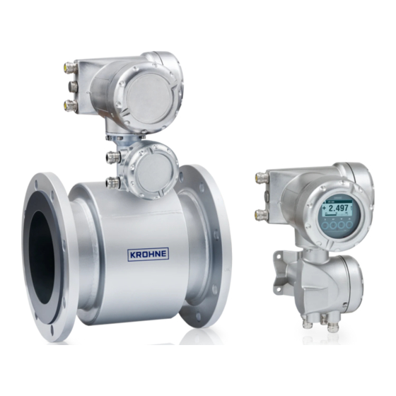
Electromagnetic flow sensor for partially filled pipes
The documentation is only complete when used in combination with the relevant
documentation for the signal converter.
© KROHNE 06/2013 - 4002489402 - QS TIDALFLUX 2300 R02 en
Quick Start
Quick Start
Quick Start
Quick Start
Advertisement
Table of Contents

Related Manuals for KROHNE TIDALFLUX 2300 F


Summary of Contents for KROHNE TIDALFLUX 2300 F
- Page 1 Quick Start Quick Start Quick Start Electromagnetic flow sensor for partially filled pipes The documentation is only complete when used in combination with the relevant documentation for the signal converter. © KROHNE 06/2013 - 4002489402 - QS TIDALFLUX 2300 R02 en...
-
Page 2: Table Of Contents
CONTENTS TIDALFLUX 2300 F 1 Safety instructions 2 Installation 2.1 Scope of delivery....................... 4 2.2 Device description ......................4 2.3 Nameplates ........................4 2.4 Storage ..........................4 2.5 Transport .......................... 5 2.6 Pre-installation requirements ..................5 2.7 General requirements ...................... 5 2.7.1 Vibration .......................... -
Page 3: Safety Instructions
SAFETY INSTRUCTIONS TIDALFLUX 2300 F Warnings and symbols used DANGER! This information refers to the immediate danger when working with electricity. DANGER! These warnings must be observed without fail. Even partial disregard of this warning can lead to serious health problems and even death. There is also the risk of seriously damaging the device or parts of the operator's plant. -
Page 4: Installation
INSTALLATION TIDALFLUX 2300 F 2.1 Scope of delivery Figure 2-1: Scope of delivery 1 Ordered flowmeter 2 Product documentation 3 Factory calibration report 4 CD-ROM with product documentation 5 Grounding rings (optionally) 6 Cable 2.2 Device description This flowmeter can measure the flow of conductive liquids, even in partially filled pipes. To be able to do this, a capacitive height measurement has been integrated into a regular electromagnetic flowmeter. -
Page 5: Storage
INSTALLATION TIDALFLUX 2300 F 2.4 Storage • Store the device in a dry and dust-free location. • Avoid lasting direct exposure to the sun. • Store the device in its original packaging. • Storage temperature: -50 ...+70°C / -58...+158°F 2.5 Transport Figure 2-3: Transport 2.6 Pre-installation requirements... -
Page 6: Vibration
INSTALLATION TIDALFLUX 2300 F 2.7.1 Vibration Vibration Figure 2-4: Avoid vibrations 2.7.2 Magnetic field Magnetic filed Figure 2-5: Avoid magnetic fields 2.8 Installation conditions 2.8.1 Inlet and outlet Figure 2-6: Recommended inlet and outlet sections, top view 1 ≥ 5 DN 2 ≥... -
Page 7: Control Valve
INSTALLATION TIDALFLUX 2300 F 2.8.2 Control valve Figure 2-7: Installation before control valve 2.8.3 Slope CAUTION! The accuracy is influenced by the slope. Stay within 1% to get the most accurate ± measurements! Figure 2-8: Recommended slope 2.8.4 Mounting advice for difficult situations If you can not meet the installation conditions install the flowmeter between two containers. -
Page 8: Open Discharge
INSTALLATION TIDALFLUX 2300 F 2.8.5 Open discharge Figure 2-10: Open discharge 1 ≥ 5 DN 2 Make sure that the water level stays below the pipe outlet. 2.8.6 Cleaning of flow sensor The flow sensor is highly resistant against dirt and the measurement will rarely be influenced by anything. -
Page 9: Mounting Position
INSTALLATION TIDALFLUX 2300 F 2.8.8 Mounting position CAUTION! Only install the flow sensor in the shown position to keep the electrodes under water. Limit the rotation to to maintain the accuracy. ± ° Figure 2-13: Mounting position 2.9 Mounting 2.9.1 Mounting grounding rings... -
Page 10: Torques And Pressures
INSTALLATION TIDALFLUX 2300 F 2.9.2 Torques and pressures Figure 2-15: Tightening of bolts Tightening of bolts • Always tighten the bolts uniformely and in diagonally opposite sequence. • Do not exceed the maximum torque value. • Step 1: Apply approx. 50% of max. torque given in table. -
Page 11: Temperatures
INSTALLATION TIDALFLUX 2300 F INFORMATION! Tighten the bolts uniformely in diagonally opposite sequence. Nominal size Pressure Bolts Max. torque [Nm] DN [mm] rating PN 10 8 x M 20 PN 10 12 x M 20 PN 10 12 x M 20... -
Page 12: Electrical Connections
ELECTRICAL CONNECTIONS TIDALFLUX 2300 F 3.1 Safety instructions DANGER! All work on the electrical connections may only be carried out with the power disconnected. Take note of the voltage data on the nameplate! DANGER! Observe the national regulations for electrical installations! WARNING! Observe without fail the local occupational health and safety regulations. -
Page 13: Connection Of Cables
ELECTRICAL CONNECTIONS TIDALFLUX 2300 F 3.3 Connection of cables The illustration shows the different connections and cable entries. View "p" shows (explicit) the bottom entries for signal and field current cables into the connection box on the signal converter. The diagrams for electrical connections and connection of mains supply, will be described on the next pages. -
Page 14: Cable Lengths
ELECTRICAL CONNECTIONS TIDALFLUX 2300 F 3.4 Cable lengths CAUTION! The maximum allowed distance between the flow sensor and the converter is determined by the shortest cable length. Interface cable Interface cable Interface cable Interface cable: maximum length is 600 m / 1968 ft. -
Page 15: Signal Cable B (Type Bts 300), Construction
ELECTRICAL CONNECTIONS TIDALFLUX 2300 F 3.5 Signal cable B (type BTS 300), construction • Signal cable B is a triple-shielded cable for signal transmission between the measuring sensor and signal converter. • Bending radius: ≥ 50 mm / 2" Figure 3-3: Construction of signal cable B 1 Stranded drain wire for the inner shield (10), 1.0 mm... -
Page 16: Preparing Signal Cable A, Connection To Measuring Sensor
ELECTRICAL CONNECTIONS TIDALFLUX 2300 F 3.7 Preparing signal cable A, connection to measuring sensor INFORMATION! Assembly materials and tools are not part of the delivery. Use the assembly materials and tools in compliance with the applicable occupational health and safety directives. -
Page 17: Preparing Signal Cable B, Connection To Measuring Sensor
ELECTRICAL CONNECTIONS TIDALFLUX 2300 F 3.8 Preparing signal cable B, connection to measuring sensor INFORMATION! Assembly materials and tools are not part of the delivery. Use the assembly materials and tools in compliance with the applicable occupational health and safety directives. -
Page 18: Preparing Field Current Cable C, Connection To Measuring Sensor
ELECTRICAL CONNECTIONS TIDALFLUX 2300 F 3.9 Preparing field current cable C, connection to measuring sensor INFORMATION! Assembly materials and tools are not part of the delivery. Use the assembly materials and tools in compliance with the applicable occupational health and safety directives. -
Page 19: Interface Cable
ELECTRICAL CONNECTIONS TIDALFLUX 2300 F 3.10 Interface cable The data interface cable is a shielded, 3 x 1.5 mm LIYCY cable. Preparing the interface cable Figure 3-8: Preparing the interface cable a = 100 mm / 4" b = 10 mm / 0.4"... - Page 20 ELECTRICAL CONNECTIONS TIDALFLUX 2300 F At flow converter side: Connecting shielding under clamp in connection box of converter Figure 3-9: Clamping of shields 1 Field current cable 2 Signal cable At flow sensor side: Connecting shielding via special cable gland...
-
Page 21: Grounding
ELECTRICAL CONNECTIONS TIDALFLUX 2300 F 3.11 Grounding DANGER! The device must be grounded in accordance with regulations in order to protect personnel against electric shocks. 3.11.1 Mounting grounding rings CAUTION! In order to get a reliable height measurement it is absolutely necessary... -
Page 22: Technical Data
TECHNICAL DATA TIDALFLUX 2300 F 4.1 Dimensions and weights The inner pipe diameter should match the inner diameter of the flowmeter. Since the inner diameter is not a standard DN size, choose the inner pipe diameter to be just a little bit bigger than the flowmeter diameter. - Page 23 TECHNICAL DATA TIDALFLUX 2300 F 150 lb flanges Nominal size Dimensions [inches] Approx. weight ASME Øc ØD ØD [lb] [psi] 13.78 22.93 11.46 5.75 13.5 7.44 15.75 24.80 13.03 6.54 16.0 9.09 19.69 26.76 7.52 19.0 11.06 27.56 30.22 16.85 21.0...
-
Page 24: Notes
• Measuring systems for the marine industry Head Office KROHNE Messtechnik GmbH Ludwig-Krohne-Str. 5 47058 Duisburg (Germany) Tel.:+49 (0)203 301 0 Fax:+49 (0)203 301 10389 info@krohne.de The current list of all KROHNE contacts and addresses can be found at: www.krohne.com...
Need help?
Do you have a question about the TIDALFLUX 2300 F and is the answer not in the manual?
Questions and answers