Table of Contents
Advertisement
Quick Links
Advertisement
Table of Contents

Related Manuals for CYP CDPS-U42HPIP


Summary of Contents for CYP CDPS-U42HPIP
- Page 1 CDPS-U42HPIP 4K UHD 4×2 HDMI Multiviewer Operation Manual Operation Manual...
-
Page 3: Copyright Notice
DISCLAIMERS The information in this manual has been carefully checked and is believed to be accurate. Cypress Technology assumes no responsibility for any infringements of patents or other rights of third parties which may result from its use. Cypress Technology assumes no responsibility for any inaccuracies that may be contained in this document. -
Page 4: Revision History
SAFETY PRECAUTIONS Please read all instructions before attempting to unpack, install or operate this equipment and before connecting the power supply. Please keep the following in mind as you unpack and install this equipment: • Always follow basic safety precautions to reduce the risk of fire, electrical shock and injury to persons. -
Page 5: Table Of Contents
CONTENTS 1. Introduction ............1 2. Applications .............1 3. Package Contents ..........1 4. System Requirements ........2 5. Features ............2 6. Operation Controls and Functions ....3 6.1 Front Panel ..........3 6.2 Rear Panel ..........4 6.3 Remote Control ......... 5 6.4 RS-232 Control ........... 6 6.5 Telnet Control .......... -
Page 6: Introduction
1. INTRODUCTION This 4 by 2 Multiviewer is a high performance HDMI switch with integrated scaling and multi-windowing technology. It is an ideal solution for monitoring or displaying multiple sources simultaneously for use in control rooms, conference rooms or classrooms. Video resolutions up to 4K@60Hz and LPCM audio up to 7.1 channels at 192kHz are supported on both input and output and this unit is fully compatible with the HDCP 1.x and 2.2 standards. -
Page 7: System Requirements
4. SYSTEM REQUIREMENTS • HDMI source equipment such as media players, video game consoles or set-top boxes. • HDMI receiving equipment such as HDTVs, monitors or audio amplifiers. 5. FEATURES • HDMI inputs and outputs with 18Gbps (600MHz) 4K UHD support •... -
Page 8: Operation Controls And Functions
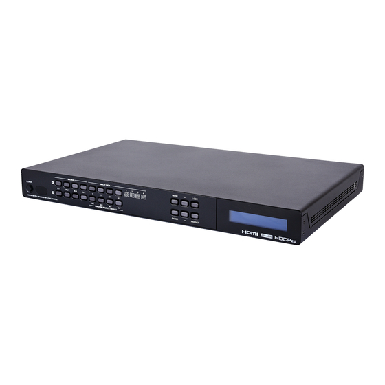
6. OPERATION CONTROLS AND FUNCTIONS 6.1 Front Panel MATRIX MULTI VIEW MENU LOCK POWER IN 1 IN 2 IN 3 IN 4 ENTER PRESET UHD 4X2 MATRIX / PIP SCALER WITH FREE WINDOWS WINDOW SOURCE SELECT 8 10 POWER: Press this button to power the unit on (green LED) or place it into stand-by mode (red LED). -
Page 9: Rear Panel
button again to release the lock function. The LCD will display a “Lock” message when the function is active. PRESET: Press this button to switch between the “Preset Load” and “Preset Save” modes. Pressing the button a 3rd time exits the Preset menu. -
Page 10: Remote Control
DC 12V: Plug the 12V DC power adapter into the unit and connect it to an AC wall outlet for power. 6.3 Remote Control INFO POWER POWER: Power on the machine or enter to standby mode. INFO: Display the current status/ information of the unit. -
Page 11: Rs-232 Control
EXIT: Press to exit out of the current LCD menu item. W1~W4: (Window Source Selection) Press these buttons to sequentially switch through the available inputs for each window (1~4) in Multiview output modes. SAVE: Pressing this button will save the currently displayed window layout. -
Page 12: Telnet Control
6.5 Telnet Control Before attempting to use Telnet control, please ensure that both the unit and the PC are connected to the same active networks. To Access the Command Line Interface (CLI) Click Start, type “cmd” in the search field, and Windows 7 press Enter. - Page 13 6.6.1 Basic Commands COMMAND DESCRIPTION VARIABLES GET MODEL TYPE Show the model type. SET FACTORY DEFAULT Reset the unit to its factory defaults. SET POWER N1 Available values for N1: Turn the unit on or off (standby). [Power on] STANDBY [Standby mode] GET POWER...
- Page 14 6.6.2 Ethernet Configuration COMMAND DESCRIPTION VARIABLES GET IP MODE Show the current IP mode. GET IPCONFIG Show the current IP configuration. SET IPADDR N1 N1 = X.X.X.X Set the unit’s static IP address. [X = 0~255, IP address] GET IPADDR Show the current IP address.
- Page 15 6.6.3 Video Settings COMMAND DESCRIPTION VARIABLES GET OUT N1 NAME Show the name of output N1. N1 = A~B [Output letter] SET OUT N1 ROUTE N2 N1 = A~B Set the routing source for output [Output letter] N1 and switch to matrix mode. N2 = 1~4 [Input number] GET OUT N1 ROUTE...
- Page 16 6.6.4 Basic Commands COMMAND DESCRIPTION VARIABLES Timing Codes: 0 = Native 1 = 640×480 2 = 480p@60 3 = 576p@50 4 = 800×600 5 = 848×480 6 = 1024×768 7 = 720p@50 8 = 720p@60 9 = 1280×768 10 = 1280×800 11 = 1280×960 12 = 1280×1024 13 = 1360×768...
- Page 17 6.6.4 Basic Commands COMMAND DESCRIPTION VARIABLES 34 = 4096×2160p@30 35 = 3840×2160p@50 36 = 3840×2160p@60 GET OUT A TIMING Show the current output resolution timing. SET WINDOW LAYOUT MODE N1 Available values for N1: Set the multiview window layout mode and switch to multiview [2×2 quad view] mode.
- Page 18 6.6.4 Basic Commands COMMAND DESCRIPTION VARIABLES SET WINDOW N1 ROUTE N2 N1 = 1~4 Set the input routing for the [Window number] windows in multiview mode. N2 = 1~4 [Input number] GET WINDOW N1 ROUTE N1 = 1~4 Show the input currently routed [Window number] to window N1.
- Page 19 6.6.4 Basic Commands COMMAND DESCRIPTION VARIABLES Note: The maximum value depends on, and cannot exceed, the current output resolution’s height. GET PIP VSIZE Show the current vertical PiP window size. SET PIP HPOSITION N1 N1 = 0~? Set the horizontal position of the [Horizontal position] top left corner of the PiP window (in pixels).
- Page 20 6.6.5 OSD Commands COMMAND DESCRIPTION VARIABLES Note: Enabling the info banner will automatically disable display of the graphic logo. GET OUT A OSD BANNER DISPLAY Show the current state of the OSD info banner display. SET OUT A OSD BANNER LOCATION N1 Available values for N1: Set the position of the OSD info banner.
- Page 21 6.6.5 OSD Commands COMMAND DESCRIPTION VARIABLES GET OUT A INFO LOGO HPOSITION Show the graphic logo’s current horizontal position. SET OUT A INFO LOGO VPOSITION N1 N1 = 0~? Set the vertical position of the top [Vertical position] left corner of the graphic logo (in pixels).
- Page 22 6.6.6 Audio COMMAND DESCRIPTION VARIABLES SET AUDIO OUT A VOLUME N1 Available values for N1: Set or adjust the analog audio output volume. 0~100 [Set volume in dB units] [Raise volume by 1] DOWN [Lower volume by 1] GET AUDIO OUT A VOLUME Show the current analog audio volume value.
- Page 23 6.6.7 EDID Management COMMAND DESCRIPTION VARIABLES GET IN N1 EDID Show the EDID used by Input N1 N1 = 1~4 [Input number] SET EDID N1 NAME N2 Set the name for User EDID N1. N1 = 7~10 [User EDID 1~4] N2 = {name} [20 characters max] GET EDID N1 NAME...
- Page 24 6.6.8 HDCP COMMAND DESCRIPTION VARIABLES SET IN N1 MATRIX HDCP MODE N2 N1 = 1~4 Set the HDCP mode to use with [Input number] Input N1 in matrix mode. Available values for N2: [Disable HDCP] [Refer to source] [Refer to display] GET IN N1 MATRIX HDCP MODE...
-
Page 25: Webgui Control
6.7 WebGUI Control • Device Discovery Please obtain the “Device Discovery” software from your authorized dealer and save it in a directory where you can easily find it. Connect the unit and your PC/Laptop to the same active network and execute the “Device Discovery” software. Click on “Find Devices on Network”... -
Page 26: Input
• WebGUI Overview By default, both the Username and Password are “admin” for the WebGUI. The administrator password can be changed within the “System Settings” tab of the WebGUI if desired. The following function tabs will always display on left side of the WebGUI to aid with navigation. - Page 27 (1) Video Timing Shows the currently detected resolution and timing of each video input. (2) Color Mode Shows the currently detected color space format of each video input. (3) Input 1~4 Name Allows each input to be renamed. To change an input’s name, type the new name into the provided space and click on “Save”.
-
Page 28: Output
6.7.2 Output This tab displays the current status of both HDMI outputs as well as providing control over the output resolution, output names and HDCP failure handling. Additional output related functions also have controls on this tab, such as window borders, the OSD information display, and graphic logo uploading and placement. - Page 29 Note: Both outputs will always use the same resolution, regardless of windowing mode. Certain functions and windowing modes are not available when the output resolution is set to 4K@50/60Hz. (3) Window Border This section provides controls to add a colored border to each window.
-
Page 30: Windowing
resolution is set to 4K@50/60Hz. The Logo display is automatically disabled if the OSD Information function is enabled. 6.7.3 Windowing This tab provides access to controls for selecting between the Matrix and Multiview output modes of the unit as well as controls over the distinct features supported by each mode. - Page 31 (1) Matrix Mode This mode provides a way to switch between the 4 available inputs with full screen output. To select a new input, click on the dropdown next to either Output A or Output B and select the new Input to route to that output.
- Page 32 Quad View Quad View displays 4 equally sized windows. Each window has an independently selected source. Audio always follows the source selected in the Audio tab. Note: When the output resolution is set to 4K@50/60Hz, only 1080p or 4K sources may be displayed in the quad view windows. •...
- Page 33 • Window Source: To change the source for a specific window, click on the dropdown next to the window to change (1~4) and select the preferred Input. To change the aspect ratio of the source, as displayed within the window, click on the second dropdown and select “Full”, “16:9”, or “4:3”.
- Page 34 • Window Source: To change the source for a specific window, click on the dropdown next to the window to change (1~2) and select the preferred Input. The switch will occur immediately. • PiP Size: There are 2 ways to change the size of the PiP window. Clicking on the bottom right corner of the PiP window and dragging it will resize the window freely.
-
Page 35: Audio
6.7.4 Audio This tab provides control over the audio routed to both outputs as well as control over audio muting for both digital and analog outputs. Audio volume and delay control is also provided for the analog audio output. (1) Window Audio Routing A single selectable audio source is sent to all available outputs (HDMI and analog) in both Matrix and Multiviewer modes. - Page 36 (4) Audio Delay The audio delay for the analog output can be adjusted by moving the slider left or right. Clicking on the plus or minus buttons will change the delay amount 1ms at a time. The current delay and detected sampling rate is listed above slider.
-
Page 37: Edid Settings
6.7.5 EDID Settings This unit provides the option of six standard EDIDs, two sink sourced EDIDs and four user uploaded EDIDs that can be assigned to each input port individually. The names of the four user uploaded EDIDs can changed if desired. (1) Customer EDID Settings To upload a User EDID, please click the “Upload”... - Page 38 transferred to the default download location on your PC. (3) EDID Mode The EDID Mode section provides controls for how to assign EDID to the unit’s inputs. Selecting “Appoint” allows for different EDID to be assigned to each individual input, selecting “ALL” allows for a single EDID to be assigned to all inputs.
-
Page 39: User Configration
6.7.6 User Configration This tab provides User Configuration options including changing the password for the Administrator account, and both the user name and password for the General User account. Note: The General User account has limited access to the WebGUI and only has access to the Input, Output, Windowing, and Audio tabs. -
Page 40: System Settings
6.7.7 System Settings This tab provides system information, power control, Ethernet configuration options, system configuration backup/restore/reset, and firmware update functions. (1) Power Press this switch to toggle the unit’s power between ON and OFF (standby mode). Note: While in standby mode the unit’s WebGUI, Telnet and RS-232 controls are still active. -
Page 41: Admin - Logout
is changed then the IP address required for WebGUI/Telnet access will also change accordingly. (4) Download Current Configuration The current system configuration, including routing and presets, may be saved as an JSON file to a PC. Click the “Download” button to save the current system configuration to your local PC. -
Page 42: Connection Diagram
7. CONNECTION DIAGRAM Blu-ray Player Set-top Box Game Console Satellite Receiver HDMI Inputs Balanced Stereo Output L/R OUT DC 12V HDMI IN HDMI OUT CONTROL SERVICE Power Supply HDMI Outputs RS-232 Serial Equipped Computer UHDTV UHDTV AV Receiver Multiview Screens:... -
Page 43: Specifications
8. SPECIFICATIONS 8.1 Technical Specifications HDMI Bandwidth 600MHz/18Gbps Input Ports 4×HDMI Output Ports 2×HDMI 1×Balanced Stereo (5-pin Terminal Block) Control Interfaces 1×RS-232 (5-pin Terminal Block) 1×IP Control (RJ-45) Power Supply 12V/3A DC (US/EU standards, CE/FCC/UL certified) ESD Protection Human Body Model: ±8kV (Air Discharge) ±4kV (Contact Discharge) Dimensions... -
Page 44: Video Specifications
8.2 Video Specifications PC Resolutions Input (Hz) Output (Hz) 640×480 60, 72, 75, 85 800×600 56, 60, 72, 75, 85 1024×768 60, 70, 75, 85 1028×768 60, 75 1280×800 60 (RB), 60 1280×960 1280×1024 1360×768 1366×768 1400×1050 60 (RB), 60 1440×900 60 (RB), 60 1600×900... -
Page 45: Acronyms
TV Resolutions Input (Hz) Output (Hz) 3840×2160p 50, 59.94, 60 (YUV 4:2:0) 3840×2160p 24, 25, 30 24, 25, 30 50, 59.94, 60 50, 60 4096×2160p 24, 25, 30 24, 25, 30 50, 59.94, 60 9. ACRONYMS ACRONYM COMPLETE TERM Alternating Current Consumer Electronics Control Command Line Interface Direct Current... - Page 46 ACRONYM COMPLETE TERM Ultra HD...
- Page 48 CYPRESS TECHNOLOGY CO., LTD. www.cypress.com.tw...
Need help?
Do you have a question about the CDPS-U42HPIP and is the answer not in the manual?
Questions and answers