
Subscribe to Our Youtube Channel
Related Manuals for CYP CDPS-UH4H1HFS


Summary of Contents for CYP CDPS-UH4H1HFS
- Page 1 CDPS-UH4H1HFS 4×1 HDMI 4K UHD Switcher with Control System Center Operation Manual Operation Manual...
- Page 3 DISCLAIMERS The information in this manual has been carefully checked and is believed to be accurate. Cypress Technology assumes no responsibility for any infringements of patents or other rights of third parties which may result from its use. Cypress Technology assumes no responsibility for any inaccuracies that may be contained in this document.
- Page 4 SAFETY PRECAUTIONS Please read all instructions before attempting to unpack, install or operate this equipment and before connecting the power supply. Please keep the following in mind as you unpack and install this equipment: • Always follow basic safety precautions to reduce the risk of fire, electrical shock and injury to persons.
-
Page 5: Table Of Contents
CONTENTS 1. Introduction ............1 2. Applications .............1 3. Package Contents ..........1 4. System Requirements ........2 5. Features ............2 6. Operation Controls and Functions ....3 6.1 Front Panel ..........3 6.2 Rear Panel ..........4 6.3 Remote Control ......... 6 6.4 IR Cable Pin Assignment......6 6.5 RS-232 Protocol .......... -
Page 6: Introduction
1. INTRODUCTION This 4×1 HDMI 4K UHD Switcher allows you to select between four HDMI sources and route your selection to a single HDMI display. Additionally, stereo audio is extracted, output, and amplified, without the need for a dedicated amp, via speaker connections on the back of the unit making it ideal for small events or classrooms. -
Page 7: System Requirements
4. SYSTEM REQUIREMENTS • HDMI input source equipment such as media players, video game consoles or set-top boxes. • HDMI receiving equipment such as HDTVs, monitors or audio amplifiers. • Trigger input source equipment such as motion detection cameras, TVs, power switches, etc. •... -
Page 8: Operation Controls And Functions
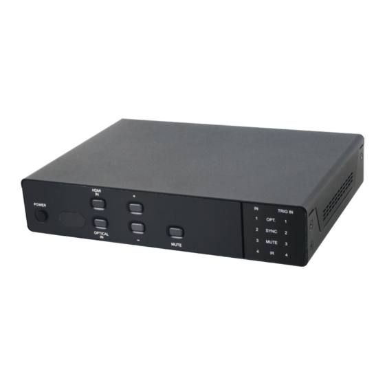
6. OPERATION CONTROLS AND FUNCTIONS 6.1 Front Panel HDMI TRIG IN OPT. POWER SYNC MUTE OPTICAL MUTE POWER & LED: Press this button to power the unit on (green LED) or place it into stand-by mode (red LED). Note: To force the IP mode to switch from Static to DHCP press and hold the power button for 3 seconds while the unit is ON and the LED will blink once to indicate the change has occurred. -
Page 9: Rear Panel
OPT IN LED: This LED will illuminate when optical is selected as an audio source. SYNC LED: This LED will illuminate when a valid HDMI source is detected from the currently selected input. MUTE LED: This LED will illuminate when audio is muted. When the currently selected audio input is in an unsupported format, or absent, this LED will blink and analog output will be automatically muted. - Page 10 USB: This slot is reserved for firmware update use only. CONTROL: Connect to an active Ethernet network with an RJ- 45 terminated cable to allow control of the unit via WebGUI and Telnet or to allow the unit to control other devices on the network. RS-232: Connect directly to your PC/laptop using the provided cable to send RS-232 commands to control the unit.
-
Page 11: Remote Control
6.3 Remote Control POWER POWER: Press this button to power the unit on or place it into stand-by mode. INPUT INPUT 1~4: Press the button corresponding to the input you wish to MUTE OPTICAL display. OPTICAL: Press this button to select the optical input as the live audio for the analog stereo outputs. -
Page 12: Rs-232 Protocol
6.5 RS-232 Protocol SWITCHER REMOTE CONTROLLER Assignment Assignment ► ◄ Baud Rate: 115200bps Data Bits: 8 Parity: None Flow Control: None Stop Bits: 1 6.6 RS-232 and Telnet Commands COMMAND DESCRIPTION HELP Show command list. Show command list. HELP N Show command descriptions. - Page 13 COMMAND DESCRIPTION MUTE N Set speaker mute status. N=0~1 0=Unmuted 1=Muted SPEAKER Show speaker input source. SPEAKER N Set speaker input source. N=0~1 0=HDMI 1=Optical AUDIOFMT Show HDMI audio EDID behavior. AUDIOFMT N Set HDMI audio EDID behavior. N=0~1 0=PCM 1=Bypass SOUNDSYS Show speaker audio format.
- Page 14 COMMAND DESCRIPTION SGATEWAY X.X.X.X Set Ethernet gateway. X=0~255 HTTPPORT N Set HTTP port. N=0~65535 RSTIP Reset IP configuration to DHCP. EDIDMODE Show EDID mode. EDIDMODE N Set EDID mode. N=0~1 0=Appoint 1=All EDIDALL Show EDID source for “All” mode. EDIDALL N Set EDID source for “All”...
- Page 15 COMMAND DESCRIPTION EDIDIN N1 N2 Set input N1’s EDID selection for “Appoint” mode. N1=1~4 N2=1~9 1=HDMI Output Native 2=8/2D/PCM/720p 3=8/2D/PCM/AC3/720p 4=8/2D/PCM/1080p 5=8/2D/PCM/AC3/1080p 6=8/2D/PCM/4K2K 7=8/2D/PCM/AC3/4K2K 8=8/2D/PCM/Y420 9=8/2D/AC3/Y420 HDCPIN Show the HDCP status for all inputs. HDCPIN N1 Show the HDCP status for input N1. N1=1~4 HDCPIN N1 N2 Set the HDCP support for input N1.
- Page 16 COMMAND DESCRIPTION INNAME N1 N2 Set HDMI input N1’s name. N1=1~4 N2={Name} (8 characters max, no spaces) OUTNAME Show HDMI output’s name. OUTNAME A N1 Set HDMI output’s name. N1={Name} (8 characters max, no spaces) RELAY N N1 Set Relay N’s state. N=1~4 (Relay Port) N1=OPEN, CLOSE, TOGGLE, STATUS IREMIT IR N1 N2 N3...
- Page 17 COMMAND DESCRIPTION COMCONF COM N1 Show the current COM port configuration. N1=1~2 (COM Port) COMCONF COM N1 N2 N3 N4 N5 Set the COM port configuration. N1=1~2 (COM Port) N2=4800, 9600, 19200, 38400, 57600, 115200 (Baud Rate) N3=5~8 (Data Bits) N4=0~2 (Parity) 0=None 1=Odd...
-
Page 18: Telnet Control
6.7 Telnet Control Before attempting to use telnet control, please ensure that both the unit and the PC/Laptop are connected to the same active networks. To access Telnet in Windows 7, click on the “Start” menu and type “cmd” in the search field, then press “Enter”. Under Windows XP go to the “Start”... - Page 19 This will connect us to the unit we wish to control. Type “help” to list the available commands. Note: • Commands will not be executed unless followed by a carriage return. Commands are not case-sensitive. • If the IP address is changed then the IP address required for Telnet access will also change accordingly.
-
Page 20: Webgui Control
6.8 WebGUI Control • Install the Device Discovery Tool Please obtain the Device Discovery software from your authorized dealer and save it in a directory where you can easily find it. Connect the unit and your PC/Laptop to the same active network and execute the Device Discovery software. -
Page 21: Routing Settings
• Login to the WebGUI Open a web browser on a PC/Laptop that is connected to an active network and type the device’s IP address into the web address entry bar. The login screen will appear and ask for a Username and Password. -
Page 22: Audio Settings
6.8.2 Audio Settings Click on the “Audio” tab to set the HDMI audio EDID format (Bypass or PCM) for the unit as well as the sound system format (mono or stereo), analog speaker source (optical or HDMI), volume level and mute setting for the connected analog speakers. -
Page 23: Macro Settings
6.8.4 Macro Settings Click on the “Macro Settings” tab to execute/edit the 8 available macros. These macros can be executed by activating the 4 input triggers on the back of the unit as well as via the WebGUI or Telnet. Each macro can contain up to 16 individual commands. -
Page 24: Command Settings
After selecting a command, you will need to choose the delay and interface for the command. (1) Delay(ms): This setting is the length of time to wait before sending the next command and is set in milliseconds. (2) Interface: The interface for sending commands can be set to the unit itself (SysCMD), to a specified IP address (TELNET), to a specified RS-232 port (COM), to a specified IR port (IR) or to trigger a relay port (Relay). -
Page 25: Network Settings
To create or edit a command, click on the "Edit" button next to the command you wish to change. Then, simply, enter the text command into the entry window that pops up. You may rename the command if you wish by changing the text in the “Command Label” field. Click on “Save Change”... -
Page 26: System Settings
6.8.7 System Settings Click on the “System Settings” tab to make changes to various system settings. From this tab you can change the WebGUI login password and power the unit on/off (stand-by). You may also save the full system configuration, including all macros, to your connected PC/ Laptop or restore them from a previously saved configuration. -
Page 27: Connection Diagram
7. CONNECTION DIAGRAM RS-232 Equipped PC/Laptop RS-232 Devices AV Receiver to be Controlled IR Outputs RS-232 Digital Audio RS-232 Input Input (Optical) Outputs Relay Outputs Powered RS-232 INFRARED OPT. IN COM 1 COM 2 RELAY OUT 1 2 3 4 Projector Screen OUT 1 OUT 2 OUT 3 OUT 4 OUT 5 CONTROL... -
Page 28: Specifications
8. SPECIFICATIONS 8.1 Technical Specifications Video Bandwidth 340 MHz/10.2 Gbps Input Ports 4×HDMI, 1×Optical Audio, 4×Trigger (5-pin Terminal Block) Output Ports 1×HDMI, 1×Stereo Speaker (Binding Post Pairs), 5×IR Blaster (3.5mm), 4×Relay (8-pin Terminal Block), 2×COM (3-pin Terminal Block) Control Interfaces 1×IP Control (RJ-45), 1×RS-232 (3.5mm) Supported Resolutions 480i@60Hz - 4K@60Hz (4:2:0, 8-bit) -
Page 29: Video Specifications
Storage Temperature −20˚C - 60˚C/−4˚F - 140˚F Relative Humidity 20 - 90% RH (No-condensing) Power Consumption 8.2 Video Specifications Supported Resolutions (Hz) Input Output 640×480@60/72/75 800×600@60/72/75 1024×768@60/70/75 1280×768@60 1280×800@60 1280×1024@60 ... -
Page 30: Audio Specifications
8.3 Audio Specifications Input Output Supported Audio Format HDMI Optical HDMI Speakers LPCM 2.0 LPCM 5.1 LPCM 7.1 Bitstream HD Bitstream 2×45W@4Ω<0.5%THD+N 2×12W@8Ω<0.5%THD+N Frequency Response <+/-1dB SNR>70dB@20Hz~20kHz A-weighted THD+N@1W<0.05%@1kHz THD+N@1W<0.1%@20Hz~20kHz... -
Page 31: Acronyms
9. ACRONYMS ACRONYM COMPLETE TERM Command Line Interface Digital Visual Interface EDID Extended Display Identification Data Graphical User Interface High-Definition HDCP High-bandwidth Digital Content Protection HDMI High-Definition Multimedia Interface HDTV High-Definition Television HTTP HyperText Transfer Protocol Infrared Local Area Network LPCM Linear Pulse-Code Modulation OLED... - Page 32 CYPRESS TECHNOLOGY CO., LTD. www.cypress.com.tw...
Need help?
Do you have a question about the CDPS-UH4H1HFS and is the answer not in the manual?
Questions and answers