
Related Manuals for CYP EL-7500V


Summary of Contents for CYP EL-7500V
- Page 1 EL-7500V HDM/VGA/YUV/CV to HDMI/VGA & HDBaseT (48V) Presentation Switch OPERATION MANUAL...
-
Page 3: Copyright Notice
DISCLAIMERS The information in this manual has been carefully checked and is believed to be accurate. CYP (UK) Ltd assumes no responsibility for any infringements of patents or other rights of third parties which may result from its use. CYP (UK) Ltd assumes no responsibility for any inaccuracies that may be contained in this document. -
Page 4: Safety Precautions
SAFETY PRECAUTIONS Please read all instructions before attempting to unpack, install or operate this equipment and before connecting the power supply. Please keep the following in mind as you unpack and install this equipment: • Always follow basic safety precautions to reduce the risk of fire, electrical shock and injury to persons. -
Page 5: Table Of Contents
CONTENTS 1. Introduction ...........6 2. Applications ...........6 3. Package Contents ........6 4. System Requirements ......7 5. Features ..........7 6. Operation Controls and Functions ..8 6.1 Front Panel ........... 8 6.2 Rear Panel ............. 9 6.3 Remote Control ........11 6.4 IR Cable Pinouts ........11 6.5 OSD Menu ..........12 6.6 WebGUI Control ........19 6.7 RS-232 Control ..........23... -
Page 6: Introduction
1. INTRODUCTION This multi-input scaler has HDMI, as well as Composite Video, Component Video, and PC (VGA) inputs which can be freely selected for output at a scaled resolution of the user’s choosing over the mirrored HDMI, HDBaseT and VGA outputs. This unit also includes analogue and digital audio out- puts to provide additional playback flexibility. -
Page 7: System Requirements
4. SYSTEM REQUIREMENTS HDMI, VGA, component or composite video source equipment such as media players, video game consoles, PCs, or set-top boxes. HDMI or VGA receiving equipment such as HDTVs, monitors or audio amplifiers. A compatible HDBaseT receiver with 48v PoH support is strongly recommended. -
Page 8: Operation Controls And Functions
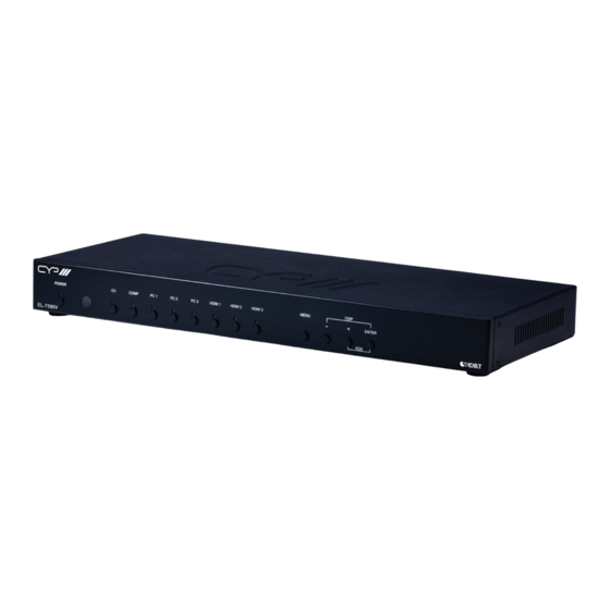
HDMI 2 HDMI 3 MENU ENTER EL-7500V POWER Button & LED: Press this button to power the unit on or place it into stand-by mode. The LED will be lit when the unit is receiving power. Note: The power switch on the back of the unit must also be in the “On”... -
Page 9: Rear Panel
6.2 Rear Panel OUTPUT INPUT SERVICE DC 24V EXTENDER BLASTER COAX. AUDIO AUDIO RS-232 BYPASS RS-232 OUTPUT CAT5e/6/7 HDMI PC/HD HDMI 1 HDMI 2 HDMI 3 PC 1 PC 2 PC 3 Cr/Pr Cb/Pb POWER CAT5e/6/7 OUT: Connect to a compatible HDBaseT Receiver with a single Cat.5e/6/7 cable for transmission of all data signals. - Page 10 AUDIO IN 1~3: Connect to the stereo analogue output of the device connected to the paired HDMI input port. Note: If the AUDIO SOURCE setting is set to “AUTO” and the HDMI input contains audio, it will have priority over the analogue input. PC IN 1~3: Connect to VGA source equipment such as a PC or laptop.
-
Page 11: Remote Control
6.3 Remote Control POWER: Press this button to power the unit on or place it into stand-by mode. HDMI 1~3/PC 1~3/CV/COMP: Press any of these buttons to switch immediately to the corresponding input. MENU: Press this button to enter the OSD menu. EXIT: Press this button to exit the menu or the current selection in the OSD menu. -
Page 12: Osd Menu
6.5 OSD Menu All functions of this unit can be controlled by using the OSD (On Screen Display) which is activated by pressing the MENU button on the front of the unit. Use the + (Plus), − (Minus), and ENTER buttons to navigate the OSD menu. - Page 13 DISPLAY 2ND LEVEL 3RD LEVEL 4TH LEVEL Output 640×480 60 800×600 60 1024×768 60 1280×768 60 1360×768 60 1280×720 60 1280×800 60 1280×1024 60 1440×900 60 1400×1050 60 1680×1050 60 1600×1200 60 1920×1080 60 1920×1200 60 1280×720p 60 Output 1920×1080i 60 1920×1080p 60 720×576p 50 1280×720p 50...
- Page 14 DISPLAY 2ND LEVEL 3RD LEVEL 4TH LEVEL Size (Cont.) Under 2 Under 1 Mode Info INFO Input HDCP PC (PC Sources Only) Auto Setup H Position V Position Phase Clock WXGA/XGA WXGA Reset 1) Output: Selects the scaled output resolution to use. 2) Size: Selects the aspect ratio to use when outputting the source.
- Page 15 COLOR 2ND LEVEL 3RD LEVEL 4TH LEVEL 0~60 (30) Contrast 0~60 (30) Brightness 0~1023 (512) Color 0~1023 (512) 0~1023 (512) 0~1023 (512) R Offset 0~1023 (512) G Offset 0~1023 (512) B Offset 0~60 (30) Saturation 0~60 (30) 0~30 (0) Sharpness Middle High 1) Contrast: Provides control over the overall contrast of the scaled...
- Page 16 AUDIO 2ND LEVEL 3RD LEVEL 0~100 (100) Volume Delay 40ms 110ms 150ms Sound Mute AUTO Source (For HDMI inputs only) Ext. 1) Volume: Provides control over the volume level of all audio outputs. 2) Delay: This control sets the amount of audio delay to use, in milliseconds.
- Page 17 SETUP 2ND LEVEL 3RD LEVEL Factory Reset Key Lock Power Save DHCP IP Mode Static IP Address: 192.168.0.1 Set Static IP Subnet Mask: 255.255.255.0 Def. Gateway: 192.168.1.254 Free Run Color Black BLUE 1) Factory Reset: Selecting this will reset the unit’s settings back to their factory defaults.
- Page 18 INFORMATION 2ND LEVEL 3RD LEVEL Input Output [Current Status Details] Revision IP Address 1) Information: This screen displays information about the unit’s current state, input and output status, IP address, as well as the current firmware version.
-
Page 19: Webgui Control
6.6 WebGUI Control Device Discovery APP Please obtain the “Device Discovery” software from your authorised dealer and save it in a directory where you can easily find it. Connect the unit and your PC/Laptop to the same active network and ex- ecute the “Device Discovery”... - Page 20 WebGUI Overview All primary functions of this unit are controllable via the built-in WebGUI. These controls are presented within a single main page. After connect- ing to the unit’s IP address in a web browser, the main control web page will display, allowing direct control of the unit.
- Page 21 INPUT This section allows for control of input selection. STATUS This section provides information about the unit’s current input, and output as well as the current Firmware Revision. DISPLAY This section allows for control over the output resolution, aspect ratio, HDCP behavior of the HDMI inputs, as well as configuring the information OSD’s behavior.
- Page 22 adjusted using the front panel buttons other than disabling the key lock setting itself. - POWER SAVE: Enabling the power save function will cause the unit to automatically switch into stand-by mode if there is no live signal, and no user interaction for a period of 3 minutes. FIRMWARE UPDATE This section allows for new firmware to be uploaded into the unit.
-
Page 23: Rs-232 Control
6.7 RS-232 Control UNIT TERMINAL SERIAL PORT SETTINGS Pinout Pinout Baud Rate 115200 Data Bits Parity Bit None Stop Bits Flow Control None 6.8 Telnet Control Before attempting to use Telnet control, please ensure that both the unit and the PC are connected to the same active networks. To Access the Command Line Interface (CLI) Click Start, type “cmd”... -
Page 24: Rs-232 And Telnet Commands
6.9 RS-232 and Telnet Commands COMMAND DESCRIPTION & PARAMETERS Show the full command list. HELP Show the full command list. S POWER N1 Turn the unit on or off (stand-by mode). Available values for N1: [Off (Stand-by mode)] [On] R POWER Shows the current power state of the unit. - Page 25 COMMAND DESCRIPTION & PARAMETERS S OUTPUT N1 Set the scaled output resolution. Available values for N1: [640×480@60Hz] [800×600@60Hz] [1024×768@60Hz] [1280×768@60Hz] [1360×768@60Hz] [1280×720@60Hz] [1280×800@60Hz] [1280×1024@60Hz] [1440×900@60Hz] [1400×1050@60Hz] [1680×1050@60Hz] [1600×1200@60Hz] [1920×1080@60Hz] [1920×1200@60Hz] [480p@60Hz] [720p@60Hz] [1080i@60Hz] [1080p@60Hz] [576p@50Hz] [720p@50Hz] [1080i@50Hz] [1080p@50Hz] Note: Resolutions 0~13 are encoded using the RGB color space. Resolu- tions 14~21 are encoded using the YUV color space.
- Page 26 COMMAND DESCRIPTION & PARAMETERS S SIZE N1 Set the output aspect ratio. Available values for N1: [Overscan] [Full] [Follow Input] [Pan & Scan] [Letterbox] [Underscan 2] [Underscan 1] R SIZE Show the current output aspect ratio. S INFO MODE N1 Enable, disable, or set a short timeout for the OSD information dis- play.
- Page 27 COMMAND DESCRIPTION & PARAMETERS S PC AUTO 1 Activate the VGA auto setup function for the current VGA input. S PC H POSITION N1 Set the horizontal position for VGA inputs. Available values for N1: N1 = 0 ~ 60 [Horizontal position] R PC H POSITION Show the current horizontal position for VGA inputs.
- Page 28 COMMAND DESCRIPTION & PARAMETERS S PC WXGA XGA N1 Set whether XGA or WXGA has detection priority. (VGA inputs only) Available values for N1: [WXGA has priority] [XGA has priority] R PC WXGA XGA Show the current XGA/WXGA detection priority setting. S CONTRAST N1 Set the output’s contrast level.
- Page 29 COMMAND DESCRIPTION & PARAMETERS R COLOR GREEN Show the current green output level. S COLOR BLUE N1 Set the output’s blue level. N1 = 0 ~ 1023 [Blue level] R COLOR BLUE Show the current blue output level. S COLOR RED OFFSET N1 Set the output’s red offset level.
- Page 30 COMMAND DESCRIPTION & PARAMETERS S HUE N1 Set the output’s hue adjustment value. N1 = 0 ~ 60 [Hue] R HUE Show the output’s current hue adjustment value. S SATURATION N1 Set the output’s saturation level. N1 = 0 ~ 60 [Saturation] R SATURATION Show the output’s current saturation level.
- Page 31 COMMAND DESCRIPTION & PARAMETERS S VOLUME N1 Set the audio output volume level. N1 = 0~100 [Volume level] R VOLUME Show the current volume level. S AUDIODELAY N1 Set the global audio delay setting. Available values for N1: [Off ] [40ms] [110ms] [150ms]...
- Page 32 COMMAND DESCRIPTION & PARAMETERS R HDMIAUDIO Show the current HDMI audio source selection setting. S KEY LOCK N1 Enable or disable the front panel key lock function. Available values for N1: [Enable Key Lock] [Disable key lock] R KEY LOCK Show the current front panel key lock state.
- Page 33 COMMAND DESCRIPTION & PARAMETERS R STATIC IP ADDR Show the current IP address. S SUB MASK N1 Set the static netmask address. N1 = X.X.X.X [X = 0 ~ 255] R SUB MASK Show the current netmask. S GATE WAY N1 Set the static gateway address.
-
Page 34: Connection Diagram
7. CONNECTION DIAGRAM RS-232 Control System AV Receiver RS-232 Digital & Analog Audio Outputs RS-232 Media Player RS-232 Controlled Network Device Switch Component Video & Analog Audio Inputs 60° 1.5m Power Supply OUTPUT INPUT SERVICE DC 24V EXTENDER BLASTER COAX. AUDIO AUDIO RS-232 BYPASS... -
Page 35: Specifications
8. SPECIFICATIONS 8.1 Technical Specifications HDMI Bandwidth 165MHz/4.95Gbps HDBaseT Bandwidth 340MHz/10.2Gbps Input Ports 3×HDMI 3×VGA (HD-15) 1×YPbPr (RCA) 1×CV (RCA) 6×Stereo (3.5mm) 2×Stereo (4×RCA) Output Ports 1×HDMI 1×HDBaseT (Cat.5e/6/7) 1×VGA (HD-15) 1×S/PDIF (RCA) 1×Stereo (3.5mm) Pass-through Ports 1×IR Extender (3.5mm) 1×IR Blaster (3.5mm) 1×RS-232 (9-pin D-sub) Pass-through/Control Port... -
Page 36: Video Specifications
Dimensions 432mm×44mm×174mm (W×H×D) [Case Only] 432mm×49mm×183mm (W×H×D) [All Inclusive] Weight 2,150g Chassis Material Metal Silkscreen Color Black Operating Temperature 0 ˚C–40 ˚C/32 ˚F–104 ˚F Storage Temperature -20 ˚C–60 ˚C/-4 ˚F–140 ˚F Relative Humidity 20–90% RH (Non-condensing) Power Consumption 24.77W 8.2 Video Specifications Support Resolution/Timing (Hz) HDMI Input... -
Page 37: Audio Specifications
Support Resolution/Timing (Hz) HDMI Input PC Input Output 1600×1200p@60 1680×1050p@60/60 (RB) 60Hz 1920×1080p@60 1920×1200p@60 (RB) 1440×576i@50 × × 1440×480i@59.94/60 × × 720×480p@59.94/60 × × 720×576p@50 × ... -
Page 38: Acronyms
9. ACRONYMS ACRONYM COMPLETE TERM Analogue-to-Digital Converter Cat.5e Category 5 (enhanced) cable Cat.6 Category 6 cable Cat.7 Category 7 cable Consumer Electronics Control Command-Line Interface COMP Component Video Digital-to-Analogue Converter Digital Visual Interface EDID Extended Display Identification Data Graphical User Interface High-Definition HDCP High-bandwidth Digital Content Protection... - Page 39 ACRONYM COMPLETE TERM Power over HDBaseT Power Sourcing Equipment S/PDIF Sony/Philips Digital Interface Format Signal-to-Noise Ratio THD+N Total Harmonic Distortion plus Noise Ultra-High-Definition UHDTV Ultra-High-Definition Television Universal Serial Bus Video Graphics Array WUXGA (RB) Widescreen Ultra Extended Graphics Array (Reduced Blanking)
- Page 40 CYP (UK) Ltd., Unit 7, Shepperton Business Park, Govett Avenue, Shepperton, Middlesex, TW17 8BA Tel: +44 (0) 20 3137 9180 | Fax: +44 (0) 20 3137 6279 Email: sales@cypeurope.com www.cypeurope.com v1.00...
Need help?
Do you have a question about the EL-7500V and is the answer not in the manual?
Questions and answers