
Related Manuals for ABB RPBA-01


Summary of Contents for ABB RPBA-01
- Page 1 ABB Drives User’s Manual PROFIBUS DP Adapter Module RPBA-01 Phone: 800.894.0412 - Fax: 888.723.4773 - Web: www.clrwtr.com - Email: info@clrwtr.com...
- Page 2 Phone: 800.894.0412 - Fax: 888.723.4773 - Web: www.clrwtr.com - Email: info@clrwtr.com...
- Page 3 PROFIBUS DP Adapter Module RPBA-01 User’s Manual 3AFE 64504215 REV F EN EFFECTIVE: 20.06.2005 © 2005 ABB Oy. All Rights Reserved. Phone: 800.894.0412 - Fax: 888.723.4773 - Web: www.clrwtr.com - Email: info@clrwtr.com...
- Page 4 Phone: 800.894.0412 - Fax: 888.723.4773 - Web: www.clrwtr.com - Email: info@clrwtr.com...
-
Page 5: Safety Instructions
Safety instructions Overview This chapter states the general safety instructions that must be followed when installing and operating the RPBA-01 PROFIBUS DP Adapter module. The material in this chapter must be studied before attempting any work on, or with, the unit. - Page 6 Safety instructions Phone: 800.894.0412 - Fax: 888.723.4773 - Web: www.clrwtr.com - Email: info@clrwtr.com...
-
Page 7: Table Of Contents
PROFIBUS standard ......... . 15 The RPBA-01 PROFIBUS DP Adapter module ..... . 16 Compatibility . - Page 8 Mechanical installation ........27 Mounting .
- Page 9 RPBA-01 ........
- Page 10 Table of contents Phone: 800.894.0412 - Fax: 888.723.4773 - Web: www.clrwtr.com - Email: info@clrwtr.com...
-
Page 11: Introduction
Safety instructions are featured in the first few pages of this manual. Overview contains a short description of the PROFIBUS protocol and the RPBA-01 PROFIBUS DP Adapter module, a delivery checklist, and information on the manufacturer’s warranty. Quick start-up guide contains a short description of how to set up the RPBA-01 PROFIBUS DP Adapter module. - Page 12 RPBA-01 module using the PROFIBUS-DP (DP-V0) protocol. DP-V1 communication contains a description of how data is transmitted through the RPBA-01 module using the DP-V1 extension of the PROFIBUS DP protocol. Fault tracing explains how to trace faults with the status LEDs on the RPBA-01 module.
-
Page 13: Terms Used In This Manual
RPBA-01 PROFIBUS DP Adapter module The RPBA-01 PROFIBUS DP Adapter module is one of the optional fieldbus adapter modules available for ABB drives. The RPBA-01 is a device through which an ABB drive is connected to a PROFIBUS network. Parameter A parameter is an operating instruction for the drive. - Page 14 Introduction Phone: 800.894.0412 - Fax: 888.723.4773 - Web: www.clrwtr.com - Email: info@clrwtr.com...
-
Page 15: Overview
Overview Overview This chapter contains a short description of the PROFIBUS standard and the RPBA-01 PROFIBUS DP Adapter module, a delivery checklist and warranty information. PROFIBUS standard PROFIBUS is an open serial communication standard that enables data exchange between all kinds of automation components. -
Page 16: The Rpba-01 Profibus Dp Adapter Module
The RPBA-01 PROFIBUS DP Adapter module The RPBA-01 PROFIBUS DP Adapter module is an optional device for ABB drives which enables the connection of the drive to a PROFIBUS network. The drive is considered as a slave on the PROFIBUS network. Through the RPBA-01 PROFIBUS DP Adapter module, it is possible to: •... -
Page 17: Compatibility
Figure 1. The construction of the PROFIBUS link and the RPBA-01 Adapter module. Compatibility The RPBA-01 is compatible with all master stations that support the PROFIBUS DP protocol. Delivery check The option package for the RPBA-01 PROFIBUS DP Adapter module contains: •... -
Page 18: Warranty And Liability Information
(12) months after installation or twenty-four (24) months from date of manufacturing, whichever first occurs. The local ABB office or distributor may grant a warranty period different to the above and refer to local terms of liability as defined in the supply contract. -
Page 19: Quick Start-Up Guide
Quick start-up guide Overview This chapter presents the steps to take during the start-up of the RPBA-01 PROFIBUS DP Adapter Module. For more detailed information, see the chapters Mechanical installation, Electrical installation, and Programming elsewhere in this manual. WARNING! Follow the safety instructions given in this manual and the Hardware Manual of the drive. - Page 20 • Select the operation mode (PROFIDRIVE, i.e. Generic, or VENDOR SPECIFIC, i.e. ABB Drives). Quick start-up guide Phone: 800.894.0412 - Fax: 888.723.4773 - Web: www.clrwtr.com - Email: info@clrwtr.com...
-
Page 21: Mechanical And Electrical Installation
(If the node address is set by software, set the switches to the “0” position.) • Set the bus termination switch to the desired position. • Insert the RPBA-01 into its specified slot in the drive (SLOT2 for ACS550, SLOT1 for ACS800). • Fasten the two screws. - Page 22 With an ACS550 drive, set parameter 98.02 COMM. MODULE LINK to EXT FBA. With an ACS800, set parameter 98.02 COMM. MODULE LINK to FIELDBUS and parameter 98.07 COMM PROFILE to ABB DRIVES or GENERIC (according to PLC hardware configuration).
-
Page 23: Parameter Setting Examples
51.27 FBA PAR REFRESH REFRESH *Read-only or automatically detected The RPBA-01 uses data-consistent communication, meaning that the whole data frame is transmitted during a single program cycle. Some PLCs handle this internally, but others must be programmed to transmit data-consistent telegrams. For example, Quick start-up guide Phone: 800.894.0412 - Fax: 888.723.4773 - Web: www.clrwtr.com - Email: info@clrwtr.com... - Page 24 Siemens Simatic S7 requires the use of special functions SFC15 and SFC14. The start/stop commands and reference are according to the PROFIdrive profile. (See the PROFIBUS state machine on page 77.) The reference value ±16384 (4000h) corresponds to the nominal speed of the motor (parameter 99.08) in forward and reverse directions.
- Page 25 ABB DRIVES profile (Vendor-specific) with PPO Type 2 (DP-V0) Drive parameter Setting ACS800 ACS550 10.01 EXT1 STRT/STP/DIR COMM.CW COMM 10.02 EXT2 STRT/STP/DIR COMM.CW COMM 11.02 EXT1/EXT2 SELECT COMM.CW COMM 11.03 EXT REF1 SELECT COMM. REF COMM 16.01 RUN ENABLE COMM.CW COMM 16.04 FAULT RESET SEL...
- Page 26 From the PLC programming point, the ABB DRIVES profile is similar to the Generic profile as shown in the first example. The start/stop commands and reference are according to the ABB DRIVES profile. (See the drive manuals for more information.) If REF1 is used, the reference value ±20000 (decimal)
-
Page 27: Mechanical Installation
Hardware Manual. Mounting The RPBA-01 is to be inserted into its specific position in the drive. The module is held in place with plastic retaining clips and two screws. The screws also provide the earthing of the I/O cable shield connected to the module, and interconnect the GND signals of the module and the control board of the drive. - Page 28 Mechanical installation Phone: 800.894.0412 - Fax: 888.723.4773 - Web: www.clrwtr.com - Email: info@clrwtr.com...
-
Page 29: Electrical Installation
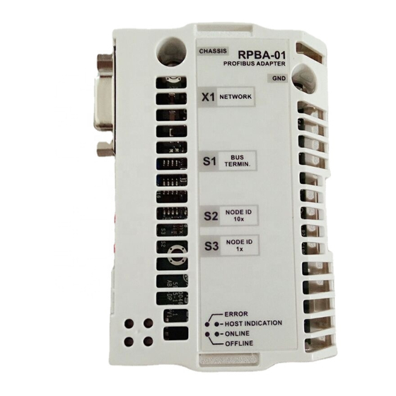
Avoid parallel runs. Use bushings at cable entries. Bus termination The DIP switch on the front of the RPBA-01 module is used to switch on bus termination. Bus termination prevents signal reflections from the cable ends. Bus termination must be set to ON if the module is the last or first module on the network. -
Page 30: Node Selection
Note: The built-in termination circuitry of the RPBA-01 is of the active type, so the module has to be powered for the termination to work. If the module needs to be switched off during operation of the network, the bus can be terminated by connecting a 220 ohm, 1/4 W resistor between the A and B lines. -
Page 31: Profibus Connection
PROFIBUS connection The bus cable is connected to connector X1 on the RPBA-01. The connector pin allocation described below follows the PROFIBUS standard. Description Not used Not used Data positive (Conductor 1 in twisted pair). Request To Send Isolated ground... - Page 32 In the example below a recommended Siemens 6ES7 972- 0BA12-0XA0 connector (not included in the delivery) is connected to the RPBA-01 module. The cable is a standard PROFIBUS cable consisting of a twisted pair and screen. Siemens 6ES7 972-0BA12-0XA0 connector...
-
Page 33: Programming
(GSD) file. For DP-V0 communication, the file is available from profibus website or an ABB representative (the filename is ABB_0812.GSD). For DP-V1 communication, the type definition (GSD) file is available from an ABB representative (the filename is ABB10812.GSD). Please refer to the master station documentation for more information. - Page 34 ‘Fieldbus Adapter parameter refresh’ command from the drive. Data transfer rates supported The RPBA-01 supports the following PROFIBUS communication speeds: 9.6 kbit/s, 19.2 kbit/s, 45.45 kbit/s, 93.75 kbit/s, 187.5 kbit/s, 500 kbit/s, 1.5 Mbit/s, 3 Mbit/s, 6 Mbit/s, 12 Mbit/s.
- Page 35 The value is automatically updated (Read-only). Note: Set also the extended Parameter Data (see page 67) to ensure proper operation of the RPBA-01 with the drive. 1 MODULE TYPE This parameter shows the module type as detected by the drive.
- Page 36 4 PPO-TYPE This parameter indicates the detected PPO message type for the PROFIBUS communication. See Figures in the chapters DP-V0 communication DP-V1 communication respectively for the supported PPO message types. 5 PZD3 OUT This parameter represents process data word 3 of the PPO type received by the drive over the PROFIBUS network.
-
Page 37: Control Locations
ABB drives can receive control information from multiple sources including digital inputs, analogue inputs, the drive control panel and a communication module (e.g. RPBA-01). ABB drives allow the user to separately determine the source for each type of control information (Start, Stop, Direction, Reference, Fault Reset, etc.). - Page 38 Programming Phone: 800.894.0412 - Fax: 888.723.4773 - Web: www.clrwtr.com - Email: info@clrwtr.com...
-
Page 39: Dp-V0 Communication
DP-V0 communication Overview This chapter describes the PROFIBUS messaging used in the communication with the drive when the RPBA-01 module is in DP- V0 mode. PROFIBUS DP The RPBA-01 module supports the PROFIBUS-DP protocol according to EN 50170 standard. PROFIBUS DP is a distributed I/O system which enables the master to use a large number of peripheral modules and field devices. -
Page 40: Communication Start-Up
Calculated by multiplying the Hex value with t (time required for transmitting one bit). 4 - 5 0812h Vendor Identification (for the RPBA-01: 0812h) Group Identification DP-V0 communication Phone: 800.894.0412 - Fax: 888.723.4773 - Web: www.clrwtr.com - Email: info@clrwtr.com... - Page 41 Operation mode. Determines which control/status word and reference/actual values are used. 00 = PROFIDRIVE (i.e. Generic drive profile) 01 = VENDOR SPECIFIC (i.e. ABB Drives profile) (default). With this setting, • Fail-safe mode ‘STOP’ equals ‘LAST SPEED’ • the control word is forwarded unchanged to the drive •...
- Page 42 25 - 26 0-65536 Fail-safe, PZD8 27 - 28 0-65536 Fail-safe, PZD9 29 - 30 0-65536 Fail-safe, PZD10 The extended Parameter Data bytes are configured via the PROFIBUS network configuration tool. The functions are defined in the GSD file. SAP 62 (Chk_Cfg) SAP 62 selects the PPO type to be used.
- Page 43 SAP 60 (Slave_Diag) This SAP gives diagnostic information on the slave station. Diag_Data (Diagnostic Data) Type: Octet String - Length: 6 (Standard) + 2 (Extended Diagnosis) Byte Description Station_Status_1 Diag.Station_Non_Existent (Set by Master, reset by Slave) Slave not found Diag.Stagion_Not_Ready (Set by Slave) Slave not ready for data exchange Diag.Cfg_Fault (Set by Slave) Received configuration data does not match original configuration data...
- Page 44 0 0 0 0 0 Reserved Diag.Ext_Diag_Overflow (Set by Slave) Diag.Master_Add The address of the master that parameterised this slave 4 - 5 Ident_Number (for RPBA-01: 0812h) Ext_Diag_Data The number of bytes reserved for Extended Diagnosis (including this byte) Fixed to 2...
-
Page 45: Ppo Message Types
PPO message types Parameter Process data Fixed area Freely mappable area identification DW1.1 DW1.2 DW1.3 DW3.1 DW3.2 DW3.3 DW5.1 DW5.2 DW5.3 DW7.1 OUT area REF PZD3 PZD4 PZD5 PZD6 PZD7 PZD8 PZD9 PZD10 VALUE IN area VALUE PZD3 PZD4 PZD5 PZD6 PZD7 PZD8 PZD9 PZD10 DW2.1 DW2.2 DW2.3 DW4.1 DW4.2 DW4.3 DW6.1 DW6.2 DW6.3 DW8.1 Type 1 Type 2... -
Page 46: The Control Word And The Status Word
ABB drives can receive control information from multiple sources including analogue and digital inputs, the drive control panel and a communication module (e.g. RPBA-01). In order to have the drive controlled through PROFIBUS, the communication module must be defined as the source for control information, e.g. Reference. - Page 47 master as Actual Values depends on the selected function, refer to the drive documentation. In PROFIdrive mode, the actual speed (ACT) in hexadecimal (0…4000h) corresponds to 0…‘motor nominal speed’. Table 7. The Control Word (PROFIBUS Parameter 967). The upper case boldface text refers to the states shown in Figure 9.
- Page 48 Name Value Proceed to STATE/Description RAMP_IN_ Normal operation. Proceed to OPERATING ZERO Force Ramp Function Generator input to zero Note: The function of this bit may depend on the ramp parameter settings of the drive. See the drive documentation. 0 ⇒ 1 Fault reset if an active fault exists. Proceed to SWITCH- RESET ON INHIBIT.
- Page 49 Name Value STATE/Description OFF_2_STA OFF2 inactive OFF2 ACTIVE OFF_3_STA OFF3 inactive OFF3 ACTIVE SWC_ON_INHIB SWITCH-ON INHIBIT ACTIVE SWITCH-ON INHIBIT NOT ACTIVE ALARM Warning/Alarm No Warning/Alarm AT_SETPOINT OPERATING. Actual value equals reference value (i.e. is within tolerance limits) Actual value differs from reference value (= is outside tolerance limits) REMOTE Drive control location: REMOTE...
- Page 50 SWITCH-ON MAINS OFF INHIBIT (SW Bit6=1) PROFIdrive OFF1 (CW Bit0=0) Power ON State Machine NOT READY CW = Control Word TO SWITCH ON (SW Bit0=0) A B C D SW = Status Word = Speed = Input Current (CW=xxxx xxxx xxxx x110) RFG = Ramp Function (CW Bit3=0) Generator...
-
Page 51: Parameter Handling In Cyclic Communication (Dp)
Parameter handling in cyclic communication (DP) In cyclic PROFIBUS DP communication, parameter data is transferred in PPO message types 1, 2 and 5 (see Figure 6.). The Parameter Identification part consists of eight bytes (see below). Parameter Identification Process Data CW REF VALUE (PD1, PD2...) - Page 52 Response label (Acknowledgement from Slave to Master) Ackn. Function No response Transfer parameter value (word) Transfer parameter value (double word) Transfer description element Transfer parameter value (array word) Transfer parameter value (array double word) Transfer number of array elements Task cannot be executed, followed by error number 0 = Illegal parameter number 1 = Parameter value cannot be changed 2 = Lower or upper limit violated...
- Page 53 The allocation of data sets, drive parameters and PROFIdrive parameters to the Parameter Identification part of the PPO type is shown below. The Index column corresponds to the parameter number (PNU) in the ID part of Parameter Identification. The Sub- index column corresponds to the IND part of Parameter Identification.
- Page 54 Note: Continuous (cyclic) writing of PROFIdrive parameters should be avoided as the values of these parameters are stored in the flash memory of the RPBA-01. The estimated lifetime of the flash memory is 1,000,000 program/erase cycles, and continuous writing will cause the memory to fail prematurely.
- Page 55 Example 1: Reading a drive parameter (or data set) To determine the parameter number and subindex for drive parameter reading, multiply the parameter number by one hundred and then convert it to hexadecimal. The low byte is the subindex (IND), and the high byte is the parameter number (PNU). For example reading parameter 84.11 INPUT 1 from the drive: 84.11 ×...
- Page 56 Example 2: Writing a drive parameter (or data set) To determine the parameter number and subindex for drive parameter writing, multiply the parameter number by one hundred and then convert it to hexadecimal. The low byte is the subindex (IND), and the high byte is the parameter number (PNU). For example write parameter 12.02 CONSTANT SPEED.1: 12.02 ×...
- Page 57 Example 3: Reading a PROFIdrive parameter (word) In this example, PROFIBUS Parameter No. 918 is used to read the station number of the slave. Request (Parameter value read) Parameter Number (918 Dec) Param. Value Request 13 96 00 00 00 00 00 00 04 7F 34 15 Read: Response 13 96 00 00 00 00 00 02 03 37 34 15 Param.
- Page 58 Example 4: Writing a PROFIdrive parameter (word) In this example, current parameter settings are saved to the FLASH memory of the drive. This is done by setting the value of PROFIBUS Parameter No. 971 (3CBh) to 1. Note that the drive always observes the Control Word (CW) and Reference (REF) bytes.
- Page 59 See also the User’s Manual of the drive for drive specific fault codes. The implementation of the PROFIdrive profile in the RPBA-01 supports the storage of the active and the five latest occurred different faults in the fault buffer. The fault codes can be accessed...
- Page 60 Example 6: Configuring the process data written to the drive PROFIBUS parameter 915 can be used to define which data is written cyclically to a drive parameter as application-specific process data. In the example below, the value of drive parameter 12.02 CONSTANT SPEED 1 (4B2h) is selected to be taken from PZD3.
- Page 61 Example 7: Configuring the process data read from the drive PROFIBUS Parameter No. 916 can be used to define which data is read cyclically from the drive as application-specific process data. In the example below, drive parameter 1.04 CURRENT (68h) is selected to be transmitted by the drive as PZD3.
- Page 62 DP-V0 communication Phone: 800.894.0412 - Fax: 888.723.4773 - Web: www.clrwtr.com - Email: info@clrwtr.com...
-
Page 63: Dp-V1 Communication
DP-V1 communication Overview This chapter describes the PROFIBUS messaging used in the communication with the drive when the RPBA-01 module is in DP- V1 mode. PROFIBUS DP The RPBA-01 module supports the PROFIBUS-DP protocol according to EN 50170 standard. PROFIBUS DP is a distributed I/O system which enables the master to use a large number of peripheral modules and field devices. -
Page 64: Communication Start-Up
Calculated by multiplying the hex value with t (time required for transmitting one bit). 4 - 5 0812h Vendor Identification (for the RPBA-01: 0812h) Group Identification DP-V1 communication Phone: 800.894.0412 - Fax: 888.723.4773 - Web: www.clrwtr.com - Email: info@clrwtr.com... - Page 65 DPV1_Status_1 x 0 x 0 0 x x x Dis_Start_Control (Disable Stop-Bit Control) 0 = Start bit monitoring in receiver enabled 1 = Start bit monitoring in receiver disabled Dis_Stop_Control (Disable Stop-Bit Control) 0 = Stop bit monitoring in receiver enabled 1 = Stop bit monitoring in receiver disabled WD_Base (Watchdog time base) 0 = 10 ms...
- Page 66 DPV1_Status_2 x x x x x x 0 x Chk_Cfg_Mode 0 = Chk_Cfg according to EN 50170 (default state) 1 = User-specific evaluation of Chk_Cfg Reserved. To be parameterised with ‘0’. Enable_Update_Alarm 0 = Enable_Update_Alarm disabled 1 = Enable_Update_Alarm enabled (Not supported) Enable_Status_Alarm 0 = Enable_Status_Alarm disabled 1 = Enable_Status_Alarm enabled (Not supported)
- Page 67 Operation mode. Determines which control/status word and reference/actual values are used. 00 = PROFIDRIVE (i.e. Generic drive profile) 01 = VENDOR SPECIFIC (i.e. ABB Drives profile) (default). With this setting, • Fail-safe mode ‘STOP’ equals ‘LAST SPEED’ • the control word is forwarded unchanged to the drive •...
- Page 68 DP-V1 parameter read/write service. The PPO type can be changed during runtime. However, the RPBA-01 will go offline while the configuration is being updated. DP-V1 communication Phone: 800.894.0412 - Fax: 888.723.4773 - Web: www.clrwtr.com - Email: info@clrwtr.com...
- Page 69 SAP 60 (Slave_Diag) This SAP gives diagnostic information on the slave station. Diag_Data (Diagnostic Data) Type: Octet String - Length: 6 (Standard) + 2 (Extended Diagnosis) Byte Description Station_Status_1 Diag.Station_Non_Existent (Set by Master, reset by Slave) Slave not found Diag.Stagion_Not_Ready (Set by Slave) Slave not ready for data exchange Diag.Cfg_Fault (Set by Slave) Received configuration data does not match original config.
- Page 70 0 0 0 0 Reserved Diag.Ext_Diag_Overflow (Set by Slave) Diag.Master_Add The address of the master that parameterised this slave 4 - 5 Ident_Number (for RPBA-01: 0812h) Header Byte Status Type = Status Message (0x81) Slot Number (0x00) Specifier (0x00) Communication Diagnostic...
-
Page 71: Ppo Message Types
PPO message types Parameter Process data Fixed area Freely mappable area identification DW1.1 DW1.2 DW1.3 DW3.1 DW3.2 DW3.3 DW5.1 DW5.2 DW5.3 DW7.1 OUT area REF PZD3 PZD4 PZD5 PZD6 PZD7 PZD8 PZD9 PZD10 VALUE IN area VALUE PZD3 PZD4 PZD5 PZD6 PZD7 PZD8 PZD9 PZD10 DW2.1 DW2.2 DW2.3 DW4.1 DW4.2 DW4.3 DW6.1 DW6.2 DW6.3 DW8.1 Type 1 DP-V0... -
Page 72: The Control Word And The Status Word
ABB drives can receive control information from multiple sources including analogue and digital inputs, the drive control panel and a communication module (e.g. RPBA-01). In order to have the drive controlled through PROFIBUS, the communication module must be defined as the source for control information, e.g. Reference. - Page 73 master as Actual Values depends on the selected function, refer to the drive documentation. In PROFIdrive mode, the actual speed (ACT) in hexadecimal (0…4000h) corresponds to 0…‘motor nominal speed’. Table 11. The Control Word (PROFIBUS Parameter 967). The upper case boldface text refers to the states shown in Figure 13.
- Page 74 Name Value Proceed to STATE/Description RAMP_IN_ Normal operation. Proceed to OPERATING ZERO Force Ramp Function Generator input to zero Note: The function of this bit may depend on the ramp parameter settings of the drive. See the drive documentation. 0 ⇒ 1 Fault reset if an active fault exists. Proceed to SWITCH- RESET ON INHIBIT.
- Page 75 Table 12. The Status Word (PROFIBUS Parameter 968). The upper case boldface text refers to the states shown in Figure 13. Name Value STATE/Description RDY_ON READY TO SWITCH ON NOT READY TO SWITCH ON RDY_RUN READY TO OPERATE OFF1 ACTIVE RDY_REF ENABLE OPERATION DISABLE OPERATION...
- Page 76 Name Value STATE/Description Vendor-specific bit as defined by PROFIdrive parameter 939. (See the drive documentation.) Vendor-specific bit as defined by PROFIdrive parameter 940. (See the drive documentation.) Vendor-specific bit as defined by PROFIdrive parameter 941. (See the drive documentation.) Vendor-specific bit as defined by PROFIdrive parameter 942.
- Page 77 SWITCH-ON MAINS OFF INHIBIT (SW Bit6=1) PROFIBUS OFF1 (CW Bit0=0) Power ON State Machine NOT READY CW = Control Word TO SWITCH ON (SW Bit0=0) A B C D SW = Status Word = Speed = Input Current (CW=xxxx xxxx xxxx x110) RFG = Ramp Function (CW Bit3=0) Generator...
-
Page 78: Dp-V1 Read/Write Request Sequence
If the write request is valid, the RPBA-01 acknowledges it with DP- V1 write response code 5Fh with no data. The master will then send a read request. If the RPBA-01 is still busy performing the internal parameter request, it will return a negative response with the DP-V1 error code B5h (State conflict). - Page 79 RPBA-01 has the PROFIdrive response data ready. If the write request is invalid, a negative response is returned with a DP-V1 error code (see Table 17). DP-V1 communication Phone: 800.894.0412 - Fax: 888.723.4773 - Web: www.clrwtr.com - Email: info@clrwtr.com...
- Page 80 PROFIBUS SD2 telegram for SAP 51 The Read/Write service uses a variable-length PROFIBUS SD2 telegram shown below. DP header DP trailer SD LE LEr SD DSA SSA FCS ED 68h x 68h xx x… SD = Start Delimiter LE = Length LEr = Length repeated DA = Destination Address SA = Source Address...
- Page 81 Table 15. DP-V1 function numbers Value Meaning 0x48 Idle REQ, RES 0x51 Data transport REQ, RES 0x56 Resource manager REQ 0x57 Initiate REQ, RES 0x58 Abort REQ 0x5C Alarm REQ, RES 0x5E Read REQ, RES 0x5F Write REQ, RES 0xD1 Data transport negative response 0xD7 Initiate negative response...
- Page 82 Table 17. DP-V1 error response: Error codes Error class Meaning Error code 0 … 9 (Reserved) 10 (0x0A) Application 0 = Read error 1 = Write error 2 = Module failure 3 … 7 = Reserved 8 = Version conflict 9 = Feature not supported 10 …...
- Page 83 Parameter Address of the parameter that is being 1 … 65535 Word Index accessed. “0” is allowed by RPBA-01. Subindex Addresses the first array element of the 0 … 65535 Word parameter or the beginning of a string...
- Page 84 Table 19. PROFIdrive Response header Field(s) Description Range Response Mirrored from the request. 1 … 255 Reference Response Response from the slave. In case any Request Param OK (01h) requested services fail, a “not Request Param NAK (81h) acknowledged” (NAK) response will be Change Param OK (02h) indicated.
- Page 85 Table 21. PROFIdrive Parameter Request error codes Error # Meaning Used at Impermissible parameter Access to unavailable parameter number Parameter value cannot be Change access to a parameter value changed that cannot be changed Low or high limit exceeded Change access with value outside the limits Invalid subindex Access to unavailable subindex...
- Page 86 Parameter address Illegal value or value that is not impermissible supported for the attribute, number of elements, parameter number or sub- index, or a combination Illegal format Write request: Illegal format or format of parameter data that is not supported Number of values inconsistent Write request: Number of values of parameter data does not match number...
- Page 87 83h … Manufacturer-specific – Set torque mode error Cannot change mode to TORQUE (frequency is used) Illegal Request ID The request ID of the response is illegal 8Dh … Manufacturer-specific – DP-V1 communication Phone: 800.894.0412 - Fax: 888.723.4773 - Web: www.clrwtr.com - Email: info@clrwtr.com...
-
Page 88: Parameter Data Transfer Examples
Parameter data transfer examples The following examples show how parameter data is transferred using the DP-V1 mechanisms READ and WRITE. Note: Only the “Data unit” part of the SD2 telegram is presented in the examples. See Figure on page 80. Example 1a: Reading a drive parameter To determine the parameter number and subindex for drive parameter reading, multiply the parameter number by one... - Page 89 Positive Read response to DP-V1 Read request: Function number Slot number Index Data length Response reference (mirrored) Response ID Axis Number of parameters Format (42h = Word) Number of values Parameter value 5E 01 2F 08 05 01 01 01 42 01 05 64 header trailer DP-V1 Response...
- Page 90 Example 1b: Reading 3 drive parameters In this example, three parameters (12.04, 12.05 and 12.06) are read using one telegram. DP-V1 Write request (Read parameter value): Function number Slot number Index Data length Request reference Request ID (01h = Request Parameter) Axis Number of parameters Attribute (10h = Value)
- Page 91 Positive Read response to DP-V1 Read request: Function number Slot number Index Data length Response reference (mirrored) Response ID Axis Number of parameters Format (42h = Word) Number of values Parameter value 5F 01 2F 10 06 01 01 03 42 01 01 90 •••...
- Page 92 Function number Slot number Index Data length Request reference Request ID (02h = Change) Axis Number of parameters Attribute (10h = Value) Number of elements Parameter index Subindex Format (42h = Word) Number of values Value 5F 01 2F 0E 07 02 01 01 10 01 00 04 00 B2 42 01 02 58 header trailer DP-V1 Command...
- Page 93 Example 2b: Writing 2 drive parameters In this example, the values 300 (12Ch) and 500 (1F4h) are written to drive parameters 12.02 (4B2h) and 12.03 (4B3h) respectively using one telegram. Function number Slot number Index Data length Request reference Request ID (02h = Change Parameter) Axis Number of parameters Attribute (10h = Value)
- Page 94 Slot number Slot number Index Data length Request reference (mirrored) Response ID Axis (mirrored) Number of parameters 5E 01 2F 04 08 02 01 02 PROFIdrive V3 header trailer DP-V1 Response Parameter Channel Example 3: Reading a PROFIdrive parameter In this example, PROFIBUS parameter No. 918 (396h) is used to read the station number of the slave.
- Page 95 See also the User’s Manual of the drive for drive specific fault codes. The implementation of the PROFIdrive profile in the RPBA-01 supports the storage of the active and the five latest occurred different faults in the fault buffer. The fault codes can be accessed...
- Page 96 DP-V1 Write request Function number Slot number Index Data length Request reference Request ID (02h = Change) Axis Number of parameters Attribute (10h = Value) Number of elements Parameter index Subindex Format (42h = Word) Number of values Value 5F 01 2F 0E 0A 02 01 01 10 01 03 93 00 03 42 01 04 B6 header trailer DP-V1 Command...
- Page 97 Example 5: Determining the source of process data read from the drive PROFIBUS Parameter No. 916 (394h) can be used to define which data is read cyclically from the drive as application-specific process data. In the example below, the parameter is used to determine which drive parameter the contents of PZD3 are taken from.
- Page 98 DP-V1 communication Phone: 800.894.0412 - Fax: 888.723.4773 - Web: www.clrwtr.com - Email: info@clrwtr.com...
-
Page 99: Fault Tracing
Fault tracing LED indications The RPBA-01 module is equipped with three diagnostic LEDs. The description of the LEDs is below. Host ERROR Indication Off-line On-line Name Colour Function Flashing 1 Hz - Error in configuration: Internal configuration mismatch. Flashing 2 Hz - Error in User Parameter data:... - Page 100 Host ERROR Indication Off-line On-line Name Colour Function Green Lit - Link functional Lit - Link lost permanently Flashing - Link lost temporarily Fault tracing Phone: 800.894.0412 - Fax: 888.723.4773 - Web: www.clrwtr.com - Email: info@clrwtr.com...
-
Page 101: Profidrive Parameters
PROFIdrive parameters Table 22. PROFIdrive profile-specific parameters. Para- Data type Description meter Array [10] Unsigned16 Assignment PZD1 to PZD10 in PPO-write Array [10] Unsigned16 Assignment PZD1 to PZD10 in PPO-read Unsigned16 Node address. Writing this parameter will change the node address if the rotary switches have the setting 0. - Page 102 Para- Data type Description meter Unsigned16 Selection switch for operation mode. Value Mode Speed control mode: Control word and status word for frequency/speed used. 8001h Speed control mode: Control word and status word for torque used. Unsigned16 Selection switch for Control word, bit 11. Value Module Control word bit None...
- Page 103 Para- Data type Description meter Unsigned16 Selection switch for Status word, bit 15. (See parameter 939 for coding) Array[64] Unsigned16 Fault code (coded according to DRIVECOM profile). Subindex Contents Active fault **Last ackn. fault **Second last ackn. fault **Third last ackn. fault **Fourth last ackn.
- Page 104 Para- Data type Description meter Unsigned16 Detected baud rate: 0 = 12 Mbit/s 1 = 6 Mbit/s 2 = 3 Mbit/s 3 = 1.5 Mbit/s 4 = 500 kbit/s 5 = 187.5 kbit/s 6 = 93.75 kbit/s 7 = 45.45 kbit/s 8 = 19.2 kbit/s 9 = 9.6 kbit/s 255 = Invalid baud rate...
- Page 105 Para- Data type Description meter Unsigned16 Software reset Value Description No action Re-boot PROFIBUS module The parameter must do a zero-to-one transition and the motor must be stopped. * Read and/or Write ** Support depends on drive type PROFIdrive parameters Phone: 800.894.0412 - Fax: 888.723.4773 - Web: www.clrwtr.com - Email: info@clrwtr.com...
- Page 106 PROFIdrive parameters Phone: 800.894.0412 - Fax: 888.723.4773 - Web: www.clrwtr.com - Email: info@clrwtr.com...
-
Page 107: Definitions And Abbreviations
Definitions and abbreviations PROFIBUS definitions Acyclic Communication in which messages are sent only once Communication on request Array Parameter consisting of data fields of equal data type Broadcast Non-acknowledged message from master to all bus participants (compare Multicast) Command Word See Control Word Communication Any object of a real device that can be communicated... - Page 108 Master Control system with bus initiative. In PROFIBUS terminology, master stations are also called active stations. Multicast Non-acknowledged message from master to one group of bus participants (compare Broadcast) Name Symbolic name of a parameter Nibble Set of 4 bits Object Dictionary Local storage of all Communication Objects recognised by a device...
-
Page 109: Profibus Abbreviations
Warning Signal caused by an existing alarm which does not lead to tripping of the device PROFIBUS abbreviations The text in italics is the original German term. .con Confirmation .ind Indication .req Request .res Response Actual Value Istwert Request Label/Response Label Auftragskennung/Antwortkennung Application Layer Interface Communication Reference... - Page 110 see ACT KR (KB) see CR Process Automation Prozessautomatisierung Process Data Prozessdaten Parameter Identification Parameter-Kennung Parameter Identification Value Parameter-Kennung-Wert Parameter Number Parameternummer Parameter/Process Data Object Parameter-/Prozessdaten-Objekt Parameter Value Parameter-Wert see PD PZDO Process Data Object Prozessdatenobjekt Service Access Point Reference Sollwert Request Signal Spontanmeldung...
-
Page 111: Technical Data
Technical data RPBA-01 Enclosure: 34 mm 62 mm Mounting: Into the option slot on the control board of the drive. Degree of protection: IP20 Ambient conditions: The applicable ambient conditions specified for the drive in its Hardware Manual are in effect. - Page 112 Software settings: • Input/Output/User Parameter data/Diagnostics format • Maximum cyclic I/O data size: 28 bytes in, max 28 bytes out, max. 56 bytes total • Maximum acyclic I/O data size: 240 bytes in, max. 240 bytes out, max. 480 bytes total •...
-
Page 113: Profibus Link
Serial communication type: Asynchronous, half Duplex Transfer rate: 9.6 kbit/s, 19.2 kbit/s, 45.45 kbit/s, 93.75 kbit/s, 187.5 kbit/s, 500 kbit/s, 1.5 Mbit/s, 3 Mbit/s, 6 Mbit/s, or 12 Mbit/s (automatically detected by RPBA-01) Protocol: PROFIBUS DP Technical data Phone: 800.894.0412 - Fax: 888.723.4773 - Web: www.clrwtr.com - Email: info@clrwtr.com...
Need help?
Do you have a question about the RPBA-01 and is the answer not in the manual?
Questions and answers