ABB REF615 Operation Manual
615 series
Hide thumbs
Also See for REF615:
- Applications manual (404 pages) ,
- Product manual (57 pages) ,
- Point list manual (64 pages)
Table of Contents
Advertisement
Quick Links
Advertisement
Table of Contents

Related Manuals for ABB REF615


Summary of Contents for ABB REF615
- Page 1 Operation Manual 615 series...
- Page 3 Document ID: 1MRS756708 Issued: 04.03.2009 Revision: A Product version: 2.0 © Copyright 2009 ABB. All rights reserved...
- Page 4 Copyright This document and parts thereof must not be reproduced or copied without written permission from ABB, and the contents thereof must not be imparted to a third party, nor used for any unauthorized purpose. The software or hardware described in this document is furnished under a license and may be used, copied, or disclosed only in accordance with the terms of such license.
- Page 5 In case any errors are detected, the reader is kindly requested to notify the manufacturer. Other than under explicit contractual commitments, in no event shall ABB be responsible or liable for any loss or damage resulting from the use of this manual or the application of the equipment.
- Page 6 (Low-voltage directive 2006/95/ EC). This conformity is the result of a test conducted by ABB in accordance with Article 10 of the directive in agreement with the product standards EN 50263 and EN 60255-26 for the EMC directive, and with the product standards EN 60255-6 and EN 60255-27 for the low voltage directive.
-
Page 7: Safety Information
Safety information Dangerous voltages can occur on the connectors, even though the auxiliary voltage has been disconnected. Non-observance can result in death, personal injury or substantial property damage. Only a competent electrician is allowed to carry out the electrical installation. National and local electrical safety regulations must always be followed. -
Page 9: Table Of Contents
Table of contents Table of contents Section 1 Introduction...............7 This manual..................7 Intended audience................7 Product documentation...............8 Product documentation set............8 Document revision history.............9 Related documentation..............9 Document symbols and conventions..........10 Safety indication symbols............10 Document conventions..............10 Functions, codes and symbols............11 Section 2 Environmental aspects...........13 Sustainable development..............13 Disposing of the IED.................13 Section 3 615 series overview............15... - Page 10 Table of contents Identifying the device..............32 Adjusting display contrast............33 Changing LHMI language............33 Changing display symbols............34 Navigating in the menu..............34 Menu structure...............35 Scrolling the LCD view............35 Changing the default view............36 Browsing setting values...............36 Editing values................36 Editing numerical values............37 Editing string values...............38 Editing enumerated values.............38 Committing settings..............39 Clearing and acknowledging............40...
- Page 11 Table of contents IED settings for IED functionality..........65 IED settings for different operating conditions......66 Section 6 Operating procedures.............67 Monitoring..................67 Indications...................67 Monitoring indication messages..........67 Monitoring an internal IED fault ..........68 Monitoring condition monitoring data........68 Measured and calculated values..........68 Measured values..............68 Using LHMI for monitoring............69 Recorded data................69 Creating disturbance recordings..........70 Monitoring disturbance recorder data........70...
- Page 12 Table of contents Correction procedures..............86 Rebooting software..............86 Restoring factory settings............86 Setting password.................86 Identifying IED application problems...........87 Inspecting wiring..............87 Sample data interruptions............87 Section 8 Commissioning...............89 Commissioning checklist..............89 Checking installation.................89 Checking the power supply............89 Checking CT circuits..............90 Checking VT circuits..............90 Checking binary input and output circuits........91 Binary input circuits..............91 Binary output circuits..............91 Authorizations...................91...
- Page 13 Table of contents Testing digital I/O interface............110 Testing functions...............111 Selecting internal fault test............111 ABB Product Data Registration............112 Section 9 Glossary...............113 615 series Operation Manual...
-
Page 15: Section 1 Introduction
Section 1 1MRS756708 A Introduction Section 1 Introduction This manual Operation Manual contains instructions on how to operate the IED during normal service once it has been commissioned. The manual can be used to find out how to handle disturbances or how to view calculated and measured network data to determine the cause of a fault. -
Page 16: Product Documentation
Section 1 1MRS756708 A Introduction Product documentation 1.3.1 Product documentation set Engineering manual Engineering manual Engineering manual Installation manual Installation manual Installation manual Commissioning manual Commissioning manual Commissioning manual Operation manual Operation manual Operation manual Service manual Service manual Service manual Application manual Application manual Application manual... -
Page 17: Document Revision History
Document revision history Document revision/date Product series version History A/04.03.2009 First release Download the latest revision of the document from the ABB web site http://www.abb.com/substationautomation. 1.3.3 Related documentation Product series- and product-specific manuals can be downloaded from the ABB web site http://www.abb.com/substationautomation... -
Page 18: Document Symbols And Conventions
Section 1 1MRS756708 A Introduction Document symbols and conventions 1.4.1 Safety indication symbols This publication includes icons that point out safety-related conditions or other important information. The electrical warning icon indicates the presence of a hazard which could result in electrical shock. The warning icon indicates the presence of a hazard which could result in personal injury. -
Page 19: Functions, Codes And Symbols
Section 1 1MRS756708 A Introduction • LHMI messages are shown in Courier font, for example: To save the changes in non-volatile memory, select Yes and press • Parameter names are shown in italics, for example: The function can be enabled and disabled with the Operation setting. •... - Page 20 Section 1 1MRS756708 A Introduction Function IEC 61850 IEC 60617 IEC-ANSI Residual overvoltage protection ROVPTOV1 > (1) 59G (1) ROVPTOV2 > (2) 59G (2) ROVPTOV3 > (3) 59G (3) Three-phase undervoltage protection PHPTUV1 3U< (1) 27 (1) PHPTUV2 3U< (2) 27 (2) PHPTUV3 3U<...
-
Page 21: Section 2 Environmental Aspects
Section 2 1MRS756708 A Environmental aspects Section 2 Environmental aspects Sustainable development Sustainability has been taken into account from the beginning of the product design including the pro-environmental manufacturing process, long life time, operation reliability and disposing of the IED. The choice of materials and the suppliers has been made according to the EU RoHS directive (2002/95/EC). - Page 22 Section 2 1MRS756708 A Environmental aspects electrical/electronics waste. These partners can sort the material by using dedicated sorting processes and dispose of the product according to the local requirements. Table 3: Materials of the IED parts Parts Material Case Metallic plates, parts and screws Steel Plastic parts , LCP...
-
Page 23: Section 3 615 Series Overview
Section 3 1MRS756708 A 615 series overview Section 3 615 series overview Overview 615 series is a product family of intelligent devices designed for protection, control, measurement and supervision of utility substations and industrial switchgear and equipment. The design of the IEDs has been guided by the IEC 61850 standard for communication and interoperability of substation automation devices. -
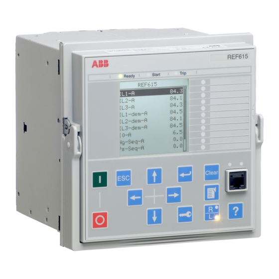
Page 24: Lhmi
Section 3 1MRS756708 A 615 series overview LHMI A070704 V2 EN Figure 1: LHMI The LHMI of the IED contains the following elements: • Display • Buttons • LED indicators • Communication port The LHMI is used for setting, monitoring and controlling. 3.2.1 The LHMI includes a graphical LCD that supports two character sizes. - Page 25 Section 3 1MRS756708 A 615 series overview Character size Rows in view Characters on row Small, mono-spaced (6x12 5 rows pixels) 10 rows with large screen Large, variable width (13x14 4 rows min 8 pixels) 8 rows with large screen The display view is divided into four basic areas: A070705 V2 EN Figure 2:...
-
Page 26: Leds
Section 3 1MRS756708 A 615 series overview The display is updated either cyclically or based on changes in the source data such as parameters or events. 3.2.2 LEDs The LHMI includes three protection indicators above the display: Ready, Start and Trip. - Page 27 Section 3 1MRS756708 A 615 series overview 11 Right 12 Key 13 Remote/Local 14 Menu 15 Help 16 Communication port Object control If the control position of the IED is set to local with the R/L button, the IED can be controlled using the object control buttons.
- Page 28 Section 3 1MRS756708 A 615 series overview Table 5: Navigation push-buttons Name Description • Leaving setting mode without saving the values. • Cancelling certain actions. • Adjusting the display contrast in combination with • Changing the language in combination with •...
-
Page 29: Lhmi Functionality
Section 3 1MRS756708 A 615 series overview 3.2.4 LHMI functionality 3.2.4.1 Protection and alarm indication Protection indicators Protection indicator LEDs are Ready, Start and Trip. Table 7: Ready LED LED state Description Auxiliary supply voltage is disconnected. Normal operation. Flashing Internal fault has occurred or the IED is in test mode. -
Page 30: Parameter Management
Section 3 1MRS756708 A 615 series overview Table 10: Alarm indications LED state Description Normal operation. All alarms are OFF. • Non-latched mode: alarm is still on. • Latched mode: alarm is still on or it is off but has not been acknowledged. -
Page 31: Whmi
Section 3 1MRS756708 A 615 series overview When a computer is connected to the IED, the IED's DHCP server for the front interface assigns an IP address to the computer. The fixed IP address for the front port is 192.168.0.254. WHMI The WHMI enables the user to access the IED via a web browser. -
Page 32: Command Buttons
Section 3 1MRS756708 A 615 series overview A070754 V3 EN Figure 5: Example view of the WHMI The WHMI can be accessed: • Locally by connecting your laptop to the IED via the front communication port. • Remotely over LAN/WAN. 3.3.1 Command buttons Command buttons can be used to edit parameters and control information via the... -
Page 33: Authorization
Section 3 1MRS756708 A 615 series overview Name Description Rejecting changes. Showing context sensitive help messages. Clearing events. Triggering the disturbance recorder manually. Saving values to CSV file format. Freezing the values so that updates are not displayed. Receiving continuous updates to the monitoring view. Deleting the disturbance record. -
Page 34: Communication
Section 3 1MRS756708 A 615 series overview Table 12: Predefined user categories Username User rights VIEWER Read only access OPERATOR • Selecting remote or local state with (only locally) • Changing setting groups • Controlling • Clearing alarm and indication LEDs and textual indications ENGINEER •... -
Page 35: Pcm600 Configuration Tool
Section 3 1MRS756708 A 615 series overview optic LC connector (100BASE-FX). An optional serial interface is available for RS-232/RS-485 communication. PCM600 configuration tool Protection and Control IED Manager PCM600 offers all the necessary functionality to work throughout all stages of the IED life cycle: •... -
Page 36: Pcm600 And Ied Connectivity Package Version
PCM600 and IED connectivity package version Supported tools: • Protection and Control IED Manager PCM600 Ver. 2.0 SP2 or later • Depending on the product, either REF615 Connectivity Package Ver. 2.0 or RED615 Connectivity Package Ver. 1.0 • Parameter Setting Tool •... -
Page 37: Section 4 Using Hmi Locally Or Via Web Interface
Section 4 1MRS756708 A Using HMI locally or via web interface Section 4 Using HMI locally or via web interface Using LHMI You must be logged in and authorized to use the LHMI. Password authorization is disabled by default and can be enabled either via the LHMI or WHMI. To enable password authorization, select Main Menu/ Configuration/Authorization/Local override. -
Page 38: Logging Out
Section 4 1MRS756708 A Using HMI locally or via web interface A070890 V2 EN Figure 7: Entering password Press to confirm the login. • To cancel the procedure, press A070889 V2 EN Figure 8: Error message indicating wrong password The current user level is shown on the LCD's upper right corner in the icon area. -
Page 39: Turning Display Backlight On
Section 4 1MRS756708 A Using HMI locally or via web interface A070837 V3 EN Figure 9: Logging out • To cancel logout, press 4.1.3 Turning display backlight on The display backlight is normally off. It turns on during the display test at power up. •... -
Page 40: Identifying The Device
Section 4 1MRS756708 A Using HMI locally or via web interface The control position cannot be simultaneously local and remote, but it can be disabled when neither of the positions is active. You must be logged in and authorized to control the IED. 4.1.5 Identifying the device The IED information includes detailed information about the device, such as revision... -
Page 41: Adjusting Display Contrast
Section 4 1MRS756708 A Using HMI locally or via web interface A071160 V2 EN Figure 11: IED information 4.1.6 Adjusting display contrast Adjust the display contrast anywhere in the menu structure to obtain optimal readability. • To increase the contrast, press simultaneously •... -
Page 42: Changing Display Symbols
Section 4 1MRS756708 A Using HMI locally or via web interface A071010 V2 EN Figure 12: Changing the LHMI language To change the language using a shortcut, press simultaneously. 4.1.8 Changing display symbols To switch between the display symbols IEC 61850, IEC 60617 and IEC-ANSI: Select Main Menu/Configuration/HMI/FB naming convention and press Change the display symbols with Press... -
Page 43: Menu Structure
Section 4 1MRS756708 A Using HMI locally or via web interface 4.1.9.1 Menu structure The Main menu contains main groups which are divided further into more detailed submenus. • Events • Measurements • Disturbance records • Settings • Configuration • Monitoring •... -
Page 44: Changing The Default View
Section 4 1MRS756708 A Using HMI locally or via web interface 4.1.9.3 Changing the default view The default view of the display is Measurements unless set otherwise. Select Main menu/Configuration/HMI/Default view and press Change the default view with Press to confirm the selection. 4.1.10 Browsing setting values Select Main Menu/Settings/Settings and press... -
Page 45: Editing Numerical Values
Section 4 1MRS756708 A Using HMI locally or via web interface 4.1.11.1 Editing numerical values Select Main menu/Settings and then a setting. When you start editing numerical values, the last digit is active. • When the symbol in front of the value is ↑, you can only increase the active value. -
Page 46: Editing String Values
Section 4 1MRS756708 A Using HMI locally or via web interface A070756 V2 EN Figure 17: Arrow symbol is active, the value is set to the maximum After pressing , the previous value can be restored by pressing once, and vice versa. -
Page 47: Committing Settings
Section 4 1MRS756708 A Using HMI locally or via web interface One press changes the enumerated value by one step in the parameter specific order. 4.1.12 Committing settings Editable values are stored either in RAM or in non-volatile flash memory. Values stored in flash memory are in effect also after reboot. -
Page 48: Clearing And Acknowledging
Section 4 1MRS756708 A Using HMI locally or via web interface 4.1.13 Clearing and acknowledging The Clear button is used to reset, acknowledge or clear all messages and indications, including LEDs and latched outputs as well as registers and recordings. Press the Clear button to activate a selection menu, where you can choose which clearance or reset function you want to make. -
Page 49: Using Whmi
Section 4 1MRS756708 A Using HMI locally or via web interface Using WHMI WHMI is disabled by default. You must be logged in and authorized to use the WHMI. To enable the WHMI, select Main menu/Configuration/HMI/Web HMI mode via the LHMI. Reboot the IED for the change to take effect. -
Page 50: Identifying The Device
Section 4 1MRS756708 A Using HMI locally or via web interface A070924 V3 EN Figure 22: WHMI logout 4.2.3 Identifying the device The IED information includes detailed information about the device, such as revision and serial number. Click Information in the WHMI menu structure. Click a submenu to see the data. -
Page 51: Navigating In The Menu
Section 4 1MRS756708 A Using HMI locally or via web interface A070925 V3 EN Figure 23: Device information 4.2.4 Navigating in the menu The menu tree structure on the WHMI is identical to the one on the LHMI. Use the menu bar to access different views. -
Page 52: Menu Structure
Section 4 1MRS756708 A Using HMI locally or via web interface A070945 V3 EN Figure 24: Navigating in the WHMI menus 4.2.4.1 Menu structure The Main menu contains main groups which are divided further into more detailed submenus. • Events •... - Page 53 Section 4 1MRS756708 A Using HMI locally or via web interface A070963 V3 EN Figure 25: Show all parameters Click Print to print out all parameters on paper. 615 series Operation Manual...
-
Page 54: Editing Values
Section 4 1MRS756708 A Using HMI locally or via web interface A071008 V3 EN Figure 26: All parameters listed Click Save to save all parameters in CSV file format. 4.2.6 Editing values Click the menu in the WHMI tree. Click the submenu to see function blocks. Click a function block to see the setting values. - Page 55 Section 4 1MRS756708 A Using HMI locally or via web interface A070929 V3 EN Figure 27: Enable writing to edit a value The selected setting group is shown in the Setting Group drop-down box. The active setting group is indicated with an asterisk *. Edit the value.
-
Page 56: Committing Settings
Section 4 1MRS756708 A Using HMI locally or via web interface A070934 V2 EN Figure 29: Warning indicating that the entered value is incorrect • If writing values fails, a warning dialog box is displayed. GUID-E10EE091-CFB9-4278-9FA4-7340C26F5814 V1 EN Figure 30: Warning indicating that the values were not written to the If you accidentally click Enable Write, click Disable Write. - Page 57 Section 4 1MRS756708 A Using HMI locally or via web interface A070931 V3 EN Figure 31: Writing values to IED The values are not stored to the flash memory. Click Commit to write the values to the flash memory. • Click Reject to cancel saving settings.
-
Page 58: Clearing And Acknowledging
Section 4 1MRS756708 A Using HMI locally or via web interface Committing values will take a few seconds. If you only write values to the IED and then reboot, the old values will resume in the IED as active values and the new values are lost. 4.2.8 Clearing and acknowledging Reset, acknowledge or clear all messages and indications, including LEDs and latched... -
Page 59: Selecting Alarm View
Section 4 1MRS756708 A Using HMI locally or via web interface A070936 V3 EN Figure 34: Clearing indications and LEDs 4.2.9 Selecting alarm view Alarm view shows the status of alarm LEDs. These are the same LEDs that are located on the upper right side of the LHMI panel. -
Page 60: Selecting Event View
Section 4 1MRS756708 A Using HMI locally or via web interface A070946 V3 EN Figure 35: Monitoring alarms 4.2.10 Selecting event view The event view contains a list of events produced by the application configuration. Click Events in the menu bar. 615 series Operation Manual... -
Page 61: Selecting The Disturbance Record View
Section 4 1MRS756708 A Using HMI locally or via web interface A070947 V3 EN Figure 36: Monitoring events Click Save to save the events in CSV file format. The CSV file can be opened with a spreadsheet program such as OpenOffice.org Calc or Microsoft Excel. -
Page 62: Uploading Disturbance Records
Section 4 1MRS756708 A Using HMI locally or via web interface GUID-2B46A09D-730E-45D3-BE30-20546BB6F8AD V1 EN 4.2.11.1 Uploading disturbance records Click Disturbance records on the menu bar. To upload a disturbance record, click the icons in the CFG and DAT columns of the record. 615 series Operation Manual... -
Page 63: Triggering The Disturbance Recorder Manually
Section 4 1MRS756708 A Using HMI locally or via web interface GUID-0280828D-0DFF-4C83-90A0-D8E57E17E51A V1 EN Save both the files in the same folder on your computer, and open the disturbance record files with a suitable program. 4.2.11.2 Triggering the disturbance recorder manually Click Disturbance records on the menu bar. -
Page 64: Deleting Disturbance Records
Section 4 1MRS756708 A Using HMI locally or via web interface GUID-4F5661CB-2317-4F4C-9DA2-BFADFA71BA3E V1 EN Figure 37: Manual triggering 4.2.11.3 Deleting disturbance records Click Disturbance records on the menu bar. Delete records. • Click Delete all to delete all records. • Select one or more recordings and click Delete to delete selected records. -
Page 65: Selecting Phasor Diagrams
Section 4 1MRS756708 A Using HMI locally or via web interface GUID-E109C24F-8CC9-4074-A175-DA4820BA7913 V1 EN Figure 38: Deleting disturbance records Click OK to confirm or Cancel to cancel the deletion. 4.2.12 Selecting phasor diagrams Click Phasor diagrams in the menu bar. 615 series Operation Manual... - Page 66 Section 4 1MRS756708 A Using HMI locally or via web interface A070948 V3 EN Figure 39: Monitoring phasors Toggle the diagram visibility by selecting it from the drop-down menu. 615 series Operation Manual...
- Page 67 Section 4 1MRS756708 A Using HMI locally or via web interface GUID-5F3C9CC8-1AE8-4235-836F-AC93E1E73708 V2 EN Figure 40: Toggling the diagram visibility Visible diagrams are indicated with an asterisk *. Change the size of the diagram by changing the zoom value. 615 series Operation Manual...
- Page 68 Section 4 1MRS756708 A Using HMI locally or via web interface GUID-690A11A9-FEC4-4558-A68F-16FBAC500E3B V2 EN Figure 41: Zooming the diagram Click Freeze to stop updating the phasor diagram. No updates are displayed in the diagram. 615 series Operation Manual...
-
Page 69: Selecting Disturbance Records
Section 4 1MRS756708 A Using HMI locally or via web interface A071226 V3 EN Figure 42: The arrow extends outside the circle if the current value is too high Install an SVG plugin to view the phasor diagrams. 4.2.13 Selecting disturbance records Click Disturbance records in the menu bar. - Page 70 Section 4 1MRS756708 A Using HMI locally or via web interface A070927 V3 EN Figure 43: Clicking the help button To close the help dialog box, click OK. 615 series Operation Manual...
-
Page 71: Section 5 Ied Operation
Section 5 1MRS756708 A IED operation Section 5 IED operation Normal operation The basic operation procedures in normal IED use situation are: • Monitoring measured values • Checking object states • Checking function setting parameters • Checking events and alarms All basic operations can be performed via the LHMI, WHMI or with PCM600. -
Page 72: Disturbance Recording Triggering
Section 5 1MRS756708 A IED operation Document the disturbance before clearing the information from the IED. Only authorized and skilled personnel should analyze possible errors and decide on further actions. Otherwise, stored disturbance data can be lost. 5.2.1 Disturbance recording triggering Disturbance recordings are normally triggered by IED applications when they detect fault events. -
Page 73: Ied Parametrization
Section 5 1MRS756708 A IED operation Only authorized and skilled personnel should analyze the errors and decide on further actions. The IED records: • IED status data • Events • System registrations Document all the recorded data from the IED before you reset the tripping and IED lockout functions. -
Page 74: Ied Settings For Different Operating Conditions
Section 5 1MRS756708 A IED operation 5.3.2 IED settings for different operating conditions IED settings can be designed for various operation conditions by defining different setting values to different setting groups. The active setting group can be changed by the IED application or manually via the LHMI. 615 series Operation Manual... -
Page 75: Section 6 Operating Procedures
Section 6 1MRS756708 A Operating procedures Section 6 Operating procedures Monitoring 6.1.1 Indications The operation of the IED can be monitored via three different indications on the LHMI. • Three indicator LEDs with fixed functionality: Ready, Start and Trip • 11 programmable alarm LEDs •... -
Page 76: Monitoring An Internal Ied Fault
Section 6 1MRS756708 A Operating procedures 6.1.1.2 Monitoring an internal IED fault The flashing green LED indicates an internal IED fault. Internal IED fault messages are shown in a dialog box. A071144 V2 EN Figure 45: Fault indication Select Main menu/Monitoring/IED status/Self-supervision to monitor the latest fault indication. -
Page 77: Using Lhmi For Monitoring
Section 6 1MRS756708 A Operating procedures Table 14: Measured values Indicator Description IL1-A Current measured on phase L1 IL2-A Current measured on phase L2 IL3-A Current measured on phase L3 Measured earth-fault current Measured residual voltage U12-kV Measured phase-to-phase voltage U12 U23-kV Measured phase-to-phase voltage U23 U31-kV... -
Page 78: Creating Disturbance Recordings
Section 6 1MRS756708 A Operating procedures 6.1.3.1 Creating disturbance recordings Normally disturbance recordings are triggered by the IED applications but the recording can also be triggered manually. Select Main menu/Disturbance records. Select Trig recording with Press , change the value with and press again. -
Page 79: Controlling And Uploading Disturbance Recorder Data
Section 6 1MRS756708 A Operating procedures A070863 V2 EN Figure 47: Monitoring disturbance recorder via the LHMI 6.1.3.3 Controlling and uploading disturbance recorder data Disturbance recorder data can be controlled and read with PCM600. It can also be uploaded via WHMI. For more information, see PCM600 documentation. -
Page 80: Monitoring Events
Section 6 1MRS756708 A Operating procedures 6.1.3.5 Monitoring events Event view contains a list of events produced by the application configuration. Each event takes one view area. The header area shows the currently viewed event index and the total amount of the events. The most recent event is always first. Select Main Menu/Events. -
Page 81: Controlling
Section 6 1MRS756708 A Operating procedures Controlling 6.2.1 Controlling circuit breakers and disconnectors The primary equipment can be controlled via the LHMI with the Open and Close buttons when the IED is set to local control mode and you are authorized to access control operations. -
Page 82: Resetting Ied
Section 6 1MRS756708 A Operating procedures The time between selecting the object and giving a control command is restricted by an adjustable time-out. When an object is selected, the control command has to be given within this time. Resetting IED 6.3.1 Clearing and acknowledging via LHMI You can reset, acknowledge or clear all messages and indications, including LEDs... -
Page 83: Changing Ied Functionality
Section 6 1MRS756708 A Operating procedures Use the button as a shortcut for clearing. The first three-second press clears the indications. The second three-second press clears the alarm LEDs. If new indications have appeared between the first and the second press, they are cleared first. Changing IED functionality 6.4.1 Defining setting group... -
Page 84: Copying A Setting Group
Section 6 1MRS756708 A Operating procedures A071152 V2 EN Figure 54: Selecting active setting group Commit the settings. Remember to document the changes you make. 6.4.1.2 Copying a setting group Select Main menu/Copy setting group and press Select the source and the destination with Set the group numbers with Press to confirm or... -
Page 85: Browsing And Editing Setting Group Values
Section 6 1MRS756708 A Operating procedures A070858 V2 EN Figure 55: Selecting a setting group 6.4.1.4 Browsing and editing setting group values Select Main Menu/Settings/Settings and press Select the setting group to be viewed with and press to confirm the selection. A071166 V2 EN Figure 56: Selecting setting group... - Page 86 Section 6 1MRS756708 A Operating procedures A070899 V3 EN Figure 57: Setting group parameter To select a setting group value, press and to edit the value press A071168 V3 EN Figure 58: Selecting setting group value Only values within the selected setting group can be changed. Press to change the value and to confirm the selection.
-
Page 87: Activating Leds
Section 6 1MRS756708 A Operating procedures 6.4.2 Activating LEDs Select Main Menu/Configuration/Alarm LEDs and press Select an Alarm LED with Press to confirm the selection and to change the Alarm LED mode. Press to change the value and to confirm the selection. For more information, see PCM600 documentation. -
Page 89: Section 7 Troubleshooting
Inspect the IED visually • Inspect the IED visually to find the physical error causes. • If you can find some obvious physical damage, contact ABB for repair or replacement actions. Check whether the error is external or internal. •... -
Page 90: Checking The Time Synchronization
Section 7 1MRS756708 A Troubleshooting Table 15: Communication LEDs Communication ok Uplink Steady green light Communication Flashing yellow light 7.1.3.2 Checking the time synchronization • Check the time synchronization via LHMI in Main Menu/Monitoring/IED status/Time synchronization. 7.1.4 Running the display test A short display test is always run, when auxiliary voltage is connected to the IED. - Page 91 Section 7 1MRS756708 A Troubleshooting A071144 V2 EN Figure 60: Fault indication Table 16: Internal fault indications and codes Fault indication Fault code Additional information Internal Fault An internal system error has occurred. System error Internal Fault A file system error has occurred. File system error Internal Fault Internal fault test activated manually by the...
-
Page 92: Warnings
Section 7 1MRS756708 A Troubleshooting Fault indication Fault code Additional information Internal Fault Card in slot X130 is wrong type, is missing Conf. error,X130 or does not belong to the original composition. Internal Fault Card in slot X000 is faulty. Card error,X000 Internal Fault Card in slot X100 is faulty. - Page 93 Section 7 1MRS756708 A Troubleshooting A071222 V2 EN Figure 61: Warning Table 17: Warning indications and codes Warning indication Warning code Additional information Warning A watchdog reset has occurred. Watchdog reset Warning The auxiliary supply voltage has dropped Power down det. too low.
-
Page 94: Led And Display Messages
Section 7 1MRS756708 A Troubleshooting Warning indication Warning code Additional information Warning A continuous light has been detected on ARC1 cont. light the ARC light input 1. Warning A continuous light has been detected on ARC2 cont. light the ARC light input 2. Warning A continuous light has been detected on ARC3 cont. -
Page 95: Identifying Ied Application Problems
In case of permanent faults, the measurement chain shall be checked to remove the origin of the faulty measurement data. In case of persistent faults originating from IED's internal faults, contact ABB for repair or replacement actions. 615 series Operation Manual... -
Page 97: Section 8 Commissioning
Section 8 1MRS756708 A Commissioning Section 8 Commissioning Commissioning checklist Familiarize yourself with the IED and its functionality before you start the commissioning work. • Ensure that you have all the needed station drawings such as single line and wiring diagrams. •... -
Page 98: Checking Ct Circuits
Section 8 1MRS756708 A Commissioning 8.2.2 Checking CT circuits The CTs must be connected in accordance with the terminal diagram provided with the IED, both with regards to phases and polarity. The following tests are recommended for every primary CT or CT core connected to the IED: •... -
Page 99: Checking Binary Input And Output Circuits
Section 8 1MRS756708 A Commissioning Test the circuitry. The following tests are recommended: • Polarity check • VT circuit voltage measurement (primary injection test) • Earthing check • Phase relationship • Insulation resistance check The polarity check verifies the integrity of circuits and the phase relationships. The polarity should be measured as close as possible to the IED so ensure that most of the wiring is also checked. -
Page 100: Using Pcm600
Section 8 1MRS756708 A Commissioning • Numbers 0-1 • Letters a-z, A-Z • Space • Special characters !"#%&'()*+´-./:;<=>?@[\]^_`{|}~ User authorization is disabled by default and can be enabled either via the LHMI or WHMI Main Menu/Configuration/ Authorization. Table 18: Predefined user categories Username LHMI WHMI password User rights... -
Page 101: Communication Options
Section 8 1MRS756708 A Commissioning Set up or get the IP addresses of the IEDs. Set up the PC for a direct link or connect the PC or workstation to the network. Configure the IED IP addresses in the PCM600 project for each IED. The addresses are used for communication by the OPC interface of PCM600. - Page 102 Section 8 1MRS756708 A Commissioning To open Network Connections, click Start, point to Settings, click Control Panel, and then double-click Network Connections. Double-click the connection that you want to configure, and then click Properties. Select the TCP/IP protocol from the list of configured components using this connection and click Properties.
- Page 103 Section 8 1MRS756708 A Commissioning A071224 V1 EN Figure 63: Obtaining IP address automatically Close all open windows by clicking OK and start PCM600. Administrator rights are requested to change the configuration as described above. Setting rear communication To set up a standard PC with MicroSoft Windows operating system for rear communication: To open Network Connections, click Start, point to Settings, click Control Panel, and then double-click Network Connections.
- Page 104 Section 8 1MRS756708 A Commissioning A071162 V1 EN Figure 64: Selecting TCP/IP protocol Choose Use the following IP address. Enter an IP address and a subnet mask. Make sure that the IP address is unique, that is not used by any other IED on the network.
- Page 105 Section 8 1MRS756708 A Commissioning A071164 V1 EN Figure 65: Setting IP address and subnet mask Close all open windows by clicking OK and start PCM600. Administrator rights are requested to change the configuration as described above. Setting IED's IP address in PCM600 In PCM600 the IED's IP address can be defined either via the first window of the wizard by including a new IED in the project or by entering the IED's IP address in the Object Properties window.
-
Page 106: Setting Ied And Communication
Section 8 1MRS756708 A Commissioning Setting IED and communication 8.5.1 Communication settings The IED is provided with an RJ-45 connector on the LHMI. The connector is mainly used for configuration and setting purposes. The fixed IP address for the front port is 192.168.0.254. -
Page 107: Serial Link Diagnostics And Monitoring
Section 8 1MRS756708 A Commissioning COM parameter Values Hardware options Serial mode 0 = RS485 2wire For galvanic modes. RS-type depends on the communication card used. 1 = RS485 4wire Note that this setting parameter is Fiber mode is set to No relevant only if 2 = RS232 no handshake Fiber . - Page 108 Section 8 1MRS756708 A Commissioning serial link driver. Diagnostic counters and monitoring values are found via the LHMI in Monitoring/Communication/COMn (n= 1,2,…). Depending on the communication protocol, the serial driver software receives single characters or complete protocol frames, based on the frame start/stop characters or on timing.
- Page 109 Section 8 1MRS756708 A Commissioning Table 21: Basic diagnostic counters Counter Function Characters received Counts all incoming non-erroneous characters. This counter operates regardless of if the serial driver is set to detect a whole protocol link frame or just separate characters. Frames received Counts all protocol specific non-erroneous frames received.
-
Page 110: Defining Ethernet Port Settings
Section 8 1MRS756708 A Commissioning Table 23: Link status Parameter Function Link status Link status in write direction: By writing 1 to the parameter the diagnostic counters are reset to 0. Link status in monitoring direction: If the driver is in use by any communication protocol, the monitoring value shows 1. -
Page 111: Setting Lhmi
Section 8 1MRS756708 A Commissioning 8.5.2 Setting LHMI 8.5.2.1 Changing LHMI language Select Main Menu/Language and press Change the language with Press to confirm the selection. Commit the changes. A071010 V2 EN Figure 66: Changing the LHMI language To change the language using a shortcut, press simultaneously. -
Page 112: Changing The Default View
Section 8 1MRS756708 A Commissioning Select Main Menu/Configuration/HMI/FB naming convention and press Change the display symbols with Press to confirm the selection. The IED has to be rebooted if the WHMI display symbols are changed. With the LHMI, the change takes effect immediately. 8.5.2.4 Changing the default view The default view of the display is Measurements unless set otherwise. -
Page 113: Setting Ied Parameters
Section 8 1MRS756708 A Commissioning Table 24: DST change on Sunday Day of the DST shift DST on/off date First Sunday of the month Second Sunday of the month Third Sunday of the month Fourth Sunday of the month Last Sunday, if the month has 30 days Last Sunday, if the month has 31 days For example, if the DST is observed from the last Sunday in March to the last Sunday in October and the time shift occurs at 01:00 UTC, the setting parameters... - Page 114 Section 8 1MRS756708 A Commissioning A070858 V2 EN Figure 67: Selecting a setting group Browsing and editing setting group values Select Main Menu/Settings/Settings and press Select the setting group to be viewed with and press to confirm the selection. A071166 V2 EN Figure 68: Selecting setting group To browse the settings, scroll the list with...
- Page 115 Section 8 1MRS756708 A Commissioning A070899 V3 EN Figure 69: Setting group parameter To select a setting group value, press and to edit the value press A071168 V3 EN Figure 70: Selecting setting group value Only values within the selected setting group can be changed. Press to change the value and to confirm the selection.
-
Page 116: Ied Parametrization
Section 8 1MRS756708 A Commissioning Activating a setting group IED settings are planned in advance for different operation conditions by calculating setting values to different setting groups. The active setting group can be changed by the IED application or manually from the menu. Select Main Menu/Settings/Setting group/Active group and press A071150 V2 EN Figure 72:... -
Page 117: Defining Disturbance Recorder Channel Settings
Section 8 1MRS756708 A Commissioning Setting parameters need to be calculated according to the electrical network conditions and the electrical characteristics of the protected equipment. The IED's settings need to be verified before the IED is connected to a system. Document all changes to parameter settings. -
Page 118: Testing Digital I/O Interface
Section 8 1MRS756708 A Commissioning The Ready LED also flashes if the IED detects a diagnostic failure. Check the test mode setting and the IED's IRF alarm contact status to find the reason for the failure. Select Main menu/Tests/IED test/Test mode and press A071154 V2 EN Figure 74: Entering test mode... -
Page 119: Testing Functions
Section 8 1MRS756708 A Commissioning 8.6.3 Testing functions To activate or deactivate an output signal for protection or other function: Select Main Menu/Tests/Function tests/Current protection/PHLPTOC and press Select the output signal to be activated or deactivated with and press To deactivate all output signals for the function, select Reset with and press 8.6.4 Selecting internal fault test... -
Page 120: Abb Product Data Registration
1MRS756708 A Commissioning ABB Product Data Registration The ABB Product Data Registration feature traces composition changes related to the IED's SW or HW. After a composition change, an LCT indication is seen on the LHMI at the IED start- up. At this point, PCM600 should be connected to the IED as it reads the changed data from the IED. -
Page 121: Section 9 Glossary
Section 9 Glossary Section 9 Glossary 100BASE-FX A physical media defined in the IEEE 802.3 Ethernet standard for local area networks (LANs). 100BASE-FX uses fibre-optic cabling. 100BASE-TX A physical media defined in the IEEE 802.3 Ethernet standard for local area networks (LANs). 100BASE-TX uses twisted-pair cabling category 5 or higher with RJ-45 connectors. - Page 122 Section 9 Glossary Firmware System software or hardware that has been written and stored in a device's memory that controls the device. FPGA Field Programmable Gate Array GOOSE Generic Object Oriented Substation Event Human-machine interface Hardware International Electrotechnical Commission IEC 60870-5-103 Communication standard for protective equipment.
- Page 123 Section 9 Glossary PCM600 Protection and Control IED Manager Parameter Setting Tool in PCM600 Remote/Local Random access memory RJ-45 Galvanic connector type. RoHS Restriction of the use of certain Hazardous Substances in electrical and electronic equipment. Read-only memory RS-232 Serial interface standard. RS-485 Serial link according to EIA standard RS485.
- Page 126 ABB Oy Distribution Automation P.O. Box 699 FI-65101 VAASA, Finland Phone +358 10 22 11 +358 10 22 41094 www.abb.com/substationautomation...
Need help?
Do you have a question about the REF615 and is the answer not in the manual?
Questions and answers