ABB RED615 Applications Manual
Line differential protection and control
Hide thumbs
Also See for RED615:
- Technical manual (896 pages) ,
- Operation manual (116 pages) ,
- Applications manual (92 pages)

Related Manuals for ABB RED615


Summary of Contents for ABB RED615
- Page 1 — RELION® 615 SERIES Line Differential Protection and Control RED615 Application Manual...
- Page 3 Document ID: 1MRS758127 Issued: 2019-04-30 Revision: C Product version: 5.0 FP1 © Copyright 2019 ABB. All rights reserved...
- Page 4 Copyright This document and parts thereof must not be reproduced or copied without written permission from ABB, and the contents thereof must not be imparted to a third party, nor used for any unauthorized purpose. The software or hardware described in this document is furnished under a license and may be used, copied, or disclosed only in accordance with the terms of such license.
- Page 5 In case any errors are detected, the reader is kindly requested to notify the manufacturer. Other than under explicit contractual commitments, in no event shall ABB be responsible or liable for any loss or damage resulting from the use of this manual or the application of the equipment.
- Page 6 Conformity This product complies with the directive of the Council of the European Communities on the approximation of the laws of the Member States relating to electromagnetic compatibility (EMC Directive 2014/30/EU) and concerning electrical equipment for use within specified voltage limits (Low-voltage directive 2014/35/EU). This conformity is the result of tests conducted by the third party testing laboratory Intertek in accordance with the product standard EN 60255-26 for the EMC directive, and with the product standards EN 60255-1 and EN 60255-27 for the low voltage directive.
-
Page 7: Table Of Contents
Self-healing Ethernet ring............24 Ethernet redundancy..............25 Process bus.................27 Secure communication..............29 Protection communication and supervision......... 29 Section 3 RED615 standard configurations........31 Standard configurations..............31 Addition of control functions for primary devices and the use of binary inputs and outputs............34 Connection diagrams................35 Standard configuration C..............37... - Page 8 93 Non-directional overcurrent protection........94 Example for non-directional overcurrent protection....95 Section 5 Protection relay's physical connections......97 Inputs....................97 Energizing inputs................. 97 Phase currents............... 97 Residual current..............97 Phase voltages...............97 Residual voltage..............97 Auxiliary supply voltage input............98 Binary inputs................98 RED615 Application Manual...
- Page 9 Table of contents RTD/mA inputs................100 Outputs................... 100 Outputs for tripping and controlling..........100 Outputs for signalling..............101 IRF.....................102 Protection communication options..........102 Section 6 Glossary............... 105 RED615 Application Manual...
-
Page 11: Section 1 Introduction
This manual addresses the protection and control engineer responsible for planning, pre-engineering and engineering. The protection and control engineer must be experienced in electrical power engineering and have knowledge of related technology, such as protection schemes and principles. RED615 Application Manual... -
Page 12: Product Documentation
1.3.2 Document revision history Document revision/date Product version History A/2014-05-14 First release B/2014-09-12 4.1.1 Content updated to correspond to the product version C/2019-04-30 5.0 FP1 Content updated Download the latest documents from the ABB Web site http://www.abb.com/substationautomation. RED615 Application Manual... -
Page 13: Related Documentation
Although warning hazards are related to personal injury, it is necessary to understand that under certain operational conditions, operation of damaged equipment may result in degraded process performance leading to personal injury or death. Therefore, comply fully with all warning and caution notices. RED615 Application Manual... -
Page 14: Document Conventions
When the function starts, the START output is set to TRUE. • This document assumes that the parameter setting visibility is "Advanced". 1.4.3 Functions, codes and symbols Table 1: RED615 functions, codes and symbols Function IEC 61850 IEC 60617 IEC-ANSI Protection... - Page 15 3Ith>T/G/C (1) 49T/G/C (1) protection, two time constants Binary signal transfer BSTGGIO1 BST (1) BST (1) Circuit breaker failure protection CCBRBRF1 3I>/Io>BF (1) 51BF/51NBF (1) Three-phase inrush detector INRPHAR1 3I2f> (1) 68 (1) Table continues on next page RED615 Application Manual...
- Page 16 I <-> O DC (3) I <-> O DC (3) Earthing switch indication ESSXSWI1 I <-> O ES (1) I <-> O ES (1) ESSXSWI2 I <-> O ES (2) I <-> O ES (2) Table continues on next page RED615 Application Manual...
- Page 17 TP (3) TP (3) TPGAPC4 TP (4) TP (4) Minimum pulse timer (2 pcs, second TPSGAPC1 TPS (1) TPS (1) resolution) Minimum pulse timer (2 pcs, minute TPMGAPC1 TPM (1) TPM (1) resolution) Table continues on next page RED615 Application Manual...
- Page 18 SPC (1) SPCGAPC2 SPC (2) SPC (2) Analog value scaling SCA4GAPC1 SCA4 (1) SCA4 (1) SCA4GAPC2 SCA4 (2) SCA4 (2) SCA4GAPC3 SCA4 (3) SCA4 (3) SCA4GAPC4 SCA4 (4) SCA4 (4) Integer value move MVI4GAPC1 MVI4 (1) MVI4 (1) RED615 Application Manual...
-
Page 19: Section 2 Red615 Overview
RED615 relays communicate between substations over a fiber ® optic link or a galvanic pilot wire connection. RED615 is a member of ABB’s Relion product family and part of its 615 protection and control product series. The 615 series relays are characterized by their compactness and withdrawable-unit design. -
Page 20: Product Version History
Additional timer, set-reset and analog value scaling functions 2.1.2 PCM600 and relay connectivity package version • Protection and Control IED Manager PCM600 2.9 Hotfix 1 or later • RED615 Connectivity Package Ver.5.1 or later • Parameter Setting • Signal Monitoring •... -
Page 21: Operation Functionality
Section 2 1MRS758127 C RED615 overview Download connectivity packages from the ABB Web site http://www.abb.com/substationautomation or directly with Update Manager in PCM600. Operation functionality 2.2.1 Optional functions • Autoreclosing • Modbus TCP/IP or RTU/ASCII • IEC 60870-5-103 • Admittance-based earth-fault protection (configuration D only) •... -
Page 22: Local Hmi
Section 2 1MRS758127 C RED615 overview Main Slot ID Content options Case X130 AI/BI module Only with configuration D: 3 phase voltage inputs (60...210 V) 1 residual voltage input (60...210 V) 4 binary inputs AI/RTD/mA module Only with configuration D: 3 phase voltage inputs (60...210 V) -
Page 23: Display
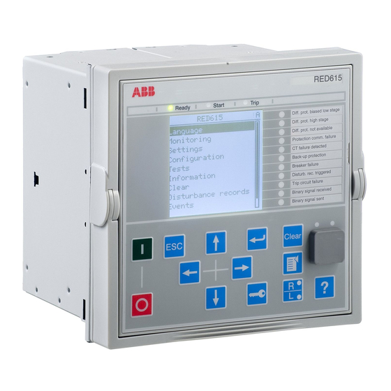
Section 2 1MRS758127 C RED615 overview REF615 Overcurrent Dir. earth-fault Voltage protection Phase unbalance Thermal overload Breaker failure Disturb. rec. Triggered CB condition monitoring Supervision Arc detected Autoreclose shot in progr. A070704 V4 EN Figure 2: Example of the LHMI 2.4.1... -
Page 24: Leds
Section 2 1MRS758127 C RED615 overview The display view is divided into four basic areas. A070705 V3 EN Figure 3: Display layout 1 Header 2 Icon 3 Content 4 Scroll bar (displayed when needed) 2.4.2 LEDs The LHMI includes three protection indicators above the display: Ready, Start and Trip. -
Page 25: Web Hmi
Section 2 1MRS758127 C RED615 overview A071176 V1 EN Figure 4: LHMI keypad with object control, navigation and command push buttons and RJ-45 communication port Web HMI The WHMI allows secure access to the protection relay via a Web browser. When the Secure Communication parameter in the protection relay is activated, the Web server is forced to take a secured (HTTPS) connection to WHMI using TLS encryption.The... -
Page 26: Authorization
Section 2 1MRS758127 C RED615 overview GUID-38AF6905-4903-4C61-B22C-8509D99398E0 V1 EN Figure 5: Example view of the WHMI The WHMI can be accessed locally and remotely. • Locally by connecting the laptop to the protection relay via the front communication port. •... -
Page 27: Audit Trail
Section 2 1MRS758127 C RED615 overview Table 6: Predefined user categories Username User rights VIEWER Read only access OPERATOR • Selecting remote or local state with (only locally) • Changing setting groups • Controlling • Clearing indications ENGINEER • Changing settings •... - Page 28 Section 2 1MRS758127 C RED615 overview Table 7: Audit trail events Audit trail event Description Configuration change Configuration files changed Firmware change Firmware changed Firmware change fail Firmware change failed Attached to retrofit test case Unit has been attached to retrofit case...
-
Page 29: Communication
Section 2 1MRS758127 C RED615 overview Table 8: Comparison of authority logging levels Audit trail event Authority logging level Configurati Setting Setting Settings None on change group group, edit control Configuration change ● ● ● ● ● Firmware change ●... -
Page 30: Self-Healing Ethernet Ring
Section 2 1MRS758127 C RED615 overview (so-called horizontal communication) using the IEC 61850-8-1 GOOSE profile, where the highest performance class with a total transmission time of 3 ms is supported. Furthermore, the protection relay supports sending and receiving of analog values using GOOSE messaging. -
Page 31: Ethernet Redundancy
HSR applies the PRP principle to rings and to the rings of rings to achieve cost- effective redundancy. Thus, each device incorporates a switch element that forwards frames from port to port. The HSR/PRP option is available for all 615 series protection relays. However, RED615 supports this option only over fiber optics. RED615 Application Manual... - Page 32 Section 2 1MRS758127 C RED615 overview IEC 62439-3:2012 cancels and replaces the first edition published in 2010. These standard versions are also referred to as IEC 62439-3 Edition 1 and IEC 62439-3 Edition 2. The protection relay supports IEC 62439-3:2012 and it is not compatible with IEC 62439-3:2010.
-
Page 33: Process Bus
Section 2 1MRS758127 C RED615 overview • Via an external redundancy box (RedBox) or a switch capable of connecting to PRP and normal networks • By connecting the node directly to LAN A or LAN B as SAN • By connecting the node to the protection relay's interlink port HSR applies the PRP principle of parallel operation to a single ring, treating the two directions as two virtual LANs. - Page 34 Section 2 1MRS758127 C RED615 overview UniGear Digital switchgear concept relies on the process bus together with current and voltage sensors. The process bus enables several advantages for the UniGear Digital like simplicity with reduced wiring, flexibility with data availability to all devices, improved diagnostics and longer maintenance cycles.
-
Page 35: Secure Communication
The process bus option is available for all 615 series protection relays equipped with phase voltage inputs. Another requirement is a communication card with IEEE 1588 v2 support (COM0031...COM0037). However, RED615 supports this option only with the communication card variant having fiber optic station bus ports. See the IEC 61850 engineering guide for detailed system requirements and configuration details. - Page 36 Section 2 1MRS758127 C RED615 overview Apart from the continued protection communication, the communication channel can also be used for binary signal transfer (BST) that is, transferring of user configurable binary information between the relays. There are a total of eight BST signals available for user definable purposes.
-
Page 37: Section 3 Red615 Standard Configurations
The relay is delivered from the factory with default connections described in the functional diagrams for binary inputs, binary outputs, function-to-function connections and alarm LEDs. Some of the supported functions in RED615 must be added with the Application Configuration tool to be available in the Signal Matrix tool and in the relay. - Page 38 Section 3 1MRS758127 C RED615 standard configurations Function IEC 61850 Admittance-based earth-fault protection EFPADM Wattmetric-based earth-fault protection WPWDE Transient/intermittent earth-fault protection INTRPTEF Harmonics-based earth-fault protection HAEFPTOC 1)2) 1)2) Non-directional (cross-country) earth-fault protection, using calculated Io EFHPTOC Negative-sequence overcurrent protection NSPTOC...
- Page 39 Section 3 1MRS758127 C RED615 standard configurations Function IEC 61850 Trip circuit supervision TCSSCBR Current circuit supervision CCSPVC Advanced current circuit supervision for line differential LNCTSRCTF Fuse failure supervision SEQSPVC1 Protection communication supervision PCSITPC1 Runtime counter for machines and devices...
-
Page 40: Addition Of Control Functions For Primary Devices And The Use Of Binary Inputs And Outputs
Section 3 1MRS758127 C RED615 standard configurations 3.1.1 Addition of control functions for primary devices and the use of binary inputs and outputs If extra control functions intended for controllable primary devices are added to the configuration, additional binary inputs and/or outputs are needed to complement the standard configuration. -
Page 41: Connection Diagrams
Section 3 1MRS758127 C RED615 standard configurations Connection diagrams RED615 X120 X100 BI 1 Positive Current Direction BI 2 BI 3 BI 4 Protection Core 1/5A 1/5A 1/5A 1/5A Earth Fault and CT Supervision Reference Current X110 BI 1 BI 2... - Page 42 Section 3 1MRS758127 C RED615 standard configurations RED615 X120 X100 BI 1 Positive Current Direction BI 2 BI 3 BI 4 1/5A 1/5A 1/5A 1/5A X130 BI 1 BI 2 TCS1 BI 3 BI 4 TCS2 60 - 210V U12B...
-
Page 43: Standard Configuration C
Section 3 1MRS758127 C RED615 standard configurations Standard configuration C 3.3.1 Applications The standard configuration for line current differential protection including non- directional earth-fault protection and autoreclosing is mainly intended for cable feeder applications in the distribution networks. The standard configuration for line current differential protection includes support for in-zone transformers. -
Page 44: Functions
Section 3 1MRS758127 C RED615 standard configurations 3.3.2 Functions RED615 LINE DIFFERENTIAL PROTECTION AND CONTROL RELAY STANDARD With in-zone power transformer support CONFIGURATION PROTECTION LOCAL HMI ALSO AVAILABLE - Binary Signal Transfer function (BST) 2× - Disturbance and fault recorder... - Page 45 Section 3 1MRS758127 C RED615 standard configurations Table 11: Default connections for analog inputs Analog input Description Connector pins Phase A current X120:7-8 Phase B current X120:9-10 Phase C current X120:11-12 Residual current X120:13-14 Table 12: Default connections for binary inputs...
-
Page 46: Default Disturbance Recorder Settings
Section 3 1MRS758127 C RED615 standard configurations Binary output Description Connector pins X110-SO4 X110:23-24 X130-SO1 X130:10-12 X130-SO2 X130:13-15 X130-SO3 X130:16-18 Table 14: Default connections for LEDs Description Line differential protection biased stage operate Line differential protection instantaneous stage operate Line differential protection is not available... - Page 47 Section 3 1MRS758127 C RED615 standard configurations Table 16: Default disturbance recorder binary channels Channel ID text Level trigger mode LNPLDF1 - start Positive or Rising LNPLDF1 - operate Positive or Rising PHIPTOC1 - start Positive or Rising PHHPTOC1 - start...
- Page 48 Section 3 1MRS758127 C RED615 standard configurations Channel ID text Level trigger mode X110-BI3 - gas pressure alarm Level trigger off X120-BI3 - CB open Level trigger off X120-BI2 - CB closed Level trigger off X120-BI1 - ext OC blocking...
-
Page 49: Functional Diagrams
Section 3 1MRS758127 C RED615 standard configurations 3.3.3 Functional diagrams The functional diagrams describe the default input, output, alarm LED and function- to-function connections. The default connections can be viewed and changed with PCM600 according to the application requirements. The analog channels have fixed connections to the different function blocks inside the protection relay’s standard configuration. - Page 50 Section 3 1MRS758127 C RED615 standard configurations LNPLDF1 BLOCK OPERATE LNPLDF1_OPERATE BLOCK_LS START CCSPVC1_FAIL LNPLDF1_START ENA_MULT_HS STR_LS_LOC REMOTE_CCSPVC_FAIL STR_LS_REM OPR_LS_LOC LNPLDF1_OPR_LS_LOC OPR_LS_REM LNPLDF1_OPR_LS_REM OPR_HS_LOC LNPLDF1_OPR_HS_LOC OPR_HS_REM LNPLDF1_OPR_HS_REM BLKD2H_LOC LNPLDF1_BLKD2H_LOC BLKD2H_REM REMOTE_FEEDER_READY LNPLDF1_BLKD2H_REM PRO_ACTIVE REMOTE_CB_OPEN LNPLDF1_PROT_ACTIVE LNPLDF1_OPR_LS_LOC LNPLDF_LS_OPERATE LNPLDF1_OPR_LS_REM LNPLDF1_PROT_ACTIVE LNPLDF1_PROT_NOT_ACTIVE...
- Page 51 Section 3 1MRS758127 C RED615 standard configurations PHIPTOC1_START UPSTREAM_OC_BLOCKING PHHPTOC1_START PHHPTOC2_START GUID-FFE28D0E-8985-4E5C-A14B-CB6DE0B30D72 V1 EN Figure 17: Upstream blocking logic Four stages are provided for non-directional earth-fault protection. According to the order code, the configuration can also include optional harmonics-based earth-fault protection HAEFPTOC1.
- Page 52 Section 3 1MRS758127 C RED615 standard configurations INRPHAR1 BLOCK BLK2H INRPHAR1_BLK2H GUID-7F2BFC97-5C00-40C0-ABBA-3FC501D58D5D V1 EN Figure 19: Inrush detector function Two negative-sequence overcurrent protection stages NSPTOC1 and NSPTOC2 are provided for phase unbalance protection. These functions are used to protect the feeder against phase unbalance.
- Page 53 Section 3 1MRS758127 C RED615 standard configurations T1PTTR1 BLK_OPR OPERATE T1PTTR1_OPERATE ENA_MULT START T1PTTR1_START TEMP_AMB ALARM T1PTTR1_ALARM BLK_CLOSE T1PTTR1_BLK_CLOSE T2PTTR1 BLOCK OPERATE T2PTTR1_OPERATE TEMP_AMB START T2PTTR1_START ALARM T2PTTR1_ALARM BLK_CLOSE T2PTTR1_BLK_CLOSE GUID-C71ADCD1-5E9F-47CF-AF75-D8CD007C423A V1 EN Figure 22: Thermal overcurrent protection function The negative-sequence overcurrent protection, phase discontinuity protection and earth-fault protection are all used as backup protection against line differential protection.
- Page 54 Section 3 1MRS758127 C RED615 standard configurations DARREC1 INIT_1 OPEN_CB LNPLDF_LS_OPERATE DARREC1_OPEN_CB INIT_2 CLOSE_CB PHIPTOC1_OPERATE DARREC1_CLOSE_CB INIT_3 CMD_WAIT PHHPTOC2_OPERATE INIT_4 INPRO PHHPTOC1_OPERATE DARREC1_INPRO INIT_5 LOCKED EFLPTOC1_OPERATE INIT_6 PROT_CRD EFHPTOC1_OPERATE DEL_INIT_2 UNSUC_RECL DARREC1_UNSUC_RECL DEL_INIT_3 AR_ON DEL_INIT_4 READY BLK_RECL_T ACTIVE BLK_RCLM_T BLK_THERM...
-
Page 55: Functional Diagrams For Disturbance Recorder
Section 3 1MRS758127 C RED615 standard configurations lockout and latching function, event generation and the trip signal duration setting. If the lockout operation mode is selected, binary input X120:BI4 can be assigned to RST_LKOUT input of both the trip logic to enable external reset with a push button. -
Page 56: Functional Diagrams For Condition Monitoring
Section 3 1MRS758127 C RED615 standard configurations RDRE1 TRIGGERED LNPLDF1_START DISTURB_RECORD_TRIGGERED LNPLDF1_OPERATE PHIPTOC1_START PHHPTOC1_START PHHPTOC2_START PHLPTOC1_START T1PTTR1_START PHIPTOC1_OPERATE T2PTTR1_START PHHPTOC1_OPERATE PDNSPTOC1_START PHHPTOC2_OPERATE NSPTOC1_START PHLPTOC1_OPERATE NSPTOC2_START EFHPTOC1_START EFIPTOC1_START EFLPTOC1_START EFLPTOC2_START CCBRBRF1_TRRET CCBRBRF1_TRBU LNPLDF_BLKD2H LNPLDF1_PROT_NOT_ACTIVE NSPTOC1_OPERATE NSPTOC2_OPERATE PDNSPTOC1_OPERATE T1PTTR1_ALARM T2PTTR1_ALARM T1PTTR1_OPERATE INRPHAR1_BLK2H... - Page 57 Section 3 1MRS758127 C RED615 standard configurations Set the parameters for SSCBR1 properly. SSCBR1 BLOCK TRV_T_OP_ALM SSCBR1_TRV_T_OP_ALM POSOPEN TRV_T_CL_ALM X120_BI3_CB_OPENED SSCBR1_TRV_T_CL_ALM POSCLOSE SPR_CHR_ALM X120_BI2_CB_CLOSED SSCBR1_SPR_CHR_ALM OPEN_CB_EXE OPR_ALM CB_OPEN_COMMAND SSCBR1_OPR_ALM CLOSE_CB_EXE OPR_LO CB_CLOSE_COMMAND SSCBR1_OPR_LO PRES_ALM_IN IPOW_ALM X110_BI3_GAS_PRESSURE_ALARM SSCBR1_IPOW_ALM PRES_LO_IN IPOW_LO SSCBR1_IPOW_LO...
- Page 58 Section 3 1MRS758127 C RED615 standard configurations TCSSCBR1 BLOCK ALARM TCSSCBR_BLOCKING TCSSCBR1_ALARM TCSSCBR2 BLOCK ALARM TCSSCBR_BLOCKING TCSSCBR2_ALARM TCSSCBR1_ALARM TCSSCBR_ALARM TCSSCBR2_ALARM GUID-521ECF9A-25C2-4582-8D40-1EA572E4C847 V1 EN Figure 32: Trip circuit supervision function TRPPTRC1_TRIP TCSSCBR_BLOCKING TRPPTRC2_TRIP X120_BI3_CB_OPENED GUID-36DBAACC-5D67-414F-89E1-DAB5F6411181 V1 EN Figure 33: Logic for blocking of trip circuit supervision Protection communication supervision PCSITPC1 is used in the configuration to block the operation of the line differential function.
-
Page 59: Functional Diagrams For Control And Interlocking
Section 3 1MRS758127 C RED615 standard configurations As a consequence of sending interlocking information to remote end, also receiving of same information locally is needed. Therefore, remote feeder ready, remote circuit breaker open and remote current transformer failure are connected to the binary signal transfer function outputs. - Page 60 Section 3 1MRS758127 C RED615 standard configurations If REMOTE_FEEDER_READY information is missing, for example, in case of protection communication not connected, it disables the breaker closing in the local protection relay. Any additional signals required by the application can be connected for opening and closing of circuit breaker.
- Page 61 Section 3 1MRS758127 C RED615 standard configurations REMOTE_FEEDER_READY CBXCBR1_ENA_CLOSE LOCAL_FEEDER_READY AND6 DCSXSWI1_OKPOS LOCAL_FEEDER_READY ESSXSWI1_OPENPOS X110_BI4_CB_SPRING_CHARGED TRPPTRC1_TRIP TRPPTRC2_TRIP X110_BI3_GAS_PRESSURE_ALARM GUID-BB477666-A6B7-43C1-AE6B-D20528F6EDFC V1 EN Figure 41: Circuit breaker 1 close enable logic Connect higher-priority conditions before enabling the circuit breaker. These conditions cannot be bypassed with bypass feature of the function.
-
Page 62: Functional Diagrams For Measurement Functions
Section 3 1MRS758127 C RED615 standard configurations CONTROL_LOCAL FALSE CBXBCR1_AU_OPEN CONTROL_REMOTE FALSE GUID-B2A3DFEB-8777-40F7-AA7B-39FD2EEF3F09 V1 EN Figure 44: External opening command for circuit breaker 1 3.3.3.5 Functional diagrams for measurement functions The phase current inputs to the protection relay are measured by the three-phase current measurement function CMMXU1. -
Page 63: Functional Diagrams For I/O And Alarm Leds
Section 3 1MRS758127 C RED615 standard configurations FLTRFRC1 BLOCK CB_CLRD GUID-557D77EF-39F9-4E45-B681-4214A621ABBF V2 EN Figure 48: Other measurement: Data monitoring LDPRLRC1 RSTMEM MEM_WARN MEM_ALARM GUID-86C0CEA1-CD8A-4D98-83DE-D9F56D43A917 V2 EN Figure 49: Other measurement: Load profile record 3.3.3.6 Functional diagrams for I/O and alarm LEDs X110_BI1_EXT_CCBRBRF_START X110 (BIO).X110-Input 1... - Page 64 Section 3 1MRS758127 C RED615 standard configurations X120_BI1_EXT_OC_BLOCKING X120 (AIM).X120-Input 1 X120_BI2_CB_CLOSED X120 (AIM).X120-Input 2 X120_BI3_CB_OPENED X120 (AIM).X120-Input 3 X120_BI4_RST_LOCKOUT X120 (AIM).X120-Input 4 GUID-C10DB2F8-2663-4CDC-B032-F425F58578D9 V1 EN Figure 51: Binary inputs - X120 terminal block UPSTREAM_OC_BLOCKING X110 (BIO).X110-SO1 BACKUP_PROT_OPERATE_PULSE X110 (BIO).X110-SO2 REMOTE_BINARY_TRANSFER X110 (BIO).X110-SO3...
- Page 65 Section 3 1MRS758127 C RED615 standard configurations LED1 ALARM LNPLDF_LS_OPERATE RESET LED2 ALARM LNPLDF_HS_OPERATE RESET LED3 ALARM LNPLDF1_PROT_NOT_ACTIVE RESET LED4 ALARM PCSITPC1_ALARM RESET LED5 ALARM DARREC1_INPRO RESET GUID-47DBECE3-D6D9-47CB-ACA7-A7D3B54613EA V2 EN RED615 Application Manual...
-
Page 66: Functional Diagrams For Other Timer Logics
Section 3 1MRS758127 C RED615 standard configurations LED6 ALARM BACKUP_PROT_OPERATE RESET T1PTTR1_ALARM T2PTTR1_ALARM LED7 ALARM CCBRBRF1_TRBU RESET LED8 ALARM DISTURB_RECORD_TRIGGERED RESET LED9 ALARM SSCBR1_ALARMS RESET CCSPVC1_ALARM TCSSCBR_ALARM LED10 ALARM BSTGGIO1_RECV_SIG_A RESET LED11 ALARM BSTGGIO1_SEND_SIG_A RESET GUID-81B95D0E-F4E0-4BE7-A2F6-ABFC9D885FF5 V2 EN Figure 54: Default LED connection 3.3.3.7... -
Page 67: Other Functions
Section 3 1MRS758127 C RED615 standard configurations TPGAPC2 OUT1 BACKUP_PROT_OPERATE BACKUP_PROT_OPERATE_PULSE OUT2 EFxPTOC_OPERATE BACKUP_PROT_OPERATE PHxPTOC_OPERATE NSPTOC_OPERATE PDNSPTOC1_OPERATE GUID-E7E999CE-55E3-443A-95A2-4BF9339375AD V1 EN Figure 56: Timer logic for backup protection operate pulse 3.3.3.8 Other functions The configuration includes few instances of multipurpose protection MAPGAPC,... -
Page 68: Functions
Section 3 1MRS758127 C RED615 standard configurations 3.4.2 Functions RED615 LINE DIFFERENTIAL PROTECTION AND CONTROL RELAY STANDARD With in-zone power transformer support CONFIGURATION PROTECTION LOCAL HMI ALSO AVAILABLE - Binary Signal Transfer function (BST) 2× - Disturbance and fault recorder... -
Page 69: Default I/O Connections
Section 3 1MRS758127 C RED615 standard configurations 3.4.2.1 Default I/O connections Connector pins for each input and output are presented in the Protection relay's physical connections section. Table 17: Default connections for analog inputs Analog input Description Connector pins Phase A current... -
Page 70: Default Disturbance Recorder Settings
Section 3 1MRS758127 C RED615 standard configurations Table 19: Default connections for binary outputs Binary output Description Connector pins X100-PO1 Close circuit breaker X100:6-7 X100-PO2 Circuit breaker failure protection trip to upstream X100:8-9 breaker X100-SO1 Line differential protection operate alarm... - Page 71 Section 3 1MRS758127 C RED615 standard configurations Channel Description Table 22: Default disturbance recorder binary channels Channel ID text Level trigger mode LNPLDF1 - start Positive or Rising LNPLDF1 - operate Positive or Rising PHIPTOC1 - start Positive or Rising...
- Page 72 Section 3 1MRS758127 C RED615 standard configurations Channel ID text Level trigger mode CCBRBRF1 - trbu Level trigger off LDPLDF1 - blkd2h Level trigger off LNPLDF1 - prot not active Level trigger off PHIPTOC1 - operate Level trigger off DPHHPDOC1 - operate...
-
Page 73: Functional Diagrams
Section 3 1MRS758127 C RED615 standard configurations Channel ID text Level trigger mode X120BI3 - CB open Level trigger off X120BI2 - CB closed Level trigger off X120BI1 - ext OC blocking Level trigger off DARREC1 - unsuc recl Level trigger off... -
Page 74: Functional Diagrams For Protection
Section 3 1MRS758127 C RED615 standard configurations 3.4.3.1 Functional diagrams for protection The functional diagrams describe the protection relay's protection functionality in detail and according to the factory set default connections. Line differential protection with in-zone power transformer LNPLDF1 is intended to be the main protection offering exclusive unit protection for the power distribution lines or cables. - Page 75 Section 3 1MRS758127 C RED615 standard configurations PHIPTOC1 BLOCK OPERATE X120_BI1_EXT_OC_BLOCKING PHIPTOC1_OPERATE ENA_MULT START PHIPTOC1_START DPHHPDOC1 BLOCK OPERATE DPHHPDOC1_OPERATE ENA_MULT START DPHHPDOC1_START NON_DIR DPHLPDOC1 BLOCK OPERATE DPHLPDOC1_OPERATE ENA_MULT START DPHLPDOC1_START NON_DIR DPHLPDOC2 BLOCK OPERATE DPHLPDOC2_OPERATE ENA_MULT START DPHLPDOC2_START NON_DIR DPHHPDOC1_OPERATE...
- Page 76 Section 3 1MRS758127 C RED615 standard configurations DEFHPDEF1 BLOCK OPERATE DEFHPDEF1_OPERATE ENA_MULT START DEFHPDEF1_START RCA_CTL DEFLPDEF1 BLOCK OPERATE DEFLPDEF1_OPERATE ENA_MULT START DEFLPDEF1_START RCA_CTL DEFLPDEF2 BLOCK OPERATE DEFLPDEF2_OPERATE ENA_MULT START DEFLPDEF2_START RCA_CTL DEFHPDEF1_OPERATE DEFxPDEF_OPERATE DEFLPDEF1_OPERATE DEFLPDEF2_OPERATE GUID-CCDDEA70-4B90-414E-B10B-E65F9710D122 V1 EN Figure 61:...
- Page 77 Section 3 1MRS758127 C RED615 standard configurations WPWDE1 BLOCK OPERATE WPWDE1_OPERATE RCA_CTL START WPWDE1_START WPWDE2 BLOCK OPERATE WPWDE2_OPERATE RCA_CTL START WPWDE2_START WPWDE3 BLOCK OPERATE WPWDE3_OPERATE RCA_CTL START WPWDE3_START WPWDE1_OPERATE WPWDE_OPERATE WPWDE2_OPERATE WPWDE3_OPERATE GUID-5E88FC8D-A67B-4C50-8EEC-B06EDC7B1FA5 V1 EN Figure 63: Wattmetric protection function...
- Page 78 Section 3 1MRS758127 C RED615 standard configurations Non-directional (cross-country) earth-fault protection, using calculated Io, EFHPTOC protects against double earth-fault situations in isolated or compensated networks. This protection function uses the calculated residual current originating from the phase currents. EFHPTOC1 BLOCK...
- Page 79 Section 3 1MRS758127 C RED615 standard configurations Two thermal overload protection functions are incorporated, one with one time constant T1PTTR1 and other with two time constants T2PTTR1 for detecting overloads under varying load conditions. The BLK_CLOSE output of the function is used to block the closing operation of circuit breaker.
- Page 80 Section 3 1MRS758127 C RED615 standard configurations PHPTUV1 BLOCK OPERATE SEQSPVC1_FUSEF_U PHPTUV1_OPERATE START PHPTUV1_START PHPTUV2 BLOCK OPERATE SEQSPVC1_FUSEF_U PHPTUV2_OPERATE START PHPTUV2_START PHPTUV1_OPERATE PHPTUV_OPERATE PHPTUV2_OPERATE GUID-57AFB769-5CB0-41B2-9360-F705B44B2B2B V3 EN Figure 71: Undervoltage protection function The residual overvoltage protection ROVPTOV provides earth-fault protection by detecting an abnormal level of residual voltage.
- Page 81 Section 3 1MRS758127 C RED615 standard configurations The overcurrent protection, negative-sequence overcurrent protection, phase discontinuity, earth-fault protection, residual overvoltage protection, phase overvoltage and undervoltage protection are all used as backup protection against line differential protection. The backup protection operated information is available at binary output X110:SO2 which can be used for external alarm purpose.
- Page 82 Section 3 1MRS758127 C RED615 standard configurations feeding upstream. For this purpose, the TRBU operate output signal is connected to the binary output X100:PO2. CCBRBRF1 BLOCK CB_FAULT_AL START TRBU PHIPTOC1_OPERATE CCBRBRF1_TRBU POSCLOSE TRRET DPHHPDOC1_OPERATE CCBRBRF1_TRRET CB_FAULT DPHLPDOC1_OPERATE DEFHPDEF1_OPERATE DEFLPDEF2_OPERATE WPWDE2_OPERATE...
- Page 83 Section 3 1MRS758127 C RED615 standard configurations TRPPTRC1 BLOCK TRIP PHIPTOC1_OPERATE TRPPTRC1_TRIP OPERATE CL_LKOUT DPHLPDOC2_OPERATE RST_LKOUT DPHHPDOC1_OPERATE DPHLPDOC1_OPERATE NSPTOC1_OPERATE NSPTOC2_OPERATE X110_BI1_RST_LOCKOUT DEFHPDEF1_OPERATE DEFLPDEF1_OPERATE DEFLPDEF2_OPERATE EFPADM1_OPERATE EFPADM2_OPERATE EFPADM3_OPERATE INTRPTEF1_OPERATE EFHPTOC1_OPERATE PDNSPTOC1_OPERATE ROVPTOV1_OPERATE ROVPTOV2_OPERATE LNPLDF1_OPERATE WPWDE1_OPERATE WPWDE2_OPERATE WPWDE3_OPERATE PHPTUV1_OPERATE PHPTUV2_OPERATE PHPTOV1_OPERATE PHPTOV2_OPERATE...
-
Page 84: Functional Diagrams For Disturbance Recorder
Section 3 1MRS758127 C RED615 standard configurations TRPPTRC2 BLOCK TRIP PHIPTOC1_OPERATE TRPPTRC2_TRIP OPERATE CL_LKOUT DPHLPDOC2_OPERATE RST_LKOUT DPHHPDOC1_OPERATE DPHLPDOC1_OPERATE NSPTOC1_OPERATE NSPTOC2_OPERATE X110_BI1_RST_LOCKOUT DEFHPDEF1_OPERATE DEFLPDEF1_OPERATE DEFLPDEF2_OPERATE EFPADM1_OPERATE EFPADM2_OPERATE EFPADM3_OPERATE INTRPTEF1_OPERATE EFHPTOC1_OPERATE PDNSPTOC1_OPERATE ROVPTOV1_OPERATE ROVPTOV2_OPERATE PSPTUV1_OPERATE NSPTOV1_OPERATE CCBRBRF1_TRRET WPWDE1_OPERATE WPWDE2_OPERATE WPWDE3_OPERATE LNPLDF1_OPERATE PHPTOV1_OPERATE... -
Page 85: Functional Diagrams For Condition Monitoring
Section 3 1MRS758127 C RED615 standard configurations RDRE1 TRIGGERED LNPLDF1_START DISTURB_RECORD_TRIGGERED DEFLPDEF1_START LNPLDF1_OPERATE EFPADM1_START PHIPTOC1_START WPWDE1_START DPHHPDOC1_START DPHLPDOC1_START DPHLPDOC2_START NSPTOC1_START DEFLPDEF2_START NSPTOC2_START EFPADM2_START INTRPTEF1_START WPWDE2_START EFHPTOC1_START PDNSPTOC1_START T1PTTR1_START T2PTTR1_START PHPTOV1_START PHIPTOC1_OPERATE PHPTOV2_START DPHHPDOC1_OPERATE ROVPTOV1_START DEFHPDEF1_START DPHLPDOC1_OPERATE ROVPTOV2_START EFPADM3_START DPHLPDOC2_OPERATE PSPTUV1_START... - Page 86 Section 3 1MRS758127 C RED615 standard configurations SEQSPVC1 BLOCK FUSEF_3PH SEQSPVC1_FUSEF_3PH CB_CLOSED FUSEF_U X120_BI2_CB_CLOSED SEQSPVC1_FUSEF_U DISCON_OPEN X110_BI6_CB_TRUCK_IN_TEST MINCB_OPEN GUID-4A101AD2-2735-4154-9872-04E4AF5611C6 V2 EN Figure 81: Fuse failure supervision function The circuit breaker condition monitoring function SSCBR1 supervises the switch status based on the connected binary input information and the measured current levels.
- Page 87 Section 3 1MRS758127 C RED615 standard configurations It is assumed that there is no external resistor in the circuit breaker tripping coil circuit connected in parallel with the circuit breaker normally open auxiliary contact. Set the parameters for TCSSCBR1 properly.
-
Page 88: Functional Diagrams For Control And Interlocking
Section 3 1MRS758127 C RED615 standard configurations The binary signal transfer function BSTGGIO is used for changing any binary information which can be used for example, in protection schemes, interlocking and alarms. There are eight separate inputs and corresponding outputs available. - Page 89 Section 3 1MRS758127 C RED615 standard configurations The circuit breaker closing is enabled when the ENA_CLOSE input is activated. The input can be activated by the configuration logic, which is a combination of the disconnector or circuit breaker truck and earth-switch position status, status of the trip logics and remote feeder position indication.
- Page 90 Section 3 1MRS758127 C RED615 standard configurations REMOTE_FEEDER_READY CBXCBR1_ENA_CLOSE LOCAL_FEEDER_READY AND6 DCSXSWI1_OKPOS LOCAL_FEEDER_READY ESSXSWI1_OPENPOS X110_BI4_CB_SPRING_CHARGED TRPPTRC1_TRIP TRPPTRC2_TRIP X110_BI3_GAS_PRESSURE_ALARM GUID-7A1BC865-FEEC-483B-902A-FA63B943377F V1 EN Figure 94: Circuit breaker 1 close enable logic Connect higher-priority conditions before enabling the circuit breaker. These conditions cannot be bypassed with bypass feature of the function.
-
Page 91: Functional Diagrams For Measurement Functions
Section 3 1MRS758127 C RED615 standard configurations CONTROL_LOCAL FALSE CBXBCR1_AU_OPEN CONTROL_REMOTE FALSE GUID-234BEA35-18B0-41CA-9B82-F7F4F098DBA7 V1 EN Figure 97: External opening command for circuit breaker 1 3.4.3.5 Functional diagrams for measurement functions The phase current inputs to the protection relay are measured by the three-phase current measurement function CMMXU1. - Page 92 Section 3 1MRS758127 C RED615 standard configurations RESCMMXU1 BLOCK HIGH_ALARM HIGH_WARN GUID-5F19BB51-E128-4264-92CE-80919279D13C V1 EN Figure 100: Current measurement: Residual current measurement VMMXU1 BLOCK HIGH_ALARM HIGH_WARN LOW_WARN LOW_ALARM GUID-185F1398-111B-4110-A7EF-A3DA5C402034 V1 EN Figure 101: Voltage measurement: Three-phase voltage measurement VMMXU2 BLOCK HIGH_ALARM...
-
Page 93: Functional Diagrams For I/O And Alarm Leds
Section 3 1MRS758127 C RED615 standard configurations FLTRFRC1 BLOCK CB_CLRD GUID-2FC37793-AF71-4854-A84A-70CCEEA56E32 V2 EN Figure 107: Other measurement: Data monitoring LDPRLRC1 RSTMEM MEM_WARN MEM_ALARM GUID-668FDBE4-A071-4F49-9142-2BCA9129622B V2 EN Figure 108: Other measurement: Load profile record 3.4.3.6 Functional diagrams for I/O and alarm LEDs X110_BI1_RST_LOCKOUT X110 (BIO).X110-Input 1... - Page 94 Section 3 1MRS758127 C RED615 standard configurations UPSTREAM_OC_BLOCKING X110 (BIO).X110-SO1 BACKUP_PROT_OPERATE_PULSE X110 (BIO).X110-SO2 REMOTE_BINARY_TRANSFER X110 (BIO).X110-SO3 GUID-299FE861-9452-4002-A3E6-18ADD61E3FE4 V1 EN Figure 111: Binary outputs - X110 terminal block CB_CLOSE_COMMAND X100 (PSM).X100-PO1 CCBRBRF1_TRBU X100 (PSM).X100-PO2 DIFFERENTIAL_OPERATE_PULSE X100 (PSM).X100-SO1 LNPLDF_NOT_ACTIVE_OR_PCSRTPC_ALARM X100 (PSM).X100-SO2 CB_OPEN_COMMAND X100 (PSM).X100-PO3...
- Page 95 Section 3 1MRS758127 C RED615 standard configurations LED1 ALARM LNPLDF_LS_OPERATE RESET LED2 ALARM LNPLDF_HS_OPERATE RESET LED3 ALARM LNPLDF1_PROT_NOT_ACTIVE RESET LED4 ALARM PCSITPC1_ALARM RESET LED5 ALARM DARREC1_INPRO RESET GUID-A1199E6D-B317-495E-B6D9-B083279F43D8 V2 EN RED615 Application Manual...
-
Page 96: Functional Diagrams For Other Timer Logics
Section 3 1MRS758127 C RED615 standard configurations LED6 ALARM T1PTTR1_ALARM RESET T2PTTR1_ALARM BACKUP_PROT_OPERATE LED7 ALARM CCBRBRF1_TRBU RESET LED8 ALARM DISTURB_RECORD_TRIGGERED RESET LED9 ALARM TCSSCBR_ALARM RESET SEQSPVC1_FUSEF_3PH SEQSPVC1_FUSEF_U CCSPVC1_ALARM SSCBR1_ALARMS LED10 ALARM BSTGGIO1_RECV_SIG_A RESET LED11 ALARM BSTGGIO1_SEND_SIG_A RESET GUID-76D5018B-613B-4D92-B646-A53D972CDB0F V2 EN... -
Page 97: Other Functions
Section 3 1MRS758127 C RED615 standard configurations TPGAPC2 OUT1 BACKUP_PROT_OPERATE BACKUP_PROT_OPERATE_PULSE OUT2 ROVPTOV_OPERATE BACKUP_PROT_OPERATE NSPTOC_OPERATE PDNSPTOC1_OPERATE PHIPTOC1_OPERATE DPHxPDOC_OPERATE DEFxPDEF_OPERATE INTRPTEF1_OPERATE EFPADM_OPERATE WPWDE_OPERATE EFHPTOC1_OPERATE FREQUENCY_OPEATE PSPTUV1_OPERATE NSPTOV1_OPERATE PHPTOV_OPERATE PHPTUV_OPERATE GUID-39193B88-CF7E-4808-8C0C-3F9F3281AA8A V1 EN Figure 115: Timer logic for backup protection operate pulse 3.4.3.8... -
Page 99: Section 4 Requirements For Measurement Transformers
(current metering, power metering, and so on) of the protection relay. The CT accuracy primary limit current describes the highest fault current magnitude at which the CT fulfils the specified accuracy. Beyond this level, the secondary current RED615 Application Manual... -
Page 100: Non-Directional Overcurrent Protection
Current start value < 0.7 × (I kmin is the nominal primary current of the CT. The factor 0.7 takes into account the protection relay inaccuracy, current transformer errors, and imperfections of the short circuit calculations. RED615 Application Manual... -
Page 101: Example For Non-Directional Overcurrent Protection
The Current start value is the primary start current setting of the protection relay. 4.1.1.3 Example for non-directional overcurrent protection The following figure describes a typical medium voltage feeder. The protection is implemented as three-stage definite time non-directional overcurrent protection. RED615 Application Manual... - Page 102 F . In this application, the CT rated burden could have been selected much lower than 10 VA for economical reasons. RED615 Application Manual...
-
Page 103: Section 5 Protection Relay's Physical Connections
Residual current input Terminal Description X120:13-14 5.1.1.3 Phase voltages Table 26: Phase voltage inputs included in configuration D Terminal Description X130:11-12 X130:13-14 X130:15-16 5.1.1.4 Residual voltage Table 27: Additional residual voltage input included in configuration D Terminal Description X130:17-18 RED615 Application Manual... -
Page 104: Auxiliary Supply Voltage Input
BI4, + X110:8 BI5, + X110:9 BI5, - X110:9 BI6, - X110:10 BI6, + X110:11 BI7, + X110:12 BI7, - X110:12 BI8, - X110:13 BI8, + Binary inputs of slot X120 are available with configurations C and D. RED615 Application Manual... - Page 105 Optional binary inputs of slot X130 are available with configuration D. Table 32: Optional binary input terminals X130:1-8 with AIM0006 Terminal Description X130:1 BI1, + X130:2 BI1, - X130:3 BI2, + X130:4 BI2, - X130:5 BI3, + X130:6 BI3, - X130:7 BI4, + X130:8 BI4, - RED615 Application Manual...
-
Page 106: Rtd/Ma Inputs
X100:16 PO3, NO X100:17 PO3, NO X100:18 PO3 (TCS1 input), NO X100:19 PO3 (TCS1 input), NO X100:20 PO4, NO (TCS resistor) X100:21 PO4, NO X100:22 PO4, NO X100:23 PO4 (TCS2 input), NO X100:24 PO4 (TCS2 input), NO RED615 Application Manual... -
Page 107: Outputs For Signalling
Table 37: Output contacts X130:10-18 with BIO0006 module Terminal Description X130:10 SO1, common X130:11 SO1, NO X130:12 SO1, NC X130:13 SO2, common X130:14 SO2, NO X130:15 SO2, NC X130:16 SO3, common X130:17 SO3, NO X130:18 SO3, NC RED615 Application Manual... -
Page 108: Irf
In addition, a diagnostic kit is available as an ordering option for more advanced diagnostic and logging of diagnostic RED615 Application Manual... - Page 109 Diagnostic Tool software with a built-in help, required drivers and a special serial diagnostic cable to be connected to the console port of the modem. Fibre optic link MM or SM fiber optic RED615 RED615 Galvanic pilot wire link SM fibre optic SM fibre optic ≥...
-
Page 111: Section 6 Glossary
A standard for connecting a family of frame-based computer networking technologies into a LAN FIFO First in, first out File transfer protocol FTPS FTP Secure GOOSE Generic Object-Oriented Substation Event Global Positioning System Human-machine interface High-availability seamless redundancy HTTPS Hypertext Transfer Protocol Secure RED615 Application Manual... - Page 112 A serial communication protocol developed by the Modicon company in 1979. Originally used for communication in PLCs and RTU devices. Modbus TCP/IP Modbus RTU protocol which uses TCP/IP and Ethernet to carry data between devices Normally closed RED615 Application Manual...
- Page 113 Instead of representing each of three phases with a separate line or terminal, only one conductor is represented. Single-line diagram Sampled measured values SNTP Simple Network Time Protocol Signal output Trip-circuit supervision Voltage transformer Wide area network WHMI Web human-machine interface RED615 Application Manual...
- Page 116 — Nanjing SAC Power Grid Automation Co., Ltd. No.39 Shuige Road, Jiangning District 211153 Nanjing, China Phone +86 25 69832000 +86 25 69833000 www.abb.com/substationautomation © Copyright 2019 ABB. All rights reserved.
Need help?
Do you have a question about the RED615 and is the answer not in the manual?
Questions and answers