ABB RED615 Operation Manual
Line differential protection and control
Hide thumbs
Also See for RED615:
- Technical manual (896 pages) ,
- Applications manual (116 pages) ,
- Product manual (73 pages)
Table of Contents
Advertisement
Quick Links
Download this manual
See also:
Technical Manual
Advertisement
Table of Contents

Related Manuals for ABB RED615


Summary of Contents for ABB RED615
- Page 1 Operation Manual Line Differential Protection and Control RED615...
- Page 3 Document ID: 1MRS756499 Issued: 03.10.2008 Revision: A Product version: 1.1 © Copyright 2008 ABB. All rights reserved...
- Page 4 Copyright This document and parts thereof must not be reproduced or copied without written permission from ABB, and the contents thereof must not be imparted to a third party, nor used for any unauthorized purpose. The software or hardware described in this document is furnished under a license and may be used, copied, or disclosed only in accordance with the terms of such license.
- Page 5 In case any errors are detected, the reader is kindly requested to notify the manufacturer. Other than under explicit contractual commitments, in no event shall ABB be responsible or liable for any loss or damage resulting from the use of this manual or the application of the equipment.
- Page 6 (Low-voltage directive 2006/95/ EC). This conformity is the result of a test conducted by ABB in accordance with Article 10 of the directive in agreement with the product standards EN 50263 and EN 60255-26 for the EMC directive, and with the product standards EN 60255-6 and EN 60255-27 for the low voltage directive.
-
Page 7: Safety Information
Safety information Dangerous voltages can occur on the connectors, even though the auxiliary voltage has been disconnected. Non-observance can result in death, personal injury or substantial property damage. Only a competent electrician is allowed to carry out the electrical installation. National and local electrical safety regulations must always be followed. -
Page 9: Table Of Contents
Document symbols and conventions..........10 Safety indication symbols............10 Document conventions..............11 Functions, codes and symbols............11 Section 2 Environmental aspects...........13 Sustainable development..............13 Disposing of the IED.................13 Section 3 RED615 overview............15 Overview...................15 Product version history..............15 Operation functionality..............15 Standard configurations...............15 Optional functions................16 Physical hardware................16 LHMI....................18 LCD.....................18... - Page 10 Selecting event view..............53 Selecting phasor diagrams............54 Using WHMI help.................57 Section 5 IED operation ..............59 Operation in normal case..............59 Function settings.................59 Test data ..................59 Disturbance case operation..............59 Disturbance case identification............60 Operation in tripping case ............60 Internal IED errors...............60 RED615 Operation Manual...
- Page 11 Connecting to trip and disturbance recorder functions....73 Defining disturbance recorder channel settings......73 Defining setting group..............73 Activating a setting group............73 Copying a setting group............74 Selecting a setting group for editing........74 Browsing and editing setting group values......75 Activating LEDs................76 Section 7 Troubleshooting .............77 Fault tracing..................77 RED615 Operation Manual...
- Page 12 Changing the default view............93 Setting system time and time synchronization.......94 Setting IED parameters...............95 Defining setting groups............95 IED parametrization..............98 Configuring analog inputs............98 Testing IED operation...............98 Selecting test mode..............98 Testing digital I/O interface............99 Testing functions.................99 Selecting internal fault test............100 RED615 Operation Manual...
- Page 13 Table of contents ABB Product Data Registration............100 Section 9 Glossary...............103 RED615 Operation Manual...
-
Page 15: Section 1 Introduction
This manual addresses the operator, who operates the IED on a daily basis. The operator must be trained in and have a basic knowledge of how to operate protection equipment. The manual contains terms and expressions commonly used to describe this kind of equipment. RED615 Operation Manual... -
Page 16: Product Documentation
The manual provides procedures for energizing and checking of external circuitry, setting and configuration as well as verifying settings and performing directional tests. The chapters are organized in the chronological order in which the IED should be commissioned. RED615 Operation Manual... -
Page 17: Document Revision History
IED. This manual should be used in conjunction with the corresponding Communication Protocol Manual. All manuals are not available yet. 1.3.2 Document revision history Document revision/date Product version History A/03.10.2008 First release The latest revision of the document can be downloaded from the ABB web site http://www.abb.com/substationautomation RED615 Operation Manual... -
Page 18: Related Documentation
Although warning hazards are related to personal injury, it should be understood that operation of damaged equipment could, under certain operational conditions, result in degraded process performance leading to personal injury or death. Therefore, comply fully with all warning and caution notices. RED615 Operation Manual... -
Page 19: Document Conventions
IED input/output messages and monitored data names are shown in Courier font, for example: When the function starts, the START output is set to TRUE. 1.4.3 Functions, codes and symbols Table 1: Functions included in the RED615 standard configuration Function IEC 61850 IEC 60617 ANSI Line differential protection, stabilized low stage LNPLDF 3ΔI >, 3ΔI>>... - Page 20 Section 1 1MRS756499 A Introduction Function IEC 61850 IEC 60617 ANSI Trip circuit supervision TCSSCBR1 Current circuit supervision CCRDIF1 MCS 3I MCS 3I Protection communication supervision PCSRTPC1 RED615 Operation Manual...
-
Page 21: Section 2 Environmental Aspects
The materials used in this product are typical for electric and electronic devices. All parts used in this product are recyclable. When disposing cast-off IEDs or its parts, contact the local enterprisers who are authorized and specialized in handling RED615 Operation Manual... - Page 22 Plug-in unit Electronics plug in modules Various Electronics LHMI module Various Plastic parts PC, PBT , LCP, PA Metallic plate Steel Package Cardboard Attached material Manuals Paper 1) Polycarbonate 2) Liquid crystal polymer 3) Polybutylene terephthalate 4) Polyamide RED615 Operation Manual...
-
Page 23: Section 3 Red615 Overview
RED615 overview Overview RED615 is a two terminal phase segregated line differential protection IED designed for the protection, measurement and supervision of feeders in utility substations and industrial power systems. Re-engineered from the ground up, the IED has been guided by the IEC 61850 standard for communication and interoperability of substation automation devices. -
Page 24: Optional Functions
Section 3 1MRS756499 A RED615 overview Protection Line differential protection and related measurements, stabilized low-set stage ● Line differential protection and related measurements, instantaneous high-set stage ● Three-phase non-directional overcurrent, low-set stage ● Three-phase non-directional overcurrent, high-set stage, instance 1 ●... - Page 25 Section 3 1MRS756499 A RED615 overview Table 4: Plug-in unit and case Main Content options unit Plug- in unit CPU module Auxiliary power/ 48-250V DC / 100-240 V AC binary output module 2 normally-open PO contacts (slot X100) 1 change-over SO contacts...
-
Page 26: Lhmi
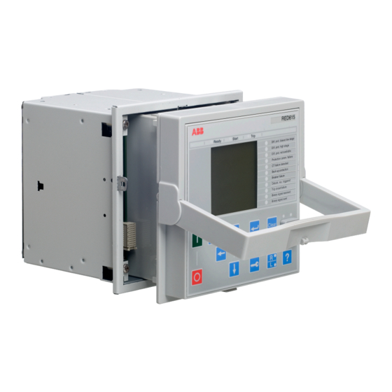
Section 3 1MRS756499 A RED615 overview LHMI GUID-F69BFFA3-FEBF-4651-954F-9669770928A1 V2 EN Figure 1: LHMI The LHMI of the IED contains the following elements: • Display • Buttons • LED indicators • Communication port The LHMI is used for setting, monitoring and controlling. - Page 27 Section 3 1MRS756499 A RED615 overview Character size Rows in view Characters on row Small, mono-spaced (6x12 5 rows pixels) 10 rows with large screen Large, variable width (13x14 4 rows min 8 pixels) 8 rows with large screen The display view is divided into four basic areas:...
-
Page 28: Leds
Section 3 1MRS756499 A RED615 overview 3.5.2 LEDs The LHMI includes three protection indicators above the display: Ready, Start and Trip. There are also 11 matrix programmable alarm LEDs on front of the LHMI. The LEDs can be configured with PCM600 and the operation mode can be selected with the LHMI. - Page 29 Section 3 1MRS756499 A RED615 overview 16 Communication LED Object control If the control position of the IED is set to local with the R/L button, the IED can be controlled using the object control buttons. As a default, breaker 1 is always the first to be controlled. If other controllable objects are available, the user can select them in the control menu.
-
Page 30: Lhmi Functionality
Section 3 1MRS756499 A RED615 overview Commands Table 7: Command push buttons Name Description • Moving directly to the Main Menu, if currently in default view or in any menu. Menu • Moving to the default view, if currently in Main Menu. -
Page 31: Parameter Management
Section 3 1MRS756499 A RED615 overview Table 10: Trip LED LED state Description Normal operation. A protection function has tripped and an indication message is displayed. • The trip indication is latching and must be reset via communication or by pressing •... -
Page 32: Whmi
Section 3 1MRS756499 A RED615 overview • The green uplink LED on the left is lit when the cable is successfully connected to the port. • The yellow communication LED on the right blinks when the IED communicates with the connected device. -
Page 33: Command Buttons
Section 3 1MRS756499 A RED615 overview GUID-E6D25BB7-850E-4AD0-9C83-4A8D3CD0B1F4 V3 EN Figure 5: Example view of the WHMI The WHMI can be accessed: • Locally by connecting your laptop to the IED via the front communication port. • Remotely through the Internet or over LAN/WAN. -
Page 34: Authorization
Section 3 1MRS756499 A RED615 overview Name Description Rejecting changes. Showing context sensitive help messages. Clearing events. Saving values to CSV file format. Freezing the values so that updates are not displayed. Authorization The user categories have been predefined for the LHMI and the WHMI, each with different rights and default passwords. -
Page 35: Communication
Section 3 1MRS756499 A RED615 overview Communication The IED supports two different communication protocols: IEC 61850 and ® Modbus . Operational information and controls are available through these ® protocols. IEC 61850 communication can be used parallel with Modbus ®... -
Page 36: Connectivity Packages
RED615 Connectivity Package Ver. 1.0 • Parameter Setting Tool • Disturbance Handling Tool • Signal Monitoring Tool • Signal Matrix Tool • Communication Management Tool • Differential Characteristics Tool Download connectivity packages from the ABB web site http:// www.abb.com/substationautomation RED615 Operation Manual... -
Page 37: Section 4 Using Hmi Locally Or Via Web Interface
Logging in Press any key except for to activate the login procedure. Press to select the user level. A070888 V3 EN Figure 6: Selecting access level Confirm the selection with Enter the prompted password digit by digit. RED615 Operation Manual... -
Page 38: Logging Out
To cancel logout, press 4.1.3 Turning display backlight on The display backlight is normally off. It turns on during the display test at power up. • To turn on the backlight manually, press any LHMI push button. RED615 Operation Manual... -
Page 39: Selecting Local Or Remote Use
The IED information is shown on the display for a few seconds when the device starts up. The same information is also found in the IED menu. Select Main Menu/Information. Select a submenu with RED615 Operation Manual... -
Page 40: Adjusting Display Contrast
The selected contrast value is stored in the non-volatile memory if you are logged in and authorized to control the IED. After an auxiliary power failure, the contrast is restored. 4.1.7 Changing LHMI language Select Main Menu/Language and press Change the language with Press to confirm the selection. Commit the changes. RED615 Operation Manual... -
Page 41: Changing Display Symbols
To move upwards in the menu tree, press • To enter setting mode, press • To leave setting mode without saving, press 4.1.9.1 Menu structure The Main Menu contains main groups which are divided further into more detailed submenus. RED615 Operation Manual... -
Page 42: Scrolling The Lcd View
4.1.9.3 Changing the default view The default view of the display is the Measurements unless set otherwise. Select Main Menu/Configuration/HMI/Default view and press Change the default view with Press to confirm the selection. RED615 Operation Manual... -
Page 43: Browsing Setting Values
When the symbol in front of the value is ↑, you can only increase the active value. • When the symbol is ↓ you can only decrease the active value. • When the symbol in front of the value is ↕, you can either increase or decrease the active value. RED615 Operation Manual... -
Page 44: Editing String Values
The symbol in front of the value is ↕, when the previous value is shown. A070757 V3 EN Figure 17: Restoring the previous value 4.1.11.2 Editing string values Activate the setting mode and select a setting. RED615 Operation Manual... -
Page 45: Editing Enumerated Values
Main Menu. To save the changes in non-volatile memory, select Yes and press A070891 V3 EN Figure 18: Confirming settings • To exit without saving changes, select No and press RED615 Operation Manual... -
Page 46: Clearing And Acknowledging
The item is now cleared and the value changes back to False. Repeat steps 2 and 3 to clear other items. 4.1.14 Using LHMI help The context sensitive LHMI help is used to get information from, for example, the selected view, menu or a single parameter. Press RED615 Operation Manual... -
Page 47: Using Whmi
The user is logged out after session timeout. The timeout can be set in Main Menu/ Configuration/HMI/Web HMI timeout. The red session timeout bar appears one minute before the timeout expires. You can prevent automatic logout by clicking Close this dialog. RED615 Operation Manual... - Page 48 Section 4 1MRS756499 A Using HMI locally or via web interface GUID-D0ACBF32-78F1-458C-853A-DAAA6E80E006 V2 EN Figure 21: Session timeout RED615 Operation Manual...
-
Page 49: Identifying The Device
• To log out manually, click Logout on the menu bar. GUID-87496248-4921-4189-A590-E8A60AF0FEB0 V2 EN Figure 22: WHMI logout 4.2.3 Identifying the device The IED information includes detailed information about the device, such as revision and serial number. RED615 Operation Manual... -
Page 50: Navigating In The Menu
WHMI settings include, for example, the client-specific setting for the WHMI language. Different users can use different languages when connecting to the same IED. The WHMI language selection is independent of the language selection for the LHMI. • Logout ends the session. RED615 Operation Manual... -
Page 51: Menu Structure
The Main Menu contains main groups which are divided further into more detailed submenus. • Language • Monitoring • Settings • Configuration • Tests • Information • Clear • Disturbance records • Events • Measurements 4.2.5 Showing all parameters Click Parameter list in the menu bar. RED615 Operation Manual... - Page 52 Section 4 1MRS756499 A Using HMI locally or via web interface GUID-F2DA9249-778C-416F-BCFF-767F1E979D27 V3 EN Figure 25: Show all parameters Click Print to print out all parameters on paper. RED615 Operation Manual...
-
Page 53: Editing Values
Click the menu in the WHMI tree. Click the submenu to see function blocks. Click a function block to see the setting values. Click Enable Write. Some parameters, for example the IED test mode, cannot be set via the WHMI. RED615 Operation Manual... - Page 54 Using HMI locally or via web interface GUID-C6230163-7FE4-4438-B863-B433682496D6 V3 EN Figure 27: Enable writing to edit a value The selected setting group is shown in the Setting Group drop-down box. The active setting group is indicated with an asterisk *. Edit the value. RED615 Operation Manual...
- Page 55 If the value is out of range, the row is highlighted in red and a warning dialog box appears. A070934 V3 EN Figure 29: Warning indicating that the entered value is incorrect • If writing values fails, a warning dialog box appears. RED615 Operation Manual...
-
Page 56: Committing Settings
Click Write to IED after editing parameter values to put the values into IED's database for use. RED615 Operation Manual... - Page 57 Click Reject to cancel saving settings. • If the parameter has an edit-copy, the original parameter value is restored. • If the parameter does not have an edit-copy, the edited parameter value remains visible until you reboot the IED. However, the edited RED615 Operation Manual...
-
Page 58: Clearing And Acknowledging
IED as active values and the new values are lost. 4.2.8 Clearing and acknowledging Reset, acknowledge or clear all messages and indications, including LEDs and latched outputs as well as registers and recordings, in the Clear menu. Click the Clear menu. RED615 Operation Manual... - Page 59 Using HMI locally or via web interface GUID-7662335C-3F76-4C14-B87E-5659FC579ECA V3 EN Figure 33: Selecting clear menu Click Enable write. In the New Value box, click True to select the item to be cleared. Click Write to IED. Click Reject. RED615 Operation Manual...
-
Page 60: Selecting Alarm View
Clearing indications and LEDs 4.2.9 Selecting alarm view Alarm view shows the status of alarm LEDs. These are the same LEDs that are located on the upper right side of the LHMI panel. • Click Alarms in the menu bar. RED615 Operation Manual... -
Page 61: Selecting Event View
Using HMI locally or via web interface GUID-6E6248B9-3F3B-49A4-A281-10FC62E4DC22 V3 EN Figure 35: Monitoring alarms 4.2.10 Selecting event view The event view contains a list of events produced by the application configuration. Click Events in the menu bar. RED615 Operation Manual... -
Page 62: Selecting Phasor Diagrams
The CSV file can be opened with a spreadsheet program such as OpenOffice.org Calc or Microsoft Excel. Click Clear events to clear all events from the IED. 4.2.11 Selecting phasor diagrams Click Phasor diagrams in the menu bar. RED615 Operation Manual... - Page 63 Using HMI locally or via web interface GUID-D698C171-5947-4A2D-9D12-186626156210 V3 EN Figure 37: Normal case with only high degrees of load currents Toggle the diagram visibility by selecting it from the drop-down menu. GUID-01FF8E6C-8FC4-47AE-8926-83C1B4B38D8D V3 EN Figure 38: Toggling the diagram visibility RED615 Operation Manual...
- Page 64 Visible diagrams are indicated with an asterisk *. Change the size of the diagram by changing the zoom value. GUID-BF7CF464-ACFC-4130-B823-A0996367B6AE V3 EN Figure 39: Zooming the diagram Click Freeze to stop updating the phasor diagram. No updates will appear in the diagram. RED615 Operation Manual...
-
Page 65: Using Whmi Help
The arrow extends outside the circle if the current value is too high Install an SVG plugin to view the phasor diagrams. 4.2.12 Using WHMI help The context sensitive WHMI help provides information, for example, of a single parameter. Click The help dialog box is displayed. RED615 Operation Manual... - Page 66 Section 4 1MRS756499 A Using HMI locally or via web interface GUID-FD2BEFF5-AF4C-4AFF-ADFA-C005A8B355ED V3 EN Figure 41: Clicking the help button To close the help dialog box, click OK. RED615 Operation Manual...
-
Page 67: Section 5 Ied Operation
Many disturbance origins are permanent and cannot be automatically cleared. The IED then collects disturbance data for later analysis. Only authorized and skilled personnel should analyze possible errors and decide on further action. Otherwise, stored important disturbance data can be permanently lost RED615 Operation Manual... -
Page 68: Disturbance Case Identification
IED. 5.2.3 Internal IED errors The IED monitors internal software and hardware errors. Internal error information is collected to the IED for later analysis. The main indication of an internal fault is a blinking green Ready LED. RED615 Operation Manual... -
Page 69: Disturbance Recording Triggering
Disturbance data is collected and stored for later viewing and analysis. The disturbance recorder data can be uploaded and analyzed, for example, with PCM600. For more information, see PCM600 documentation. 5.2.6 Disturbance reports PCM600 can be used for creating reports of disturbance recorder data. RED615 Operation Manual... -
Page 70: Fault Determination
After completing the editing of setting group values, the new values are activated. The user can either commit the edited values or discard them. Setting values can also be copied from one setting group to another. RED615 Operation Manual... -
Page 71: Ied Settings For Different Operating Conditions
IED settings for different operating conditions IED settings can be designed for various operation conditions by defining different setting values to different setting groups. The active setting group can be changed by the IED application or manually via the LHMI. RED615 Operation Manual... -
Page 73: Section 6 Operating Procedures
Clear view and to clear messages. A071264 V3 EN Figure 42: Indication message 6.1.1.2 Monitoring internal IED fault The blinking green LED indicates an internal IED fault. Internal IED fault messages are shown in a dialog box. RED615 Operation Manual... -
Page 74: Monitoring Condition Monitoring Data
All values show the momentary measurement value and some include also demand values calculated from set period. 6.1.2.1 Measured values Measured values can be accessed through the LHMI or WHMI. 6.1.2.2 Using LHMI for monitoring Select Main Menu/Measurements to monitor measured and calculated values. RED615 Operation Manual... -
Page 75: Recorded Data
PCM600 to monitor disturbance recorder data. All disturbance recordings are found in the C:\COMTRADE directory. Select Main Menu/Disturbance records. All the disturbance recorder information is listed. Scroll the view with The following items are listed in the view: RED615 Operation Manual... -
Page 76: Controlling And Uploading Disturbance Recorder Data
Disturbance recorder data can be controlled and read with PCM600. For more information, see PCM600 documentation. 6.1.3.4 Monitoring fault records Select Main Menu/Monitoring/Recorded data. To navigate between the fault records, press To enter or exit a submenu, press A071146 V3 EN Figure 46: Monitoring fault records RED615 Operation Manual... -
Page 77: Monitoring Events
6.1.4.1 Operating IED remotely With the PCM600 tool you can: • Read maintenance record and version log • Analyze disturbance record data • Create disturbance record • Read IED values. For more information, refer to PCM600 documentation. RED615 Operation Manual... -
Page 78: Controlling
A071174 V3 EN Figure 48: Selecting object To confirm the operation, select Yes and press A071170 V3 EN Figure 49: Opening circuit breaker • To cancel the operation, select No and press RED615 Operation Manual... -
Page 79: Resetting Ied
Press to activate the Clear view. All the items that can be cleared are shown: • Indications and LEDs • Alarm LEDs • Recorded data • Events • Disturbance records • Temperature functions • Trip lockout functions RED615 Operation Manual... -
Page 80: Changing Ied Functionality
The test mode can be activated using the LHMI. The green Ready LED will be blinking to indicate that the test mode is activated. Select Main Menu/Tests/IED test/Test mode and press A071154 V3 EN Figure 52: Entering test mode Select Test off or Test on with Press to confirm the selection. RED615 Operation Manual... -
Page 81: Connecting To Trip And Disturbance Recorder Functions
The active setting group can be changed by the IED application or manually from the menu. Select Main Menu/Settings/Setting group/Active group and press A071150 V3 EN Figure 53: Active setting group Select the setting group with Press to confirm the selection or to cancel. RED615 Operation Manual... -
Page 82: Copying A Setting Group
6.4.5.3 Selecting a setting group for editing Select Main Menu/Settings/Edit setting group. Select the setting group to be edited with Press to confirm the selection. Edit the settings. A070858 V3 EN Figure 55: Selecting a setting group RED615 Operation Manual... -
Page 83: Browsing And Editing Setting Group Values
The setting group values are indicated with #. A070899 V3 EN Figure 57: Setting group parameter To select a setting group value, press and to edit the value press A071168 V3 EN Figure 58: Selecting setting group value RED615 Operation Manual... -
Page 84: Activating Leds
Select Main Menu/Configuration/Alarm LEDs and press Select an Alarm LED with Press to confirm the selection and to change the Alarm LED mode. Press to change the value and to confirm the selection. For more information, see PCM600 documentation. RED615 Operation Manual... -
Page 85: Section 7 Troubleshooting
Inspect the IED visually • Inspect the IED visually to find the physical error causes. • If you can find some obvious physical damage, contact ABB for repair or replacement actions. Check whether the error is external or internal. •... -
Page 86: Identifying Communication Errors
Check the time synchronization. On the LHMI, this can be done by navigating from Main Menu/Monitoring/IED status/Time synchronization. In case of persistent faults originating from IED's internal faults such as component breakdown, contact ABB for repair or replacement actions. 7.1.4 Checking communication LEDs There are two LEDs on the LHMI above the RJ-45 communication port. - Page 87 Light sensor error Internal Fault Card in slot X000 is wrong type. Conf. error,X000 Internal Fault Card in slot X100 is wrong type or does not Conf. error,X100 belong to the original composition. Table continues on next page RED615 Operation Manual...
-
Page 88: Warnings
LCD. The fault indication message can be manually cleared. When a fault appears, the fault indication message is to be recorded and stated when ordering service. RED615 Operation Manual... - Page 89 ARC light input 1. Warning A continuous light has been detected on ARC2 cont. light the ARC light input 2. Warning A continuous light has been detected on ARC3 cont. light the ARC light input 3. RED615 Operation Manual...
-
Page 90: Led And Display Messages
Select Main Menu/Configuration/Authorization. Select the password to be reset with Press , change the password with and press again. Repeat steps 2 and 3 to set the rest of the passwords. RED615 Operation Manual... -
Page 91: Section 8 Commissioning
Checking installation 8.2.1 Checking the power supply Check that the auxiliary supply voltage remains within the permissible input voltage range under all operating conditions. Check that the polarity is correct. RED615 Operation Manual... -
Page 92: Checking Ct Circuits
CT primary being de-energized first, dangerous voltages may be produced. This can be lethal and damage, for example, insulation. The re-energizing of the CT primary should be inhibited as long as the CT secondary is open or unearthed. RED615 Operation Manual... -
Page 93: Checking Binary Input And Output Circuits
LHMI WHMI password User rights password VIEWER 0001 remote0001 Only allowed to view OPERATOR 0002 remote0002 Authorized to make operations ENGINEER 0003 remote0003 Allowed to change IED parameters, but no operation rights ADMINISTRATOR 0004 remote0004 Full access RED615 Operation Manual... -
Page 94: Using Pcm600
The IED has a DHCP server for the front interface. The DHCP server assigns an IP address to the computer connected to the front interface. The computer's LAN interface has to be configured to obtain the IP address automatically. RED615 Operation Manual... -
Page 95: Setting Communication Parameters
To open Network Connections, click Start, point to Settings, click Control Panel, and then double-click Network Connections. Double-click the connection that you want to configure, and then click Properties. Select the TCP/IP protocol from the list of configured components using this connection and click Properties. RED615 Operation Manual... - Page 96 Section 8 1MRS756499 A Commissioning A071162 V1 EN Figure 62: Selecting TCP/IP protocol Select Obtain an IP address automatically and Obtain DNS server address automatically. RED615 Operation Manual...
- Page 97 To open Network Connections, click Start, point to Settings, click Control Panel, and then double-click Network Connections. Double-click the connection that you want to configure, and then click Properties. Select the TCP/IP protocol from the list of configured components using this connection and click Properties. RED615 Operation Manual...
- Page 98 Figure 64: Selecting TCP/IP protocol Choose Use the following IP address. Enter an IP address and a subnet mask. Make sure that the IP address is unique, that is not used by any other IED on the network. RED615 Operation Manual...
- Page 99 Place the cursor in the IP Address row and enter the IP address. The used method depends on the time at which the IP address is available. Defining IP address in the Object Properties windows allows changing the IP address at any time. RED615 Operation Manual...
-
Page 100: Setting Ied And Communication
To define Modbus communication parameters, select Main Menu/ Configuration/Communication/Modbus. For more information, see Modbus Communication Protocol Manual and Technical Manual. 8.5.2 Setting LHMI 8.5.2.1 Changing LHMI language Select Main Menu/Language and press Change the language with Press to confirm the selection. Commit the changes. RED615 Operation Manual... -
Page 101: Adjusting Display Contrast
The IED has to be rebooted if the WHMI display symbols are changed. With the LHMI, the change takes effect immediately. 8.5.2.4 Changing the default view The default view of the display is the Measurements unless set otherwise. RED615 Operation Manual... -
Page 102: Setting System Time And Time Synchronization
Last Sunday, if the month has 31 days For example, if the DST is observed from the last Sunday in March to the last Sunday in October and the time shift occurs at 01:00 UTC, the setting parameters are: RED615 Operation Manual... -
Page 103: Setting Ied Parameters
Edit the settings. A070858 V3 EN Figure 67: Selecting a setting group Browsing and editing setting group values Select Main Menu/Settings/Settings and press Select the setting group to be viewed with and press to confirm the selection. RED615 Operation Manual... - Page 104 To select a setting group value, press and to edit the value press A071168 V3 EN Figure 70: Selecting setting group value Only values within the selected setting group can be changed. Press to change the value and to confirm the selection. RED615 Operation Manual...
- Page 105 Figure 72: Active setting group Select the setting group with Press to confirm the selection or to cancel. A071152 V3 EN Figure 73: Selecting active setting group Commit the settings. Remember to document the changes you make. RED615 Operation Manual...
-
Page 106: Ied Parametrization
8.6.1 Selecting test mode The test mode can be activated using the LHMI. The green Ready LED will be blinking to indicate that the test mode is activated. Select Main Menu/Tests/IED test/Test mode and press RED615 Operation Manual... -
Page 107: Testing Digital I/O Interface
To activate or deactivate an output signal for protection or other function: Select Main Menu/Tests/Function tests/Current protection/PHLPTOC and press Select the output signal to be activated or deactivated with and press To deactivate all output signals for the function, select Reset with and press RED615 Operation Manual... -
Page 108: Selecting Internal Fault Test
ABB Product Data Registration The ABB Product Data Registration feature traces composition changes related to the IED's SW or HW. After a composition change, an LCT indication is seen on the LHMI at the IED start- up. - Page 109 Section 8 1MRS756499 A Commissioning A071266 V3 EN Figure 76: LCT indication The number of composition changes can be seen from the Composition changes parameter in Main Menu/Monitoring/IED status. RED615 Operation Manual...
-
Page 111: Section 9 Glossary
Xerox Corporation, Inc. and defined in the IEEE 802.3 standard in which computers access the network through a CSMA/CD protocol. Function block. Firmware System software or hardware that has been written and stored in a device's memory that controls the device. RED615 Operation Manual... - Page 112 Modbus RTU protocol which uses TCP/IP and Ethernet to carry data between devices. Network control center OLE (object linking and embedding) for process control Polyamide Polybutylene terephthalate Personal Computer; Polycarbonate PCM600 Protection and Control IED Manager Power output Remote/Local RED615 Operation Manual...
- Page 113 Signal Matrix Tool SNTP Simple Network Time Protocol Signal output Shielded Twisted-Pair Scalable Vector Graphics Software TCP/IP Transmission Control Protocol / Internet Protocol Trip-circuit supervision Coordinated Universal Time Voltage transformer Wide area network WHMI Web Human-Machine Interface RED615 Operation Manual...
- Page 116 ABB Oy Distribution Automation P.O. Box 699 FI-65101 VAASA, Finland Phone +358 10 22 11 +358 10 22 41094 www.abb.com/substationautomation...
Need help?
Do you have a question about the RED615 and is the answer not in the manual?
Questions and answers