Table of Contents
Advertisement
Advertisement
Table of Contents

Subscribe to Our Youtube Channel
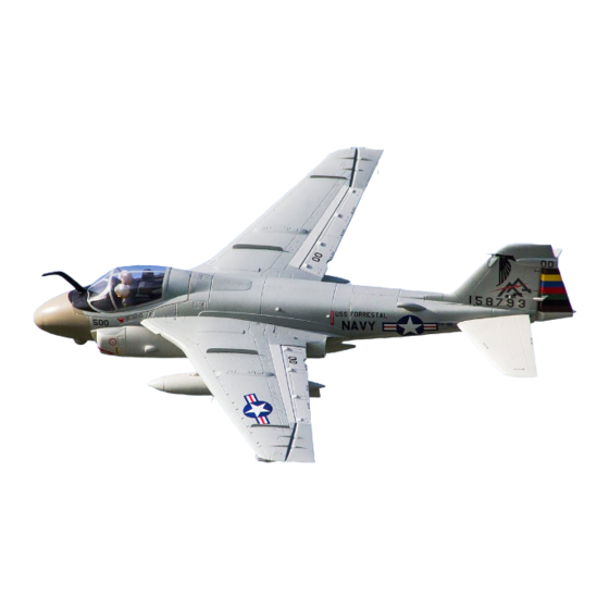
Summary of Contents for Freewing A-6E Intruder
- Page 1 EN 1 -14 15-28...
-
Page 2: Table Of Contents
2. Before beginning assembly, please read through the instructions and carefully follow them throughout the build. 3. Freewing and it's vendors will not be held responsible for any losses due to improper assembly and operation. 4. Model airplane operators must be at least 14 years of age. -
Page 3: Basic Product Information
Basic Product information • Motor 3S2S-2870KV .a:,. • BOA (SA BEG) • Servo 9g (Bpcs) • Battery 4S 14.BV 4000mAh 3SG • Ducted fans � 6-Bladed 80mm EDF • Take-off weight 19SOg (68.72 oz.) • Thrust 1900g (67 oz.) • Motor •... -
Page 4: Fuselage Assembly
Fuselage Assembly Refer to the photo on the right for proper glue points. Once the glue has set for approximately 90 seconds, join the two pieces then pull them apart, creating 'strings' of glue. Repeat 3 times then press the two pieces together for the final time, this will ensure maximum strength at the glued point. -
Page 5: Horizontal Stabilizer Installation
If you need to will replace servo, please purchase Freewing servo ,or refer to the following drawing to �67.Bmm� choose the correct size servo. -
Page 6: Main Wing Installation
If you need to replace a servo, purchase �55mm� Freewing servo ,or refer to the following (2.17 in) drawing to choose the correct size. Pushrod diameter: 0 1.2mm Drop Tanks And Bombs Installation 1. -
Page 7: Nose Gear Assembly And Installation
Nose Gear Assembly and Installation (4s and 6s Versions) The A-6 comes in two versions, the 4s standard version and a 6s upgraded version. The 4s version utilizes a basic wire type landing gear whereas the 6s upgraded version comes with a spring loaded aluminum shock absorbing style landing gear. The upgraded landing gear is also available to purchase separately if you choose to upgrade your 4s system. -
Page 8: Nose Gear Door Installation
Nose Gear Door Installation Nose cabin door list: A- Nose gear door B - Door hook1 C - Door hook2 D- Spring 1.Attach the "Nose gear door(A)" to the fuselage. 2.Use "Spring(D)" to connect the "Door hook1(B)" o the "Door hook 2 (C)". Nose Gear Steering Servo Installation Accessories list A- 9g servo... -
Page 9: Main Gear Assembly And Installation
Main Gear Assembly and Installation Main gear list (6S upgrade version) A- Electric retract B -Grub screws (M4x3mm) C -Main gear strut Full a l uminium dampin g landing g e a r 4S standard version metal landing gear D-Pin instruction (no damping) instruction E -Spring... -
Page 10: Servo Introduction
Servo Introduction 2000 µs(_ A servo or reversed servo is defined as follows: When the servo input signal changes from 1000ųs to 2000ųs, if the servo arm rotates clockwise, it's a positive servo. If it . , . . / rotates counter clockwise, it's a reversed servo. -
Page 11: Power System Installation
Power System Installation 1.Slide the "Motor(D)" into the "Ducted fan housing(C)". 2.Join the "Motor(D)" to the "Ducted fan housing(C)" using 4 "Cup head screws(B)". 3.Slide the "Rotor(E)" onto the motor shaft. ( During this process, please note the flat spot of rotor should align with the flat spot of the motor shaft ) 4.Use "Spinner(F)"... -
Page 12: Center Of Gravity
Center of Gravity The correct Center of Gravity is directly related to the success of the initial flights. Refer to the following diagram to ensure you have the proper CG. Once comfortable with the airplane, you can adjust the CG to suit your individual taste. -
Page 13: Control Surfaces Direction Setup
Control Surface Direction and Set Up After the Airplane is assembled, but before first flight, switch on the radio and ensure the throttle is in the lowest position. Engage the kill switch if one is assigned. Install a fully charged battery and connect it to the ESC. Using the radio, ensure that all control surfaces move in the correct direction. -
Page 14: Dual Rates
Dual Rates According to our test results, the following rates proved to be a good starting point. Low rates are good for initial flights or less experienced pilots. High Rates will be more sensitive to control inputs After initial flights, adjust the rates to suit your own style. -
Page 15: Troubleshooting
Troubleshooting Guide A) Li-Po battery depleted A) Recharge Li-Po battery B) Replace or recharge batteries B) Transmitter batteries depleted C) Turn on transmitter C) Transmitter not turned on Motor does not turn D) Plug in Li-Po battery D) Li-Po battery not plugged in E) Motor not armed E) Arm motor F) Replace... - Page 16 [B-ccWMg Dongguan Freewing Electronic Technology Ltd HK Freewing Model International Limited Add.:FeiYi Building,face to Labor Bureau, Fu min Middle Road, Dalang Town, Dongguan City , Guangdong Province, China Web: http://www.sz-freewing.com Email:freewing@sz-freewing.com Tel: 86-769-82669669 Fax:86-769-82033233 �� �-*�� � *%*�•�-=rf41t��&0R1 �&0 RI �j�...


Need help?
Do you have a question about the A-6E Intruder and is the answer not in the manual?
Questions and answers