Table of Contents
Advertisement
Quick Links
Advertisement
Table of Contents

Subscribe to Our Youtube Channel
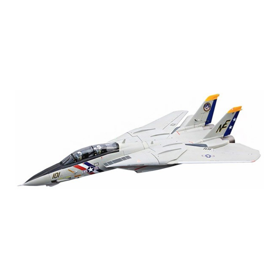
Summary of Contents for Freewing F-14 TOMCAT
- Page 1 www.sz-freew1 _____.. 15-28...
- Page 2 Before beginning assembly, please read through the instructions and carefully follow them through the build. Freewing and it's vendors will not be held responsible for any losses due to improper assembly and operation. Model airplane operators must be at least 14 years of age.
- Page 3 Product basic information Standard Version Wingload : 240g/dm (2pcs) Motor: o/r BL 3525-2050KV 8pcs) Servo: 9g / 17g MG servo (2pcs) ESC: 80A with 8A UBEC Ducted fan: 80mm 6-blade plastic fan (2pcs) Weight: 4160g (w/o Battery) Thrust: 5200g Upgrade Version Wingload : 255g/dm (2pcs) Motor: o/r BL 3530-1750KV...
- Page 4 Fuselage Assembly •Fuselage Joining the front and rear fuselage •Rudder Rudder servo Installation A-Screw (PWA1 .7•5mm 2pcs) B -Servo cover 1 .Use a servo tester or radio to center the C-Servo box servo arm. D - Rudder horn E - Rudder pushrod 2.Use glue to attach the 17g servo box (C) and F -Servo cable trough rudder horn (D) to the rudder.
- Page 5 Fuselage Installation • Elevator elevator servo installation A- Screw (PWA2x8mm 2pcs)i: B -17g servo 1. Use a servo tester or radio to center the C - Elevator servo mount servo arm. 2. Use screw (A) to secure the servo (B) to the elevator servo mount.
- Page 6 Fuselage Assembly Variable Sweep Wing Installation ',:;.,> ··::::::_ :i I , , :r.=.. , Stepo • K --- --- --- - $ · · - -¥ StepE) Stept) � ,,_ I ·<.a.· · "" <..:_} Step0 Step Cl) Carefully follow the diagrams to complete the variable sweep unit assembly.
- Page 7 Fuselage Assembly Main wing installation A--, A-Hex nut --- - D (M6mm) B-Sweep wing fixed part C-Washer (011 / 06 / 0.5mm) C1-Washer (013/08.5/0.Smm) D-Screw (HM3•Bmm) E-Screw (HM3•14mm) F-Lock nut (M3mm) G-Pushrod H-Screw (HM3•14mm) I -Bear (07•2mm) ··,'----. ---- L!). Make sure that washer C and C 1 are Note: installed correctly.
- Page 8 Main Wing Assembly Main wing Installation Step O A .. Step 6 Step@ E --- --- --- -- -U-�..1.---�- • t • 1. After adjusting the main wing, use screws to secure the main (HM3x8mm) ' A-Screw (PWA3x12mm) B- Screw wing reinforcement connecting rod to help eliminate wing C-Mainwing reinforcement connecting rod (L/R) distortion.
-
Page 9: Landing Gear Installation
Landing Gear Installation Nose Landing Gear Assembly Please assemble and disassemble the nose landing gear according to the following photo. Accessories name and specification 0 -Plastic supporting rod A - Retract controller H -0-shape connecting arm P -8 -shape connecting arm I -LED light fixed arm B -Nose gear main rod Q-U -shape plastic connecting arm V- Screw... - Page 10 Landing Gear Installation Main Gear Assembly Please refer to the following photos to assemble and disassemble the main landing gear List of parts and specs. A-Retract controller B-Grub screw (M4•4mm) C-Rear gear main rod �- D-Grub screw (M4x4mm) E-Rear gear main supporting rod F-Rear wheel axle G-Wheel (060x17mm)
-
Page 11: Battery Installation
Integrated circuit module introduction With reference to the diagram, connect the servo cables to the integrated circuit module and the receiver correctly. NOTE: Before flight, recheck every port on the integrated circuit panel to ensure none are loose. In the PNP version, the cables have been factory installed and secured using a glue designed to hold them in place to ensure integrity. - Page 12 Power System Installation Standard Version · A -Screw (PT2.3x6mm) B -Motor spinner C-Screw (HM 3x7mm) D -Metal gasket (03.1 mm) ' .£ E -80mm plastic ducted fan frame F -Outrunner brush less motor G -80mm 6-blade ducted fan H-Spinner I -Screw (HM 3x10mm) Upgrade Version A -Motor spinner...
-
Page 13: Center Of Gravity
Center of Gravity Correct center of gravity is directly related to the success of the flight, please refer to the following CG diagram to adjust your plane's center of gravity. - You can move the battery forward or backward to adjust the center of gravity. - -If you can not achieve the correct CG by moving the battery, you can also use an alternate material such as sticky back lead... -
Page 14: Control Direction Test
Control direction test After completing the assembly of the aircraft, before first flight, connect a fully charged battery to the ESC, then use your radio to check that every control surface responds properly and in the correct direction. Aileron Stick Right Stick Left •... -
Page 15: Dual Rates
Dual Rates Control sensitivity on the F-14 will change according to the wing position. It is recommended that you set up your rates using the following parameters. When changing the sweep of the wing, you will want to switch rates for ease of operation. - Page 16 Dongguan Freewing Electronic Technology Ltd HK Freewing Model International Limited Add.:FeiYi Building,face to Labor Bureau, Furn in Middle Road, Dalang Town, Dongguan City , Guangdong Province, China Web: http://www.sz-freewing.com Email:freewing@sz-freewing.com Tel: 86-769-82669669 Fax:86-769-82033233 *�*�H�-=flt:ti��R0i51 w � � �& 0 i5J tj �...


Need help?
Do you have a question about the F-14 TOMCAT and is the answer not in the manual?
Questions and answers